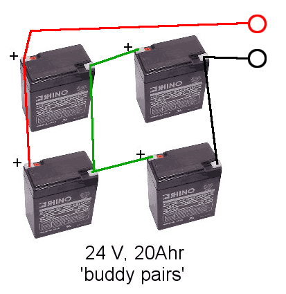
Hi.Just rewired a electric trike,4 12v Lead Acid batteries in Series and Parallel,i need to know where do i wire the charger plug in the circuit,24v charger. John
Who's online
There are currently 0 users online.
Who's new
- eric01
- Norberto
- sarim
- Edd
- OlaOst


Here is the proper way to build a 4 battery 24-volt battery pack using buddy pair wiring. The a 24-volt charger can be connected to the 2 wires coming from the battery which also go to the controller.

Chas S.
Hi Chas. Thanks for the help.Where is the best place to put the Fuses in this setup. John
I would place a fuse going into the controller, normally on the plus side, and another fuse between the charger and the batteries. Each fuse would be sized for the application it is being used for. Lets say you bike pulls 25 amps under full power. I would use about a 30-amp fuse here. If I an charging at 6 amps then I would use an 8 amp fuse. I am sure some of the others here would disagree with these sizes but I think the fuse should be a few amps greater than what I want to use. The main reason for a fuse is a catastrophic failure. At that point the current will exceed the fuse rating easily. I hate to run too close to the fuse rating because the fuse could blow when it really did not need to and then you are dead in the water.
IMO,
Chas S.
Chas,
The information here indicates to me that the buddy pair wiring method outlined above may not be optimal to maintain a balanced load on the batteries. What they say makes sense to me, but I'm pretty new at this. I think if you tapped the positive side off of the upper left battery it would fit their paradigm.
ZEV 7100 Alpine
Fort Collins, CO
astar,
It does not matter where you tap the power from on the above battery pack. To truly balance the wire resistance then you are correct. Connect the positive from the top of the batteries in the diagram. But the difference electronically is so minor your batteries will never tell the difference. Were are talking about milliohms of resistance difference. There is more resistance difference in a set of relay contacts or the contacts of an on off switch.
Grandpa Chas S.
I don't mean to contradict Chas S's nice wiring diagram, but i think he said 24v charger. In the drawing Chas has all four batteries in parallel and charging one with the charger. You don't want to charge a 12v battery with a 24v charger. With two series strings in parallel, you could tap off the positive of one of the strings, and the negative of the other. I'll do a diagram, and post it in a few minutes.
[url=/forum-topic/motorcycles-and-large-scooters/587-my-kz750-electric-motorcycle-project]KZ750 Motorcycle Conversion[/url]
[url=/forum-topic/motorcycles-and-large-scooters/588-fixing-my-chinese-scooter]900 watt scooter[/url]
Pic from http://www.electri
My guess is that the stock wiring (in blue) looks something like this. If this is the case, than I'd do the charger wiring the way it is in gray.
[url=/forum-topic/motorcycles-and-large-scooters/587-my-kz750-electric-motorcycle-project]KZ750 Motorcycle Conversion[/url]
[url=/forum-topic/motorcycles-and-large-scooters/588-fixing-my-chinese-scooter]900 watt scooter[/url]
Pic from http://www.electri
Andrew,
Great catch. The drawing was wrong, I have corrected it. Thanks for keeping me honest, we all make mistakes, bless you for speaking out. Please check the revised version and don't forget to reload your browser so it is not using the copy from your cache.
Grandpa Chas S.
Just for clarity, you are disagreeing with the information on the link, correct? They are claiming really big differences in the amp draw from the batteries during use. It seems to be more the number of connection interfaces than the wire resistance.
ZEV 7100 Alpine
Fort Collins, CO
I will not disagree with the information in the link, for their application, as they are talking about a very large battery banks used as a backup systems. I have one in my home and can run the whole house for 24 hours before the generator kicks in and charges the batteries. The generator is a 12KW unit and can run the house while charging the battery bank at 60amps. The charge takes 3 hours.
For the small amount of current we are drawing, to run a bike, the difference caused by resistance is very very small in comparison. As an example, when I use my electric stove I draw about 40 amps @ 240-volts from my backup system with 4 burners on. I have done this to see if the backup system could handle the load, no problem. The load on the 48-volt battery bank is 200 amps plus whatever else in on in the house at the time. As you can see this is a lot more power than we are using on our bikes. As I did say, there is more resistance in a switch contact than the wire and I guess I should have also said the connections have a small amount of resistance so it is a good idea to have as few connections as possible and not splice wires unless it is necessary. I also do not believe in using crimp connections or plug in connectors. The only connector needed is the main battery connector which allows you to remove the pack for charging. For all other connections I use solder covered with shrink wrap when possible or electrical tape when shrink wrap will not work.
The one item they did not talk about, or I missed it, was the buddy pairs in parallel battery configurations which is also important to help maintain good battery balance during discharge.
Grandpa Chas S.