
UPDATE: April 30, 2008 Please click here
This is a continuation of:
"Bank Charging" by charging in parallel, w/one charger.
The goal is to get the benefits of bank charging without the expense and bulk of having to use multiple chargers. This thread covers a much simpler way to do it than that covered previously. This is best done for lower-powered systems, because a large block of high-powered Anderson powerpoles would be difficult to connect/disconnect, and high-amperage fuses are more expensive. Plus, if you screw something up, your going to get a BIG spark, and possibly a fire or being burnt! Having smaller wire and smaller fuses to the charge connector is nice safety feature for a high-power system.
I had a discussion over PM with e-doggies, and he mentioned using a "jumper harness" in the charging connectors in the drawing (check above link) to wire the batteries in series. This eliminates the need for the high-power connectors in blue, provided the charge connector, and charging wiring can handle the high power when the EV is in operation.
I've seen mr_exon do this, and mf70 also mentions using a "series-parallel plug". Just to give credit where it's due; this is not my idea! I just wanted to help spread it, and incorporate some of my thoughts to help you all.
Here's the basic idea:
I'd upsize the wire from stock slightly. Here's what I would recommend:
Small scooter/ebike: 10 AWG, Anderson PP45 connectors
Large scooter: 8-6 AWG, Anderson PP75 connectors
I recommend using Anderson Powerpole connectors, because they are modular and each contact is completely isolated from the others with plastic. They can only connect when oriented 180 degrees opposite, so once the mating connector is constructed, it will only go in the right way. This makes it easy to use jumpers (see below) to reconfigure the pack on the fly as the connectors are universal. I got mine here: http://www.powerwerx.com .
It would be very helpful to label which connectors are to which batteries. And also label which connectors are to the main positive and negative of the pack. This is why I set them up so the positive and negative for each battery are adjacent to each other. This'll make it easy to measure each battery's voltage, or load test each battery.
Here are some advantages:
● All of those listed here(check bottom of post).
● Safer because just one connector can re-wire the batteries. Because the "ride" connector must be removed to insert the "charge" connector, than there's no risk of wiring the batteries in parallel and series at the same time, if the connectors are setup properly. This does not mean you can eliminate having one fuse per battery! All of them are necessary to protect each circuit from shorts!
● Easy and quick to rewire the batteries for charging or riding.
● Possible to load test each battery from the connector. This'll make it easy to find a bad battery. NOTE: be sure not to exceed the current that the fuses are rated for when doing this.
○ A convenient way to do a load test if your controller has no low-voltage cutout, is to remove the ride connector, and jumper one battery's positive and negative to the main positive and negative respectively. This will power the scooter from just that one battery.
○ If the charger is a smart type that can diagnose battery problems, than you can connect it to each individually battery and watch how the battery accepts charge, and for any codes.
● If you decide to increase the system voltage, than you won't need to buy another charger, just some more anderson powerpoles which can be added to the existing connectors.
● Easy to connect a range-extender battery pack.
● Easy to "break in" the batteries, as you can just connect the charge connector to power a 12v-120v inverter powering a lightbulb and clock. This way there won't be any risk of over-discharging the batteries because inverters usually have a low-voltage cutout, and when it does cutout you'll see by reading the clock.
● Easy to run with the batteries in parallel for a low-speed mode by just inserting the charging connector (or 1/2 voltage (see below)). This will also reduce the potential to damage the batteries when riding on low charge. This will probably not work if your controller has a low-voltage cutout. Beware: you can still damage the batteries by going below 10v/battery.
○ This can be done with a controller that has a low-voltage cutout, if you have a controller bypass contactor.
● Can bypass a battery on the road to get home if one battery dies. You can keep some "jumpers" to do this. The jumper would consist of a wire with two powerpoles on each end. You'll need N-1 jumpers as batteries, so that you can wire the other ones in the circuit as well. This will prevent the need to break up the run connector which wouldn't be so easy if it is nicely assembled with short and direct interconnects.
● In an "oh ****" situation when a controller fails closed (directly connecting the batteries to the motor) the connector can function as a disconnect if it is accessible when riding. Note: Only recommended for small scooters, as the larger powerpoles may be difficult to remove in a panic.
● Can charge from a range of DC-DC converters that have a 13.8v to 15v output. This makes it possible to charge more efficiently from batteries which store solar/wind energy, or from a larger ev which has a DC-DC converter.
● A 48v pack can have a connector wired to have two 2-battery strings in parallel for half voltage. A 72v system could have three 2-battery strings in parallel for 1/3 voltage, or two 3-battery strings in parallel for 1/2 voltage.
● If you've got an ebike with a bursh PM DC motor than you can insert the charge connector (or a 1/2 voltage connector (see last bullet), and install a contactor to bypass the controller to get regen! Best done if you've got a really steep hill to go down, and you've already used some charge from the batteries.
● If it turns out wiring the batteries in parallel to charge doesn't work for any reason, than you can easily traditionally bank charge with N number of chargers for N batteries.
● You can keep a small low-voltage emergency pack of NiMH, NiCads, or LiFePo4 to charge your scooter in an "oh ****, I'm out of charge" situation.
That's all I can think of for now; my brain needs a recharge.
PS: If your wondering why I spent so much time explaining this setup, it's because I clearly have no life. I also want to use this for myself and it helps me understand it.
PPS: I have no doubt parallel/series switching beats bank charging and that's why I'm doing it for my motorcycle and scooter.


Here's the discussion with e-doggies:
[url=/forum-topic/motorcycles-and-large-scooters/587-my-kz750-electric-motorcycle-project]KZ750 Motorcycle Conversion[/url]
[url=/forum-topic/motorcycles-and-large-scooters/588-fixing-my-chinese-scooter]900 watt scooter[/url]
Pic from http://www.electri
Welcome to the club...
Okay, this is brilliant. Totally brilliant.
One question with this is.. the maximum rated powerpole housing is for 180 amps: http://www.powerwerx.com/product.asp?ProdID=35823&CtgID=1020
My motorcycle has bursts of 300 amps draw, and I'm sure yours does as well. Clearly there are two solutions I suppose.. use multiple powerpoles in parallel to have higher capacity... or just trust that the short burst of 300 amps will be okay even though it's beyond the rating of the connector. FWIW you won't be connecting and disconnecting the circuit while it's running power.
I think a similar method could be used with their 350 amp housing, the SB 350. But it won't be as flexible.
- David Herron, The Long Tail Pipe, davidherron.com, 7gen.com, What is Reiki
I hope the PP180s can handle it. I'm planning to send upwards of 600 amps through them. We'll see.
Or not. Maybe Todd's idea of using diodes will work, I'll see tomorrow.
[url=/forum-topic/motorcycles-and-large-scooters/587-my-kz750-electric-motorcycle-project]KZ750 Motorcycle Conversion[/url]
[url=/forum-topic/motorcycles-and-large-scooters/588-fixing-my-chinese-scooter]900 watt scooter[/url]
Pic from http://www.electri
David,
I realized I could setup one PP180 Powerpole and test it today.
I tested it at 600 amps for 10 seconds. To do this, I had to wire two batteries in series. The load tester jaws were smoking, and the load-tester 4 AWG wire got warm to hot.
I felt the contact surface of the PP180 right after the test. It was barley warm. The 2 AWG wire I had in the circuit was warm to the touch.
I guess it's important to note that these are rated for power transmission. And, the specs Anderson gives for pulse current are very conservative. The pulse current graph says I can pulse 600 amps for 3-4 sec through the PP180. I can probably pulse 600 amps for over 30 seconds with marginal heating.
2 AWG wire is only rated for 94 amps power transmission, and 4 AWG is 60 amps.
[url=/forum-topic/motorcycles-and-large-scooters/587-my-kz750-electric-motorcycle-project]KZ750 Motorcycle Conversion[/url]
[url=/forum-topic/motorcycles-and-large-scooters/588-fixing-my-chinese-scooter]900 watt scooter[/url]
Pic from http://www.electri
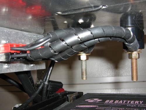
I finished the more complicated setup of doing this on my bike. Here's the setup:
"Bank Charging" by charging in parallel, w/one charger
Comments here: Re: Re-amped the beast
In general, I would not do this for a high powered system. Anything requiring larger than PP45s (and 10 AWG wire) I would shy away from due to the time required for setup, hassle dealing with the connectors, and expense of the components. This makes it a fair option for small scooters, ebikes, and pocket bikes. Also, it can be done with multi-pole and multi-throw switches which might be an easier to manage system when done.
For example, a 24v system appears to only need one DPDT (double pole double throw) switch. It looks like it would take N-2 poles as the number of battery terminals, and half of those double throw.
[url=/forum-topic/motorcycles-and-large-scooters/587-my-kz750-electric-motorcycle-project]KZ750 Motorcycle Conversion[/url]
[url=/forum-topic/motorcycles-and-large-scooters/588-fixing-my-chinese-scooter]900 watt scooter[/url]
Pic from http://www.electri
I have (4) 12V 20Ah AGM's wired with individual leads from each terminal to a block of PowerPoles. On the charger-side of that connection, all negatives go to one stand-off and all the positives to another. Then I can just clamp the stock 12V charger to the stand-offs.
My question is this:
Once the entire pack has been parallel charged with the 12V charger, which is the best wiring configuration in which to let it rest:
1. Disconnect the charger clamps from the stand-offs and let the pack rest in parallel as 12V 80Ah?
2. Disconnect the charger "plug" from the scooter, and allow each 12V 20Ah battery to rest on it's own?
3. Disconnect the "charger" plug and reconnect the "ride" plug and leave the pack in series as 48V 20Ah?
4. It really doesn't matter at all?
Thanks,
Harlow
Harlow, funny that you mention it, I'm doing the same thing to charge using terminal standoffs:
I usually just leave mine in parallel until I'm ready to ride. I don't think it matters much though, as charging them in parallel should have charged all of the batteries to 100% SOC, and that is the goal of doing this. It shouldn't hurt to leave them in parallel until you are ready to ride.
The main risk is if one battery has a shorted cell, then it will pull the other batteries down in voltage. It is probably best to not leave them paralleled if the scooter will sit for an extended period of time.
[url=/forum-topic/motorcycles-and-large-scooters/587-my-kz750-electric-motorcycle-project]KZ750 Motorcycle Conversion[/url]
[url=/forum-topic/motorcycles-and-large-scooters/588-fixing-my-chinese-scooter]900 watt scooter[/url]
Pic from http://www.electri
It's not too "funny". I got the idea from you in one of your e-Mails. You have a very neat set-up on your bike. I didn't want to find a place for on-board stand-offs, so mine stay with the charger in the garage. My little scooters never leave the neighborhood. If I traveled, I would want the stand-offs to stay with the bike so I could charge from anyone's standard 12V charger.
Thanks for the advice. The easiest for me will be to completely disconnect the charger plug from the PowerPoles and let the batteries sit as individual 12V 20Ah, until it's time to ride, and then plug in the series jumper. I can see the plugging in and out alot can be tedious. Switches would be a lot easier, but not as failsafe as changing connectors.
Harlow
thanks man
I just Re-laced my first spoked wheel! and it was trued by spinning it in my hand