Folks,
I have purchased a replacement hub motor and controller from GreenEMotor. The hub motor is a 1500 watt brushless and is shown in the photo below, along with a closeup of the label on the controller.
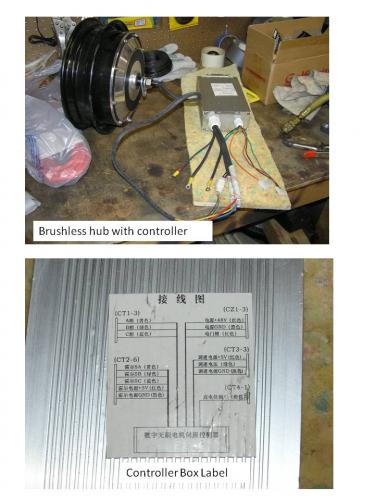
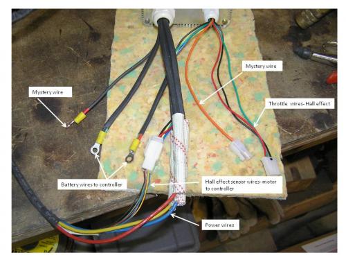
According to Allen of GreenEMotor, the diagram was included with motor. Unfortunately, I do not read Chinese. I have attached an image of the controller and wires. Some of the wires I can figure out, but I am not sure of the function of 2 of the wires. I suspect one wire, possibly the orange wire is the power wire from the switch. The other wire is truly a mystery. Has anybody seen this arrangement or is able to determine from the label what the functions may be of the 2 mystery wires?
All help is appreciated!
Thanks!
Les


At 1500w one should be for shutoff.(brake).Any attempts to juice it up and try reading from the two Mystery wires? Polarity and voltage may give some ideas.Ps. Leaving throttle unplugged...
The orange wire should be the brake wire. One of the reds will go to the switch, just make sure you get the right one to the pack and the right one to the switch. By the way, how much did this kit set you back?
-Warren
Keep the rubber side down and the shiny side up.
The kit was $499 plus $68 shipping. Supposedly, it will hit 34 mph on 48v. Allen of GreenEMotor says they have run the motor on 60v and encountered no problems.
It was a toss-up between Xtreme and GreenEMotor. Xtreme appears to be a good company and sells a quality product. Unfortunately, they use a disc brake on their motor, which would have required a more extensive mechanical fit-up on my scooter. The GreenEMotor motor has a drum brake.
The first order of business will be getting the hub motor fitted to the swingarm. The axle's flats are slightly larger than the old motor. Along with the swingarm fit-up will be the attachment of the keepers, the pieces that keep the axle from rotating.
Anyone know why the controllers are located relatively close to the motor on the brushless hub motors? The original controller is located at the front of the scooter. I will need to fabricate a mount at the back of the scooter if the controller is kept there.
I believe the pack wires are not to hard to identify. They are heavier and have ring ends. Either the orange wire or the shrink-wrapped red wire is the switch wire. Hooking up the brake wire may be a problem. That appears to buried in the harness somewhere since that function is handled by interrupting the switch wire to the controller.
Thanks!
Les
I am in the process of installing the motor. The axle flats are about 14mm. The original slots on the swingarm are about 12mm. Between an angle grinder and a file, the slots were widened and the motor fit onto the swingarm. The axle keepers were installed, requiring drilling and tapping new bolt holes in the swingarm. This was not big deal except the I was working next to the floor, not a particularly good angle to turn the tap. I broke the tap and after implementing plan C, or was it D, the broken piece was removed. A new tap was purchased and the tapping completed. The drum brake was strictly a boltup affair, not requiring any modifications (yet). While tightening the axle nuts, an interference between the motor body and a shock bolt developed. I need to work out why there is an interference. The fix may be as simple as reversing the shock's bolt.
The controller was disassembled to determine if up-volting the motor/controller would be practical. The capacitors are 63v pieces, which means that a conversion to 60v will not be happening with this controller. There are whole raft of power transitors in the controller. Someone must be reading VisforVoltage because the capacitors were hot-melt glued to the circuit board. I will post pictures of the controller eventually.
I have a bit of mechanical work to complete. The step after that will be to juryrig the controller and attempt to spin the motor. Assuming the test goes well, I will need to install the controller. There does not appear to be a good location at the back of the scooter. The original controller was installed in the front.
Any ideas if the motor controller wires to the hall sensors are sensitive to wire length?
Les