Hello
I've increased the voltage on my scooter from 48V to 60V/72V (switchable), however the regen doesn't work at the higher voltage (for some odd reason, it does work going backwards at 60V/72V?....just rolling backwards, there is no reverse gear). When I switch back down to 48V, it works fine (forwards and backwards). The controller is a JH BLDC motor controller....I think it's from Taiwan. It has 3 poles, with 5 4107 MOSFETS per pole (3 for driving, 2 for regen, 15 total). The controller gets a bit sketchy at 72V (as the FETS are underated at that voltage, so I only use it on the flats for short periods on crazy speed...70km/hr last speed check. The main surge caps are rated at 63V and I plan on upgrading a controller to 100V caps and adding some water cooling in the future.

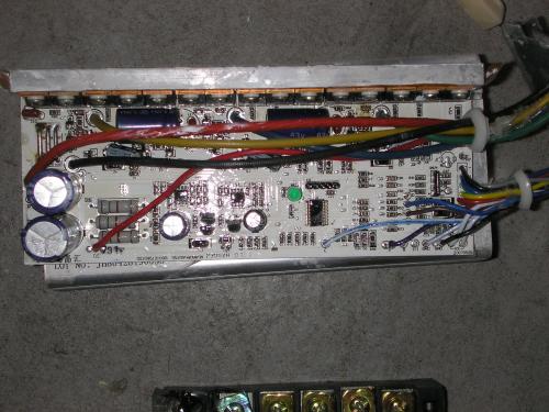
Anywaym back to the regen problem, my guess is that the 3 50V caps used to open the regen MOSFET gates are under powered? On the picture above, they are the small caps seen just under the black and blue wires, just below the big 63V caps. (BTW, I'm just completely guessing at this one by staring at the circuit board). Just beside the shunt bars, there seems to be a couple triacs (one for each MOSFET, series repeated 3 times) and a bunch of passive stuff.
Here is a picture of the bottom of the controller.

So does anyone know how to modify this circuit and/or what would be the likely problem? Any explanations to go along? As mentioned, my totally unscientific guess is an undersized 50V cap to open the gate but if so, why does this occur?
Thank you
Andrew


Could the issue be that there is some protection against over-charging an already full battery (by applying regen immediately after a full charge)?
This protection would have been set at or below the original, lower battery voltage.
It might interpret your over-volted battery as super-charged in the current setup and therefore disable regen.
Mr. Mik
This information may be used entirely at your own risk.
There is always a way if there is no other way!
No, I don't think that is the problem, since REGEN works fine on a fully charged 48V pack.
From following the traces, here's the list of actions to cause regen
1. Apply the brakes, lines from sensors on the brakes go to the controller (2 lines, 1 for each brake level)
2. These lines go through some resistors and caps (basic filter I guess), then into the micro.
3. There is 3 lines from the micro to the passive element cluster, with the gate-opening caps (the 50V ones mentioned before). BTW, these caps are charged from each of the phase lines......cue uh-huh moment!
OK, I'm pretty sure this is the problem. Since the caps were origionally 50V, they wouldn't dump to the phase lines when open since would always be at a higher potential and would go to opening the MOSFET regen gates. Since they are now smaller than the driving voltage, when they are triggered by the brakes, they just dump to the drive phase lines.
I'll try switching them to something bigger and report if it works or not.
Another thing that is interesting with this setup is that the regen (with sufficiently large caps)would always win over the drive lines, meaning it's impossible to put power to the motor and brake at the same time.
One problem is at 48V, the regen is quite harsh, so it would be cool if the micro could somehow modulate the regen action. I'm hoping the 72V regen (if it works) doesn't cause a superman-over-the-bars action.
Anyone have ideas on modulating regen with this setup? There is a 5 pin header right beside the micro so reprogramming could be possible. However, I have no idea what the chipset it and it's covered with some secret sauce to prevent seeing the model number.
Any thoughts/advice would be appreciated.
Thanks
Andrew