
Hi everyone, am running into some issues with wiring up a BMS kit into my 48V lifepo4 setup. I have emailed 'Cyclone motors' several times but get the same diagram sent to me which looks hand drawn and makes no sense to me. If anyone can please help, that would be great.
and the diagram sent to me is this:
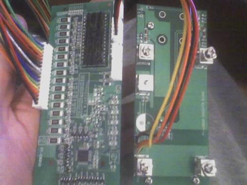
The 2 bottom terminal posts have B- and B+ on them, and the 3 top terminal posts have P+, PCH-, PDCH-
On the dodgy schematic it has most of the termianls 'crossed out' with an X???
The bike has been running well for some time but I really would prefer to charge and discharge with this BMS if I can. It was the actual one sent with the batteries and charger about a year ago.
THANKS GUYS.
Jon

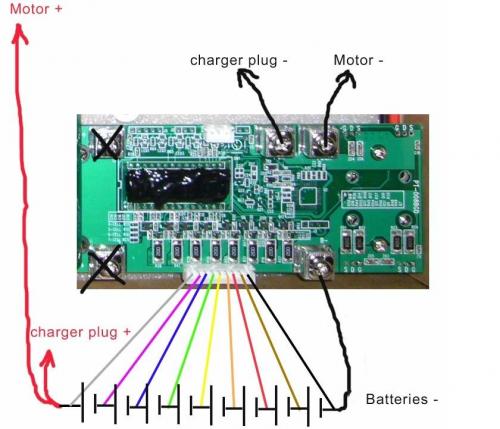
Charger plug positive is the same wire as the wire to the controller. So you can wire both those positves to the same positive terminal on the pack. The function of the bms is different for charging and for discharging, so the negatives need different terminals on the bms for each plug, one to the charger and one to the controller. All the other little wires go to each cell group in the battery, to monitor the level of the individual cell groups to balance the pack. I'm not sure which end of the cell group these wires attach to, positve side or negative.
Be the pack leader.
36 volt sla schwinn beach cruiser
36 volt lifepo4 mongoose mtb
24 volt sla + nicad EV Global
Ok thanks dogman..makes a bit more sense now. I have now wired it up except the little wires, I will wait and hopefully someone may know whether the little wires go to pos or neg on the battery pack. I don't want to risk damage. Should I bother with the BMS. Is it worth all the wiring hassles and will I get much more distance and life out of batts??
"No officer...it's only 200 watt"
:) first to answer your question with a question ! which is werth more to you , increased batt. life , or the time spent installing the bms ??? as to haw to hook it up ! it lookes like wires read from right to left black to the - neg. pole of the bat. then brown to the + of that cell and-neg. of the second cell then continue to the next juntion with red than ornge yellow and so forth! The sequence is international code !! you should have a total of 17 wires for 16 cells have fun later
thank GOD I wake up above ground !!!!
Ok so the black goes on -neg of 1st battery and 2nd wire (brown)on the pos of that same battery. THen the 3rd wire are you saying goes to -neg of the 2nd cell?? so 4th wire is pos of the 3rd cell...and so on. Is this right?? or is the 3rd wire starting on +pos of the 2nd cell and 4th wire on -neg or 3rd cell?
Thanks strawhistle, I'm getting there.
:?
"No officer...it's only 200 watt"
Since the pos terminal of each cell in the pack is connected to the neg terminal of the next cell there is no point in connecting 2 colored wires to the pos of the 2nd and the neg of the 3rd (and so on) because they are the same potential.
Start with the neg terminal that has the fat black wire connected to it, and connect the black wire to it. Then start connecting the colored wires only to the neg terminals, but don't mix up the order. The last colored wire (grey) goes to the pos terminal of the pack (last cell).
Cheers bud,
I have done what you suggested. I have 16 cells in my pack and the diagram only has the 8. I had 17 wires all up. I have conncted all to the neg. in order except the 17th wire which is on the pos. Hope its all correct. I put him on charge just b4 and it seems to be ok. Sitting in float/maintian mode.
I am thinking of using this BMS only when charging as my controller has under and over cutoff and is programmable. Do you think this is ok to do??
Thanks again.
"No officer...it's only 200 watt"
It should be OK. But there's no harm in keeping it connected at all times.
Does your BMS include LVC function? Your controller monitors the voltage of the entire pack, whereas a LVC monitors the voltage of each one of the cells.
One of the cells voltage may go under it's defined minimum, but the voltage of the pack will still be above your controllers cutoff, and therefore the cutoff function may not engage, thus damaging the bad cell.
I'm not really sure if it does have LVC. Is there an easy way to tell?
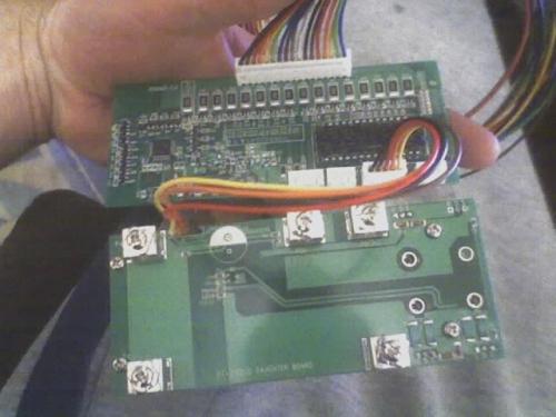
Also do you have any ideas as to making a housing for these two small chipboards? I believe they get a bit warm whilst running from what I have heard. I got this BMS with the battery pack a while ago and I think technology for BMS has moved on a little since. Are there many BMS systems that you know of? THanks
"No officer...it's only 200 watt"
If the BMS doesn't have FETs (Field Effect Transistors) on the board then it probably doesn't have LVC.
http://www.bcae1.com/tranfet.htm
righto,i'm reasonably sure it doesnt have that, I'm not really sure, I'm just a poor fitter/turner.its all 'trial and error' with me :?
I will make a harness and use this bms just for charging, I charge every day so it shouldnt be too much of a problem if I balance the cells out every night I guess. I have seen some really nice 'do-it-yourself' BMS units out on endless sphere but the prices are pretty steep and they are bloody huge. I am on the hunt for a reasonably sized one that will go on my bike but not a 'ping' type BMS as they have a very small limit for the draw I am using and will prob melt or at least continually shut off up hills.
Thanks Dave.
"No officer...it's only 200 watt"