YAVLiC - BMS blues
Last week the kit including the BMS arrived. No circuit or wiring diagrams, just a pile of parts. Hmmm...
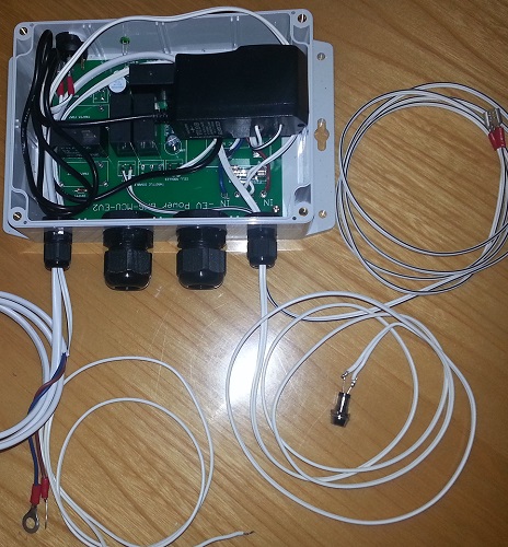
The BMS consists of a module for each battery cell and a "control unit" if you can call it that.
The BMS components are from EV-Power. Here is a link: EV Power cell module.
The "control unit" seems to consist of a few relays and a butchered plugpack which floats around in the box. It seems that I am supposed to connect the mains to the Vectrix charger through this box. As far as I can determine without tracing the tracks on the PCB, it is supposed to switch off the mains when the battery is charged.
BMS Module Testing
Since I am not going to entrust a $4000 battery to a pile of components which I don't understand, I started by testing the BMS modules. I hooked up the modules to a Lab power supply. A Fluke multimeter was connected via separate leads directly to the module and a second multimeter was used to indicate the state of the Solid State Relay (SSR) on the module. Like this:
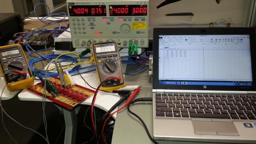
It took about 2 hours to measure all 42 modules. Here is the data:
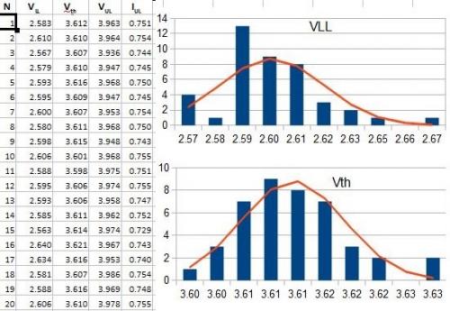
- VLL is the cell voltage lower limit (LL). Below this voltage, the SSR goes open circuit.
- Vth is the threshold at which the module starts to shunt some of the charging current through itself. I measured the voltage at which the module starts to draw more than 10mA.
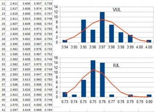
- VUL is the cell voltage upper limit (UL). Above this voltage, the SSR goes open circuit as well.
- IUL is the shunt current drawn by the module at VUL.
In retrospect, I should have also recorded the shunt current at maximum allowable battery voltage which is 3.65V for the CALB CA66Fi cells. However, the current rises rapidly from Vth and reaches around 0.5A at Vth+10mV.
The only parameter which approaches a normal distribution is Vth. For the other parameters the production process seems to be less well controlled.
A significant worry is VUL. As can be seen from the measured values, VUL is 3.965V (average). This is 0.315V higher than the maximum allowed as per the battery datasheet. This is also the voltage at which the SSR switches to open circuit (OC).
However, the real worry is that the control unit does not know when the first cell has reached it's maximum voltage and the BMS module starts shunting current. By the time the SSR switches to open circuit, at least one cell will have been cooked for a while.
The maximum shunt current achieved by the BMS modules is 0.8A, some only get to 0.73A.
I don't think that shunting 0.8A when charging with 10A or 15A is going to make much of a difference to a cell.
How it ought to work
To properly manage the battery and to be able to equalize the pack, the charging system needs to have at least 3 states:
- Nominal charging, e.g. C/4 until the first cell reaches the maximum allowable charging voltage and the BMS module starts to shunt current. The chain of SSRs must go open circuit at this time.
- Equalization phase. The battery charger reduces the charging current to a value not much higher than what the BMS modules can shunt, in this case 0.8A or maybe 1A.
- Charge complete. When the battery pack reaches VBatt = N × 3.65V, all BMS modules should be shunting current and all cells should be at SOC = 100%. The charger reduces the current to 0A.
A "real" charger should of course also have a state for the case where the initial VBatt is below the lower limit, timeouts, alarms, etc...
Conclusion
I have the wrong BMS modules. They might be designed for cells which have a Vmax=4.0V (maybe Thundersky?). They also switch at the wrong time.
The modules don't seem to be suitable for the cells I have because:
- The modules don't indicate when the first cell has reached Vmax and shunting starts.
- The SSR switches at the wrong woltage for my cells.
- By the time the module's SSR switches, at least one cell (but probably many) will have been cooked for a while with nominal charging current minus 0.8A
Grrr...
- manfred.bartz's blog
- Log in or register to post comments
Who's online
There are currently 0 users online.
Who's new
- eric01
- Norberto
- sarim
- Edd
- OlaOst
Support V is for Voltage

Comments
Re: YAVLiC - BMS blues
the max voltage on LiFePO4 cells is 4.3v - that's when part of the electrolyte starts to break down
between 3.4v and 4.3v, a separate action is occuring. the short of it is if the voltage is held above 3.4v at low current the cell is being overcharged, just in a different way to going past 4.3v
That's partly why the official Vectrix Lithium bikes have such a high failure rate - they balance by holding the fullest cell(s) at 3.6v while shunting ~1A past for hours at a time.
3.65v is the usual cv stage voltage for charging a LiFePO4 battery, which is why that number is in the datasheet, but it is not an outer limit.
The data sheet assumes you are using a cc-cv charge profile
with the vectrix charger, we are actually using a cc-cc charge profile (10A until voltage reaches 153v, then 3A until voltage reaches 153v
The job of the BMS is to do two things:
1) stop the charger from over-charging any one cell, either due to imbalance or the charger going crazy (a very real problem for the ESD chargers)
2) stop the charger from charging an over-discharged battery (over-discharging causes micro-shorts to form which causes all kinds of issues)
The above can be achieved without measuring at the cell level, its just a shame that such a product does not exist (although i know of one under development)
I have tried centralised BMS's that have a wire from each cell going to a central box.
I just couldn't find one for 42cells, or even groups of smaller ones that could disconnect the charger or not also cause other issues.
so I use a cell level BMS
The cells themselves do not become unbalanced unless they are overcharged or have been over-discharged (due to mirco-shorts).
Their self discharge rate is 0 and the coulomb efficiency is 100%
The tricky thing with a cell level BMS is it does introduce discharge at the cell level, and it isn't exactly even
So balancing becomes necessary, of which top balancing is the easiest
The upside to that is if you do over-discharge a cell, without killing it completely, the BMS can usually keep the battery balanced
For a substantially unbalanced battery, the BMS will disconnect the charger during the 10A stage. This is actually less stressful on the full cell(s) as when charging at 10A, 4v is a lower state of charge than 3A@4v
When that happens, it means the imbalance is too large and indicates a problem.
The BMS only has to deal with a minor imbalance, anything more (for instance after replacing a cell) and the balancing should be done manually
as a side note: LiFePO4 cells come from the factory at either 50% or 100% SOC, depending upon the manufacturer (CALB and WB is 50%)
The first charge after putting brand new batteries in will usually end with the BMS disconnecting. If the capacities are close together (CALB usually is) then the pack will top balance over the first dozen or so charge cycles.
For this application the turn off voltages and shunt voltage/current's are accurate enough
VLL just has to be above 2V. basically if a cell is below 2v at no load, you want to be paying attention at the start of the charge.
2.5v is probably a bit conservative, but that's ok.
VUL has to be below 4.2v, for obvious reasons
Vth has to be above 3.5v because you don't want to be shunting just because you are fast charging (above 1C continuous or during hard regen).
it should be close to the average charge termination voltage (in this case it's 153v/42 cells = 3.64v)
As far as wiring the BMS, that gets covered along with a host of other details in the conversion video (part 8):
http://www.youtube.com/watch?v=ocv-aiQoq3g&list=PLCFDD8780E3FBEFD5&index=8
Having said that, in the video 40Ah cells are being used so the layout of the cells is a little different, however, the BMS is the same.
Matt
Daily Ride:
2007 Vectrix, modified with 42 x Thundersky 60Ah in July 2010. Done 194'000km
Re: YAVLiC - BMS blues
For posterity a clarification received from Matt:
There is actually about 1 minute of no charge between those 2 steps during which the battery voltage falls back to well below 153V.
Re: YAVLiC - BMS blues
It really is pathetic that I had to reverse engineer the BMS controller.
Anyway, here is the circuit diagram (done with TinyCAD):