This is Mik's idea that was posted in thread Battery Break In Process.
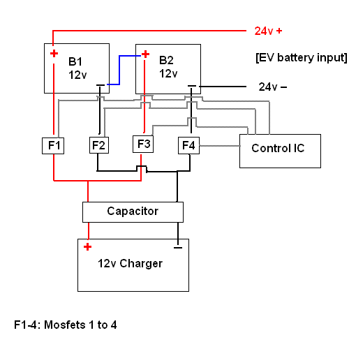
The idea is to split the output from one 12v charger into multiple isolated outputs. Maybe this can be done with mosfets, capacitor(s), and a programmable IC of some type to switch the mosfets. This would allow for "bank" charging with just one high-amp charger (such as a 40-50 amp Vector charger) reducing cost and complexity.
Here's what I'm thinking of (simplified for two batteries to demonstrate concept):

Does anyone have any ideas? Is there any device on the market now that can split one DC input into multiple isolated outputs?


Thanks for making the drawing, Andrew!
I guess the Control IC should also be connected to the individual batteries to enable monitoring of the voltage drop whilst charging the other batteries.
My understanding is that this voltage drop says a lot about the batteries condition and could be used to "plan" the voltage, current and duration of the next charge cycle for the individual batteries.
Mik
This information may be used entirely at your own risk.
There is always a way if there is no other way!
I have circled the trouble spot on this diagram. As you can see the positive wire from the charge and the negative from the charger are connected to the interconnect wire for the 2 batteries. in other words, "THEY ARE A DEAD SHORT!". If you want to share a single 12-volt charger with 2 batteries the batteries MUST BE in parallel.
Grandpa Chas S.
I do not think this would be the case, because F1 and F2 will be turned off whenever F3 and F4 are on.
This information may be used entirely at your own risk.
There is always a way if there is no other way!
Sorry I thought F1 though F4 were Fuses since F is normally the destination for a fuse. I now understand the note on the diagram as you show F1 through F4 are Mosfet switches.
If the switches are controlled correctly, the batteries will be charged by one charger with an increase in charge time.
Grandpa Chas S.
Mik has the idea. Sorry I wasn't more clear. F1 and F2 would switch on for a set duration (maybe 1 ms), than switch off BEFORE F3 and F4 are switched on.
Anyway, this is probably too complicated to be easy to implement. Another idea I was thinking of would just be to wire the batteries up in parallel for charging. To do this, the series connections between batteries would have to be disconnected as Chas S pointed out.
BTW, Chas, do you know how to take the space it added before my table out?
EDIT: ok I think I fixed the spacing problem.
Chas EDIT: Just couldn't resist. LOL
[url=/forum-topic/motorcycles-and-large-scooters/587-my-kz750-electric-motorcycle-project]KZ750 Motorcycle Conversion[/url]
[url=/forum-topic/motorcycles-and-large-scooters/588-fixing-my-chinese-scooter]900 watt scooter[/url]
Pic from http://www.electri
lol, Chas and his mad html skills. Maybe you could do a tutorial? That would be helpful.
Anyway, I've been thinking some about this. Even if I did find a cheap programmable or other IC to do the switching, the system would waste energy. The cost for two mosfets for each battery could add up, not to mention the added complexity (I'm trying to make things simple). And, I'd need to figure out what a suitable switching frequency and duration would be.
I'm thinking of a simpler approach. To just break the series connections and connect the batteries in parallel for charging. I got the idea from Chas above, and this is known to work. I'll start a new thread. Here it is: "Bank Charging" by charging in parallel, w/one charger.
[url=/forum-topic/motorcycles-and-large-scooters/587-my-kz750-electric-motorcycle-project]KZ750 Motorcycle Conversion[/url]
[url=/forum-topic/motorcycles-and-large-scooters/588-fixing-my-chinese-scooter]900 watt scooter[/url]
Pic from http://www.electri