A forum to collaboratively and openly develop repair and maintenance procedures for Vectrix Maxi scooters.
This forum / thread is not a manual yet and will possibly contain untested, speculative and potentially dangerous material and errors.
Mr. Mik

A forum to collaboratively and openly develop repair and maintenance procedures for Vectrix Maxi scooters.
This forum / thread is not a manual yet and will possibly contain untested, speculative and potentially dangerous material and errors.
Mr. Mik

There are currently 0 users online.

One of the first steps to get my Vectux going was to try to repair the side stand.
Until the battery was removed it was not obvious if the whole side stand bracket could be unscrewed and then screwed back on.
Because of this I decided to try a epoxy-resin repair job rather than welding.
The pin had fallen out when I gently wobbled the side stand by hand.
A more likely scenario would be that it falls off whilst riding or gets shot of by the spring that it holds. It might then be very hard to find....
So here are the dimensions in case you need to make a new one:
The cause of the breaking off was probably that the side stand wobbles a bit. It then puts enormous pressure onto the pin until it breaks off.
I used diamond tipped bits and a rotary tool to clean out all rust from the hole and to roughen up the pin surface to enable good bonding. Then cleaned with compressed air to remove all dust.
Using the side stand (before adding a washer and tightening it) to push the pin up a little bit enables the epoxy to set the pin in a position in which it will not be broken off again by the side stand.
Time will tell if this repair lasts once the Vectux is off the rock again and being used.
After removal of the batteries it was obvious that it would be possible to unscrew the entire stand bracket, remove it from the scooter and weld the pin back in.
The pin can turn into a nasty bullet when it gets catapulted out of the hole by the springs - wear safety goggles during repair attempts!
Adding a third washer enables tightening of the stand screw to the degree that the wobble is completely eliminated and it still moves sufficiently freely.
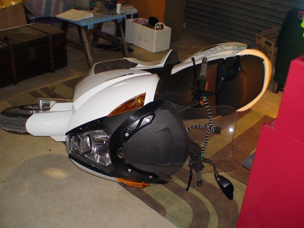
I removed the panels to get better access, and I needed to remove many of them anyways to get to the batteries etc.
The same side stand repair could probably be done without removing any panels.
I waited 72 hrs before installing the springs again to let the epoxy cure.
Once the Vectux is up and running I'll let you know if this repair lasts...
Mr. Mik
This information may be used entirely at your own risk.
There is always a way if there is no other way!
I have identified the source of the "sickly sweet" smell. (See http://visforvoltage.org/forum/3446-vectrix-not-dead-yet-smelling-funny-and-grounded for the lead-up to this)
It originated from the connecting point of one of the three cables from the motor controller to the motor.
It seems obvious to me that laying the scooter onto it's side has nothing at all to do with the failure; in my opinion you could run that controller board in an aerobatics plane in full flight if it is put together properly.
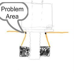
The smell comes from the heating and burning of the waterproofing clear film (??=lacquer??) applied to the whole surface of the MC, or the burning of the board itself.
I believe the half-moon shaped lighter areas at 2 and 4 o'clock around the connector C are areas where the board got hot.
At 6 o'clock is a black lump of burnt "lacquer".
Click image to enlarge.
Once something gets hot, the lacquer melts, I believe, then runs into cracks and further increases resistance. It sets when things cool down, and next time you ride your scooter the problem is worse, until it gets so hot is starts to smolder and smoke and turn black:
Click image to enlarge.
My guess is that the connector was loosened when the tech replaced the main fuse.
The screws fixing the three cables to the connectors undo in the same direction as the studs they are fixed to; undoing the screw can loosen the stud going into the board.
It would then be fastened with insufficient torque by only screwing the nut back on and is subject to loosening due to vibrations, particularly if the gearbox is faulty...
Alternatively, or rather in addition to this, lacquer could have gotten into the space where the stud is making contact with the copper of the board, increasing resistance and causing heat.
It might have gotten in when it was sprayed on and was still liquid, or in fragments when the cables were undone and the stud was loosened. It might have been fastened again with small bits of hard lacquer underneath it; this would increase resistance and lead to heating up of the connection until the fragments melt and run down the stud.
Note the lightened, half moon shaped area at 6 o'clock on connector A. I believe it was also heating up, but did not get hot enough to melt or burn the lacquer.
Click image to enlarge.
Click image to enlarge.
Click image to enlarge.
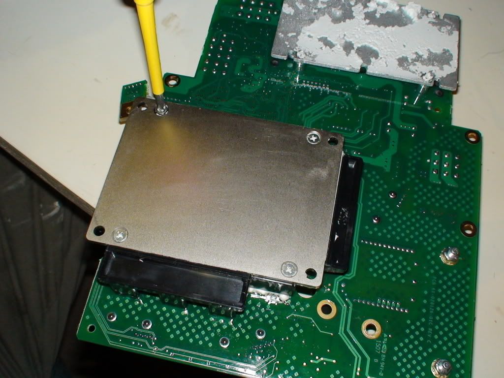
An attempt to access and assess the damage from the back of the board was unsuccessful; the metal plates appear to be glued or siliconed on.
Click image to enlarge.
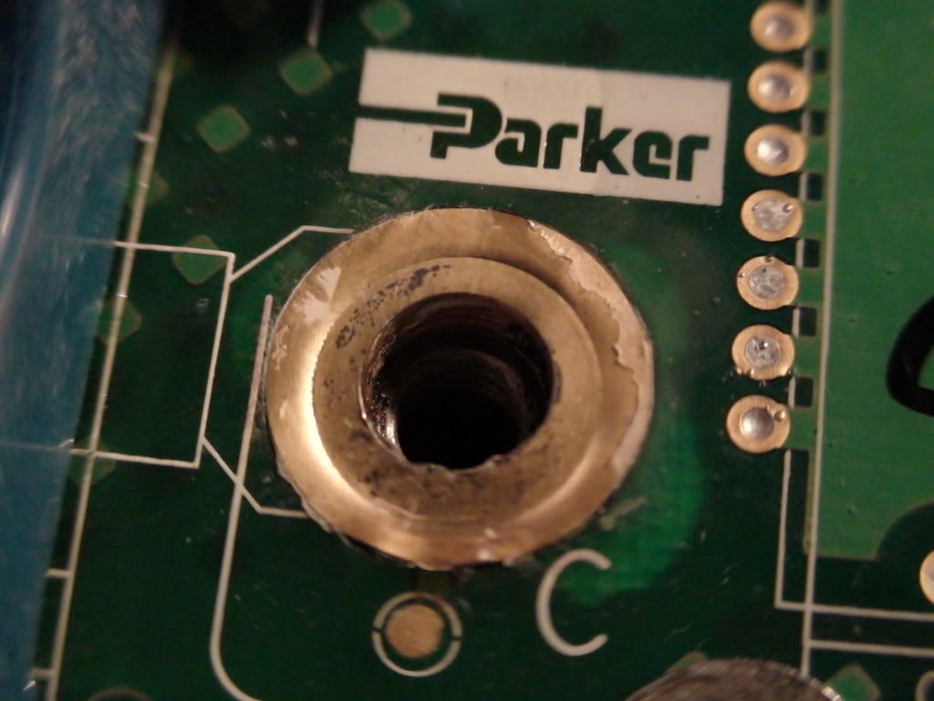
After removing the silver washer an irregular edge from 5 to 8 o'clock became apparent. I am not sure if it is cause or effect of the problem; it might be due to poor soldering, but I am not sure yet. I might try to re-solder the edge.
Click image to enlarge.
Click image to enlarge.
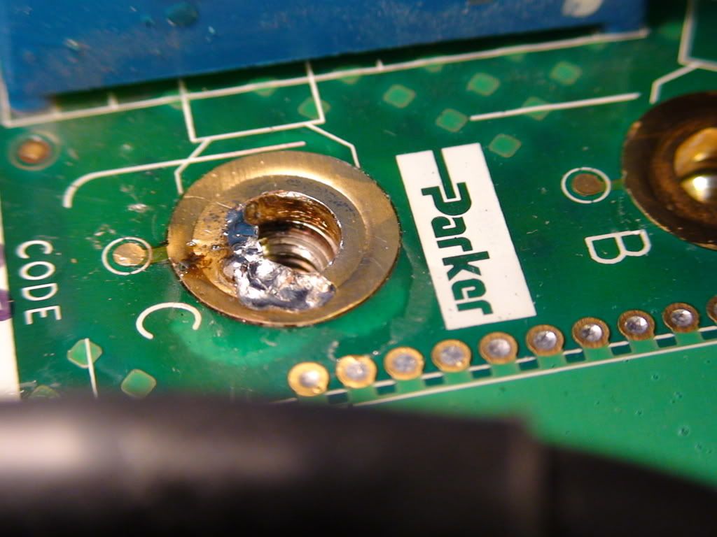
I polished things up, but have not used contact cleaner yet. I bought some today and will use that, too.
Click image to enlarge.
Click image to enlarge.
I also bought heat conducting paste and circuit boad lacquer to seal it all properly again once I am finished with it.
I intend to use about 5Nm torque for the studs, and about 3.5Nm torque for fastening the screws and cables onto the studs.
I identified two capacitors on the board, but maybe there are more somewhere in the inaccesible closed compartments.
Click image to enlarge.
I bought a resistor with much higher rating than originally planned: 8Mohm (8000000 ohm).
That should charge the 0.44F capacitors in a few seconds, but not so fast that I could not observe it on the multimeter for a little while (all at about 135V).
Let me know if you have any suggestions how to best prevent the problem from recurring, how to clean the contacts etc.
Mr. Mik
This information may be used entirely at your own risk.
There is always a way if there is no other way!
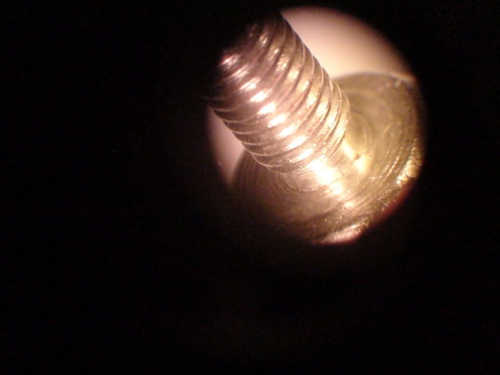
I cleaned the contacts with circuit board cleaner, then had another look under the microscope.
It looks as though there is a sleeve of copper inside the copper ring at the surface, and this has either been soldered poorly in the first place, or the solder melted due to the heat.
Here are some pictures of the rim of contact C, taken through the microscope at either 10 or 30-fold magnification:
Click image to enlarge.
Click image to enlarge.
Click image to enlarge.
Click image to enlarge.
Click image to enlarge.
Click image to enlarge.
Click image to enlarge.
Click image to enlarge.
Seeing this I decided to try to solder the "rim" back on.
I put the tiniest bit of solder onto the soldering iron, but it turned into a mountain viewed through the microscope....
Click image to enlarge.
It took a while to spread the solder around and to flatten and smooth it out.
I hope I have improved rather than worsened things with this...
But the rim looked like it would cause resistance and heating again unless I do something about it.
Here is how it progressed from there:
.
Click image to enlarge.
Click image to enlarge.
Click image to enlarge.
I believe this might work, but I lack the experience to be certain about it.
Can those of you, who have soldered similar stuff before, please comment if it is worth putting the Vectux together again, or should I rather get a professional "solderer" to have a go at it and fix that contact before reassembly?
Or how can I get a better soldering result myself?
Thanks,
Mr. Mik
This information may be used entirely at your own risk.
There is always a way if there is no other way!
Just some friendly comments...
Most electronics I see (like scooters) coming from China are "Class 1" work. I highly doubt anyone there checks their work under a microscope, especially under 30x magnification. [Class1: scooters, Class2: computers, Class3: medical/aerospace]
Your soldering. My goodness. You did so without using [enough] flux and/or heat?
Speaking of flux, that is what I think I see on your screw-in connector. Have you tried looking at the board under a UV light to see if the coating glows (might, might not)?
.
And again with your threads; could you try to keep them all in one place instead of continuously opening up more and more? These are all about the same scooter, about the same problem?
<table border="0" style="border:1px solid #999999; padding:10px;"><tr><td>
<a href="http://www.BaseStationZero.com">[img]http://visforvoltage.org/files/u419...
[size=1][color=black]www.[/color][color=#337799]BaseStationZero[/color][co
Hey Mik,
thanks first of all for making your experience with the V available to us, this could potentially be very informative and helpful to all V riders who run into technical problems!
The thing that strikes me as odd is that any circuit board, mother board or whatever would get so hot that it requires such large contact infrastructure. The discoloration is definitely a sign that circuitry is being heated way too strongly.
That's why the big heat generating items such as MOSFET's have heat sinks. My gut-feeling is that the work you're performing is not really hitting the problem at it's source (which, of course, I can't be of help in finding or determining).
If these contacts create proboems, I would create a solder terminal with large enough of solder mass to replace them entirely. Which could be tricky as you don't have lots of space to modify on that board.
Vectrix should give you a schematic of all electronics involved. That's the least they should do!
Weird stuff!
Anyways, best of luck with the attempted repairs - be careful!
Mik that soldering is appalling!!! You have not used enough heat and or flux. You should with enough heat be able to finish up with a nice even ring. Use at least a 100 watt iron and a solder sucker to remove the blobs. use fine scouring pad to clean everything and if you can get hold of a chefs blowlamp with a very fine flame that should even things out. I was taught soldering including silver soldering and brazing and I would have been shot if I tried to present a job like that. If youm haven't the tools please take it to a professional. You will get very poor conductivity and hpoor contact area trying to use the finish you have there.
Regards
Ray
Ray
.
I'll try looking at it under my mozzie catcher or water sterilizer UV lamp.
As for the multiple posts:
It's just good practice for a number of reasons. Try to read a long thread on a Pocketsurfer, for example....
And I needed to get the disclaimer issue sorted - now that you have seen my soldering, you know why!
Mr. Mik
This information may be used entirely at your own risk.
There is always a way if there is no other way!
These are the heat sinks:
A very big fan blows at them from behind, at varying speeds depending on load and temperature.
Click image to enlarge.
Mr. Mik
This information may be used entirely at your own risk.
There is always a way if there is no other way!
Thanks Ray! Much appreciated.
I have taken decisive action and told the apprentice to tidy up the workshop.
(That'll be me...)
At least until he finds the solder sucker and has created a clean workspace for the job at hand.
.
I took a cautious approach to the first soldering attempt, which I obviously have not learned yet.
My main aim was to not damage anything, as in frying the circuit board or dropping solder into the hole and ruining the thread for the stud...I have managed to avoid causing any additional damage so far!
The soldering iron I used appears to be 20W (measured it today).
I have another one, it runs on 12V and is way too powerful. It's tip goes red hot within seconds.
I do have small butane torches which could easily heat up the entire ring of solder to liquid form, but it could also heat the board quickly.
Stainless steel 5mm screws bought yesterday can keep the solder out of the hole and the threading inside it. It appears that solder does not stick to the SS bolt, just the rosin (I tried to get it to stick yesterday).
Is a stainless steel screw a good way to keep the solder out of the threading, and out of whatever is in the larger sealed compartment on the board? I cannot see if the bottom of the hole is connected to the space inside the sealed part or not.
I'll take the MC board to the local electronic shop and get some advice. The likely outcome will be that I finally get a decent soldering iron and learn how to use it.
Mr. Mik
This information may be used entirely at your own risk.
There is always a way if there is no other way!
MiK I would not use any bolt to fill the threaded hole's !! Solder likes to flow into the smallest gaps first. just find the right size threading tap , if you get any solder into the hole . for a metal (copper) piece that big I would use a gun type soldering iron 80W - 100w use ROSIN core solder , pull the triger on the gun till you get the solder to flow on the iron , than go to the part and start apply heat to the solder as it is held aginst the part as the solder flows add triger or reliece and move around till you fill the whole joint (no pun intended). afteryou fill than move around agin with no extra sloder , just watch as the solder flows around with you .! A QUICK WIPE WITH A DRY COTTEN CLOTH WILL REMOVE ANY MOLTEN EXCESS . A damp cloth held to the back side will prevent the board and sorounding airea from over heating , remember you can let go of the triger if the solder is flowing and pull it if it starts getting hard in front of you ! THIS IS ONLY ONE OPINION AND NOT TO BE TAKEN AS IN ANY WAY CERTIFIED VECTRIX REPAIR POLLITICS lATER
thank GOD I wake up above ground !!!!
This is what the structure of the connectors A and B looks like:
And this is connector C:
The little black areas in the corners are where it looks as if it was not soldered correctly or melted later on, and this is the area I try to cover with solder.
On connectors A and B it does not even look like it has been soldered in the corner, more like one piece of copper.
The diagrams are drawn according to what it looks like from the outside and when peeping into the hole.
Can anyone recognize the type of connector from the photos and the diagrams and tell me how the connectors actually look like on the inside, and where the current would leave the copper part to get to the MOSFETS or whatever else is in the sealed black box?
Does the current need to go through the conical lower copper part?
This diagram shows roughly how the connectors appear to sit in the controller board:
Click image to enlarge.
I used a pencil torch and a 30-450W soldering iron but did not get any better results than yesterday with the 25W iron.
I got better results when I put a different, conical tip on the 25W iron. This made it much easier to "pull" the solder around the circle.
It is impossible to see if the solder is bridging the gap in the corner well, but I think it does.
After the soldering I screwed the stud in repeatedly, and a few times without the washers, in order to flatten and cut the solder surface for a better fit.
I increased the torque 6Nm this time, and re-tightened several times. It appears that after a few minutes the screw can be tightened again a little bit more with the same 6Nm torque. After 3-4 times this settled.
You guys will probably still think the soldering looks like a dogs breakfast, but I am quite confident it will have good contact. I'll keep a close eye (and nose) on it....
Before screwing on:
Click image to enlarge.
After screwing on a few times:
Click image to enlarge.
Click image to enlarge.
Click image to enlarge.
Regarding the heat transmitting paste that needs to go onto the back of both the "black boxes" on the back of the board:
Is there a best way to apply it? I bought a 10ml syringe full, that should be enough.
A comb might be useful as a "notched trowel" equivalent (as used for laying tiles). Or is just zig-zaging or criss-crossing out of the syringe enough?
Or cover both sides thinly? The aim is to get an even, uninterrupted, thin film of paste between the metal plates.
Thanks for all your hints and tips, keep them coming, please!
Mr. Mik
This information may be used entirely at your own risk.
There is always a way if there is no other way!
I think you're taking this in the wrong direction, and are concerned with a part of that board which has nothing to do with your problem. I would also strongly suggest you learn soldering and all the features designed into a circuit board before you try and tackle any issues you think may have come up on this. OR, let someone else check things out for you.
Something tells me you're going to end up trashing this thing and will be asking for a refund and/or free replacement - which I can just see the distributor laughing his head off once he sees this thread. :-)
<table border="0" style="border:1px solid #999999; padding:10px;"><tr><td>
<a href="http://www.BaseStationZero.com">[img]http://visforvoltage.org/files/u419...
[size=1][color=black]www.[/color][color=#337799]BaseStationZero[/color][co
Hi Mik,
Heat sink paste.... messy! Clean off and remove all old paste. Apply about a 1cm cube in the middle of the heat sink. Using an "old" credit card, evenly spread the paste over the whole surface. Do NOT make it a very thick layer. The purists will actually polish both surfaces to ensure a perfectly flat surface and uniform metal/metal contact and the heat sink paste (usually silver based) is used like so...a small bead in the middle and then scraped off so that only the very fine scratches are filled with the paste. too little is far better than too much. BTW the soldering job looks much neater now. The reason you can re-tighten is the solder is softer than the brass/copper combination.
have fun
Ray
Ray
Great, that makes a lot of sense doing it that way. Thanks!
650V rated gloves have arrived, I hope I get it all back together again soon.
Mr. Mik
This information may be used entirely at your own risk.
There is always a way if there is no other way!
The Vectux is up and running!!
Yeeehaaa!!!
A midnight test drive of 5.6km with multiple "sniffing-stops" to detect any burning smell went well.
The side stand performs much better than in it's original condition.
The noise level is definitively reduced since the gear box adjustment.
But it's only 10degC outside, so it remains to be seen what happens when it gets warm.
Tomorrow I'm off to work with zero emissions again!!! (And maybe I'll even make it back without a tow-truck.)
Thanks to everyone who helped to make it happen!!!
The next step will be to ride it for a while with stops for sniffing every so often to detect any smoldering early.
Once I know it is running well I'll lay it on it's side and try different lubricants for the gear box until if find which one reduces the noise further.
.
Mr. Mik
This information may be used entirely at your own risk.
There is always a way if there is no other way!
That is great .
Happy riding
Herb
The Vectux has done three days of commuting and recharging without any new problems.
Now I have some time to start discussing some of the procedures done to achieve the repair:
I'll start with the battery bridging cable topic, because I am not sure if I have done that one correctly or not.
It might (or might not) be needed each time that the batteries are disconnected.
I made a system consisting of two cables, a fuse holder and a 8Mohm resistor.
This is how the cable was made:
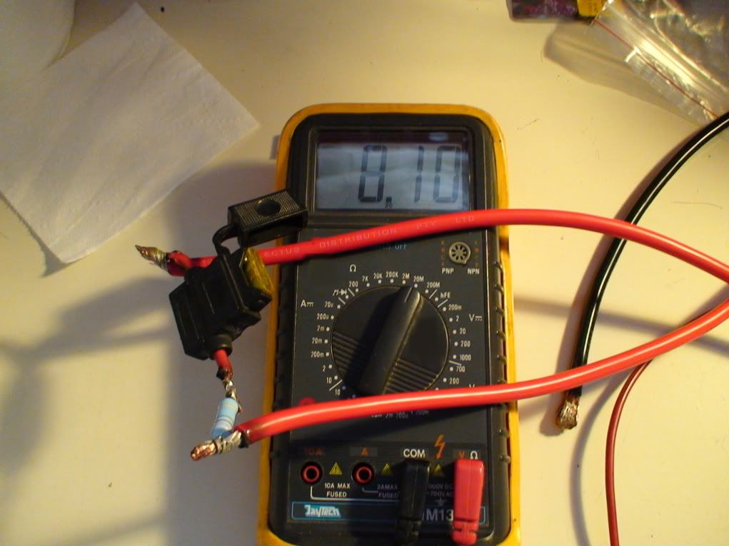
Click image to enlarge.
Click image to enlarge.
Click image to enlarge.
Click image to enlarge.
The fuse holder is used to close the circuit through the ammeter, set to measure in the 200micro-amp range.
The current between the two battery modules was measured first with the batteries only connected to each other, then with the main battery cables connected to the motor controller.
With the battery modules only connected to each other, the current was 6.8 micro-amps and remained stable for over 5min.
With the main pos and neg cables connected, the current between the batteries was 15.9 micro-amp, which remained stable for over 10min.
.
Then I connected the battery cables directly to each other and video-ed it in night-vision mode (hoping that any flash would show up particularly well).
There were two noises but no visible flash. The noises might just have been caused by the plastic connectors creaking, or it could have been a small arc. No magic or other smoke or smell....
Here is the video:
http://www.youtube.com/watch?v=RT0CU22-vek
Next time I will try this with a resistor with less resistance, or leave the 8Mohm one on for a looong time to see if anything changes.
Any ideas how to take a rational approach to this?
Mr. Mik
This information may be used entirely at your own risk.
There is always a way if there is no other way!
I decided to start testing if different lubricants can quieten the gear box down further.
(See http://visforvoltage.org/forum/3272-vectrix-real-world-testing-2-noise-levels#comment-19359 for details of preliminary changes to the gear box)
Rather than adding a bit at a time I went to the extreme and replaced the gear box oil with 100% additive, and 5 times the usual amount....
It might well lead to a range reduction due to the stiffness of the additive used, but I can always change it again....
I was told that about 80ml of lubricant is in a standard Vectrix gearbox.
I let the Vectux stand for 24hrs after the last ride, then jacked it up onto the rock and removed the rear wheel.
Then I let the lubricant run out after opening the gear box cover.
Once empty, I replaced the cover and the wheel, and put the Vectux on its side to refill the gear box.
Click image to enlarge.
I added 400ml of "Tru Blu Oil Additive".
That is the amount that fits in without overflowing when the Vectux is on its side.
Click image to enlarge.
http://www.trubluoil.com.au/Oil_Stabilizer.html
Click image to enlarge.
Make sure you clean the sealing rubber ring and put it back in properly:
Click image to enlarge.
Here you can see how thick this additive is, note the threads it pulls when the wheel is spun:
Click image to enlarge.
I hope that the noise levels and vibrations will be drastically reduced when I get to ride it (its raining right now...) and that the added resistance is negligible.
If 100% additive does not quieten things down, then at least I will know that this approach is useless, rather than trying 30%, 40% etc etc etc. and wasting a lot of time.
I could then go straight to machining better fitting planetary gears.
So far I can say that the gear box is a lot quieter when spun by hand and when the Vectux is pushed back and forth....
Mr. Mik
This information may be used entirely at your own risk.
There is always a way if there is no other way!
Man, you are just TIRELESS!
Bravo for keeping at it and posting your progress - hope this noise issue can be resolved satisfactory.
Do the electronics work (for now)?
Best of luck
GC
Mik,
As far as the "tru-blu" stuff you used in the planetary gear box - you have to be careful. Products that thicken the gear oil cause the oil to get "wrapped up" on the gears and starve the bearings of oil. Maybe the dubiously-competent Vectrix designers didn't do this, but most transmissions and gearboxes are designed with a deliberate slinging-and-gravity-flow pattern for the oil. So, staying within a specific viscosity range is important.
I learned this, way back, this the hard way - ruining the transmission mainshaft bearings, and the differential gear input bearing on a couple Toyota pickup trucks I've owned, thinking that if the specified SAE 90 gear oil was good, SAE 140 would be better.
Noisy gears are most often a result of bad bearings (too much play) even a tiny amount out of tolerance makes a big difference.
The gears may run quieter with the oil thickener for a while; then, they will get worse.
If I were you, I would replace the bearings as the first thing to try in quieting the gears, then I'd stay with recommended specified gear oil.
Paul D.
Mik, I agree with Paul D, here. The noise can also be caused by the cut of the gears, Helically cut gears are less noisy because the contact area is greater and if the contact surfaces are case hardened (for longer life)and profiled it can affect the noise. Straight cut gears are basically easier and cheaper to cut but can be cut to fine tolerances with care which can reduce noise as well. As for the lubricant. ...The reduction gear box on one of our aircraft was reported as being noisy when spun by hand. One less than competant "engineer" used a thicker grade oil instead of checking the magnetic chip detectors for debris. Result... the gearbox exploded in flight causing me a severe adrenalin rush and a change of underwear!. Cost to replace the gearbox...£23,000 pounds!!! The aircraft was a turbine Islander and I had 10 Sport parachutists on board who vacated very quickly leaving me to my own devices! I was the only one without a parachute. The explosion was caused by the oil overheating and blowing the casing apart. He hadn't realised the the oil also was used for cooling as well as lubrication.
Regards
Ray
Ray
Thanks PJD and Raytheham!
I have removed the Tru Blu. It did not get rid of the noise anyway. No objective testing was done. The gear box appeared a bit hotter than usual and the range was reduced, but that could also have been due to strong wind.
The gear box is vented:
Click any image to enlarge.
Excess lubricant comes out of there and makes a mess.....
.
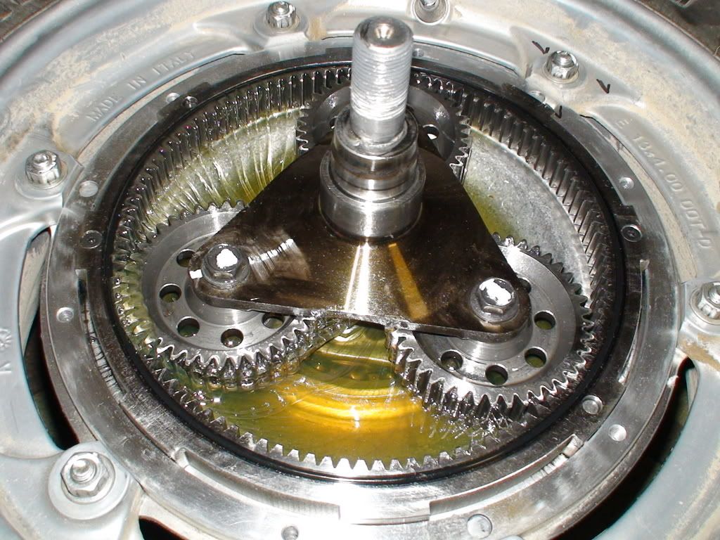
I dismantled the gear box further and washed the gears in order to enable a good look at them and proper measuring.
.
There appear to be several problems:
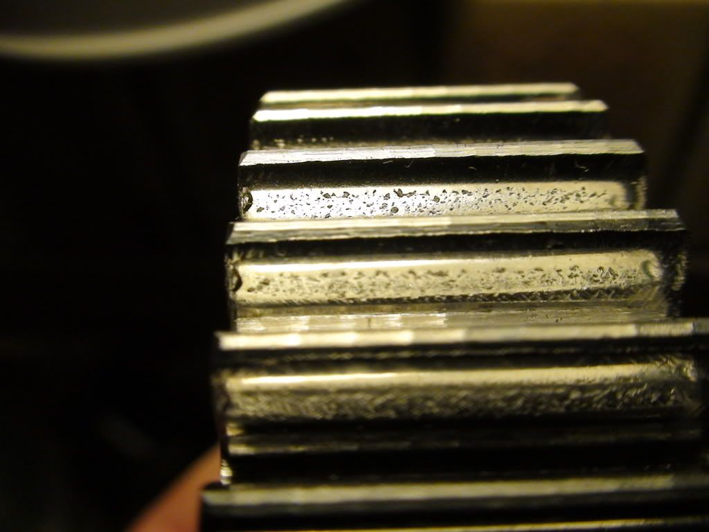
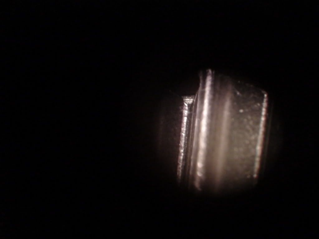
The surfaces of the planetary gears are pitted; the noisiest gear has the most pitting, the quietest the least pitting:
This is PG 1, the noisy one:
This is PG 2, the quiet one:
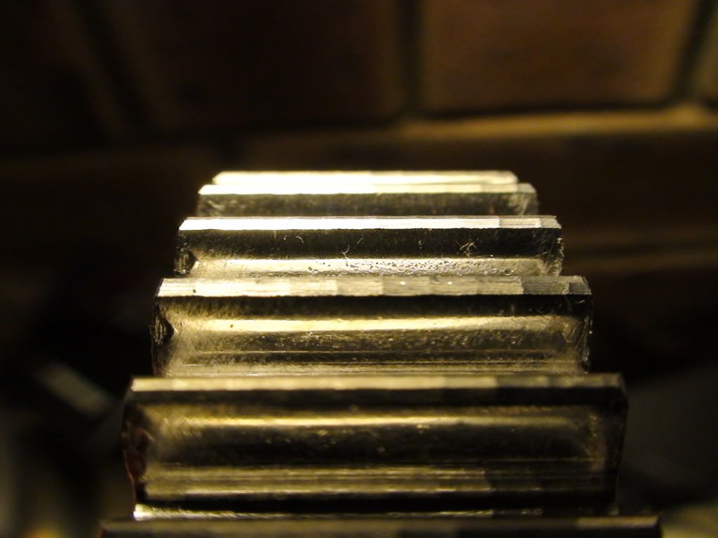
And this is PG 3, which makes a little noise:
.
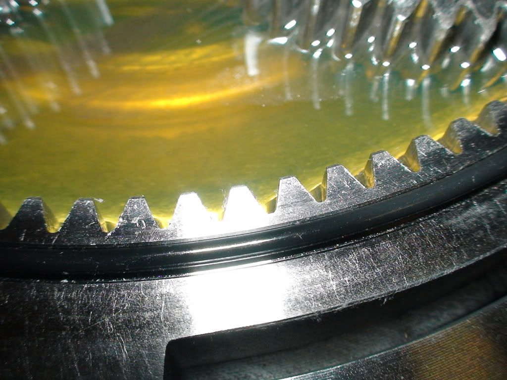
The sun gear and the ring gear show no pitting at all:
Sun gear:
.
Ring gear:
.
.
The other problem is that the ring gear is slightly oval.
I do not know if this is significant, but there is a difference of 0.18mm between the two diameters indicated by the cables crossing the gear:
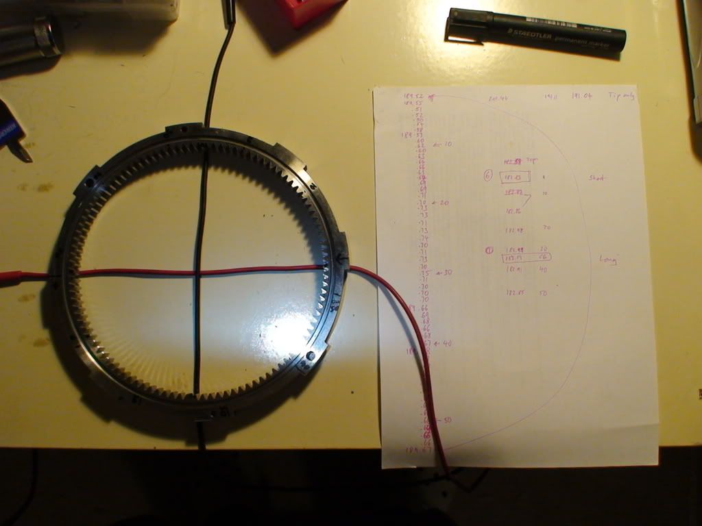
183.01mm along the black cable, 182.83 along the red cable....
I am not sure if this has anything to do with the vibrations (at 8km/h) which are synchronous with wheel rotation; I would rather expect 2 vibrations per revolution of the wheel if the oval gear was the reason.
QUESTIONS:
Is the pitting on the planetary gears the cause or the result of the noise and vibration?
Could it be possible to somehow make the ring gear round again?
.
I will probably use 65ml of Syntrax 75W/90 and 20ml of Try Blu for the next fill.
http://www.autobarn.com.au/products/10/225/1732481
Mr. Mik
This information may be used entirely at your own risk.
There is always a way if there is no other way!
Mik,
As raytheham noted, they are straight-cut gears! I didn't know they were used in gearboxes anymore - except the reverse gear in some cars.
How much of the Vectrix came from China?
Your only solution is going to be a new set of gears from Vectrix. Check the bearings too. The gear damage may be due to misalignment caused by excessive bearing play.
Mik, contact faces on straight cut gears are usually case hardened to stop this kind of wear. It looks as if the quality control failed here and it may be possible, if you know a good blacksmith/metal working shop to re-case harden the gears. This may mean re-machining the gear faces but case hardening should give you a bit longer life. The ovality in a planetary gear box is a worry. Although it is possibly within working tolerance it will certainly produce a fluctuating noise when running at speed as the different tolerances open and close.
I dont know what metal the ring gear is made of but with care and suitable clamps it should be possible to make it round without using heat. If you have to use heat then you will lose the tensile strength of the gear.
"You are a brave man gunga din"...(Kipling!) Stripping it down to this level required a lot of courage.
Regards
Ray
Ray
The planetary gears look like they are of poor quality compared to the rest of the scooter.
This is the back side of PG 1:
Click image to enlarge.
The black rough stuff that covers part of the gear does not come off with the bio-solvent I used to clean the gears. It covers part of the gear and there is less of it on the other two planetary gears.
Mr. Mik
This information may be used entirely at your own risk.
There is always a way if there is no other way!
It looks like hard, baked on oil.That will be a swine to remove. The Smooth part of the gear on the right of the picture looks as if it has been in running contact with something which could have caused it to heat up and burn the oil in contact with it. The gear itself looks cast steel then machined up. Difficult to establish quality really.
Regards
Ray
Ray
It is getting difficult to view this thread with anything but a high speed internet connection due to the many photos.
I have started at new thread at: Vectux Part 2 (= Open Source Vectrix )
"The topics in this thread are still being discussed and further input is most welcome.
Please post any contributions or questions at:
Vectux Part 3 - Vectrix with RETAMPI
Thank you!"
Thanks again,
Mr. Mik
This information may be used entirely at your own risk.
There is always a way if there is no other way!