Here is a video showing the Vectux dashboard during a very steep uphill acceleration.
It is full throttle, then two short regen braking periods. Then the view over the dash....
Notice the positive voltage reading when regen braking, negative when the battery gets drained.
-4.08V is the highest reading so far, and I believe that the power drain at about 60-80km/h uphill is the highest. But I do not have to believe or speculate any longer.
I'll review the videos I made during the rest of this demanding test drive (with the hole in the Motor Controller Board!!!) and then I will decide how to set the LED display. Link to LED description
.
.
Surfers Paradise in the distance...have not used my surfboards since this Vectrix business started, but maybe soon I'll be into the juice again with zero emissions on the way there.
The next video will show the regen braking down the same steep road.
Mr. Mik
This information may be used entirely at your own risk.
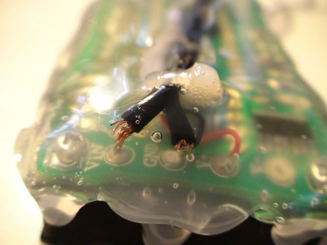
Unfortunately, not on the Vectux MC board coating:
So I drilled some more holes and put a cable tie onto it, and also covered the cable ends just in case they ever make it near anything live. The hot glue seems to be a good insulator!
Mr. Mik
This information may be used entirely at your own risk.
In this video the voltage reaches 1.84V during steep downhill regen braking.
The voltage might get higher during regen braking from full speed, it remains to be seen.
.
.
This next video shows how the Voltmeter reading fluctuates during fast downhill meandering:
After this final test I took the housing of the LED display apart and used the "rocking hot glue" liberally to water-proof it somewhat. Then sprayed on liberal amounts of PCB lacquer. Now it's drying.
Tomorrow I will add more hot glue to the back and sides to make it rugged enough to co-inhabit the glove box with whatever else I stuff in there.
.
.
.
Here is what the DMM tells during recharging:
The other videos (like off-the-line acceleration to 100km/h and regen braking back to zero) recorded today were plagued by reflections on the DMM, making it unreadable.
With the LED this will hopefully be less of a problem, but it might be blinding at night and unreadable in direct sunlight. Time will tell!
Mr. Mik
This information may be used entirely at your own risk.
My experience with hot glue leaves a lot to be desired. I have tried it several times and it does work for light items but anything with any weight to it I find it to be some what lacking in holding power. Am I doing something wrong with it?
My experience with hot glue leaves a lot to be desired. I have tried it several times and it does work for light items but anything with any weight to it I find it to be some what lacking in holding power. Am I doing something wrong with it?
Grandpa Chas S.
Well, Chas , this one is for you! A hot glue job if ever there was one....
You just don't use enough hot glue.....thats all!
But the name is misleading - I do not think I have really used it much as glue, more as a plastic filler / material that can be built up and reshaped as needed.
Wish I had a hot glue sucker, like a solder sucker, will have to make one one day.
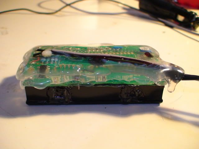
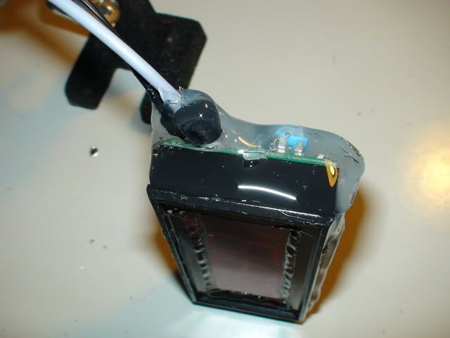
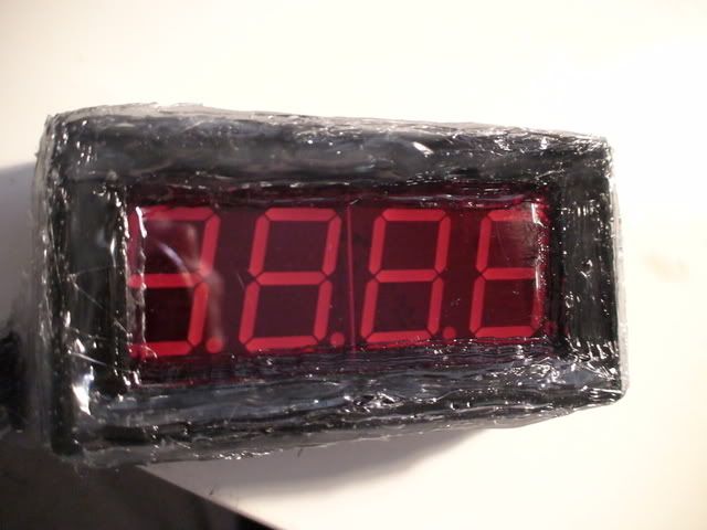
To make the RETAMPI (Real Time Amp Indicator) I started with a LED designed for use on PCB's which are kept in cosy, dry indoor conditions. I emptied the plastic housing and then put hot glue on the inside rim and replaced the red transparent plastic viewing screen.
Then I half screwed the PCB back on, filled the gap with hot glue and screwed it on tight. Then filled the other holes in the housing and sealed around the viewing plastic on the outside.
The result so far:
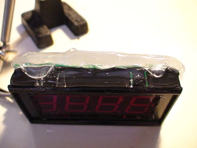
The jumpers needed to be re-soldered a few times until I got the result I wanted. Made in China including the using instructions, you know the story. I ended up setting it to 200V range and position 2 for the decimal point:
Click image to enlarge.
For the images to follow: Try your luck and click. It might work sometimes.
.
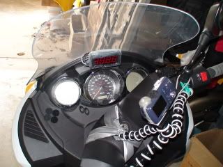
Now imagine that device on the dash or together with the 3.5kg disk brake lock in the glove box......
It wold not last long!
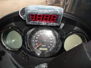
Here is how it is wired up, see above posts for details of the LED and where it is connected to the motor controller board. I calibrated it to show about -0.01V when the Vectux is only just on - not hot, no fans running, but headlight on.
.
.
.
This is inside the glove box; above the 12v outlet is the connector for the CanBus that is eagerly awaiting my attention...
.
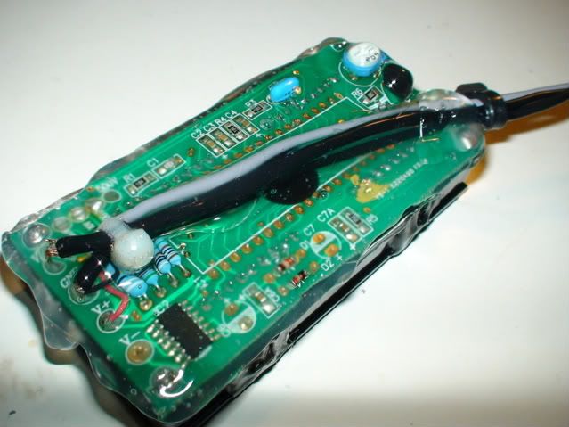
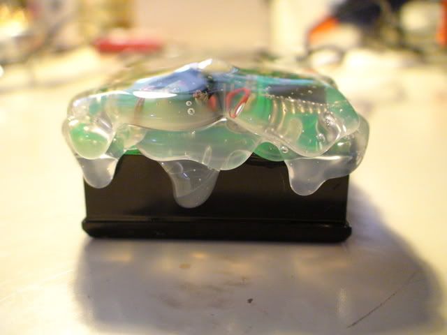
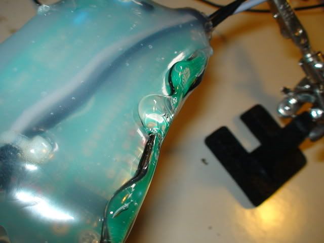
Back to the hot (glue) issue:
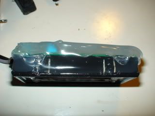
So I started to cover it in hot glue to protect it from water, impact, vibration etc.
.
.
.
.
.
.
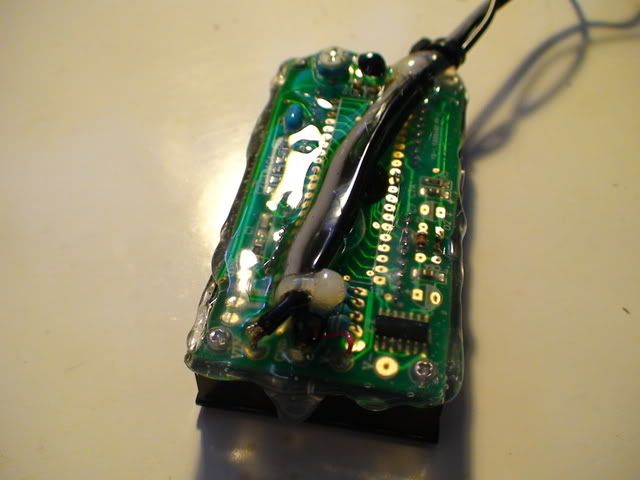
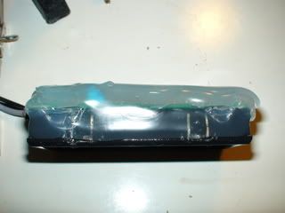
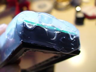
The whole process took about an hour; once the glue is cool enough it starts to become opaque.
.
Then you can lay on the next layer, it will melt the still warm stuff and bond perfectly with it.
.
.
.
.
.
.
.
.
.
.
.
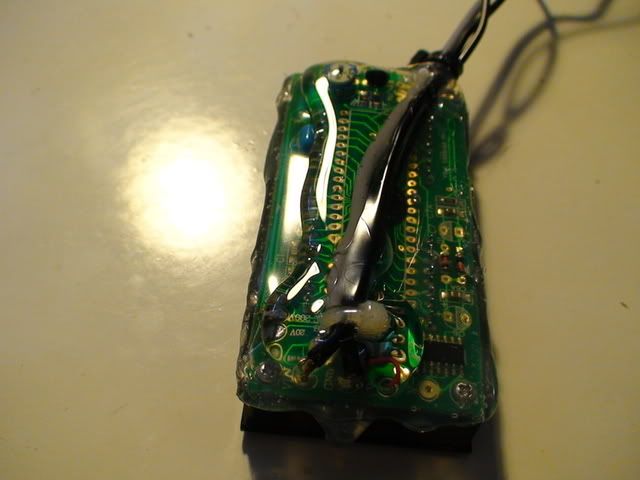
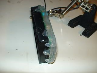
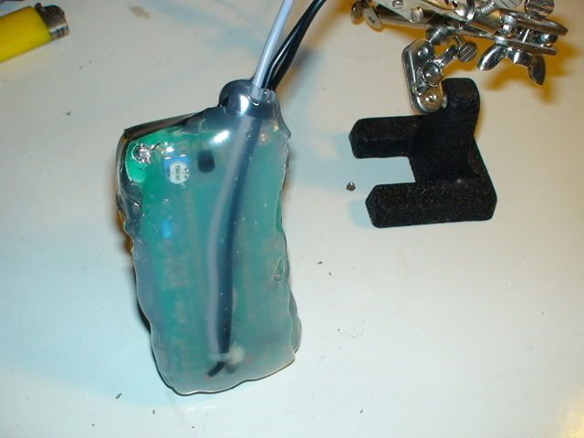
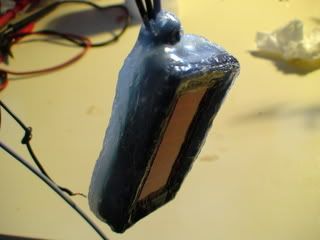
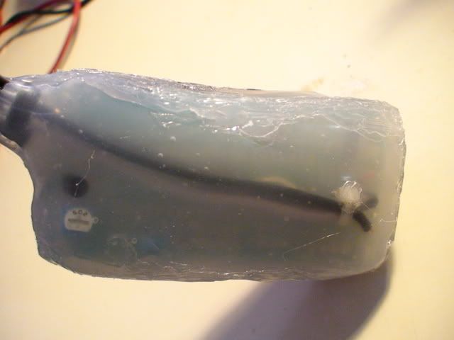
A hot air gun would probably make this look shiny and nice. But my budget is blown as it is, and the worse it looks, the better! See: http://visforvoltage.org/forum/3672-protecting-bionx-components-theft#comment-20648
. And there it was, the RETAMPI:
.
.
.
Now, if I can make it look like an alarm....
This is very true, and it happened to me once but the second time I had an alarm installed and the police made the arrest.
Grandpa Chas S.
I hope that answers all your questions about hot glue, but I only discovered it a year ago, or so...
It might melt again when the Ozzi sun has a go at it underneath the windscreen, in 45°C ambient temperature, with black plastic underneath the glue...once it gets hot it will turn clear again and increase the heat transfer - all or nothing!
But that is 5-6 months away, and by then this would be a success story even with glue all over the dash board...
And it might keep the thieves away! (By now I must admit I would be upset if someone stole the Vectux...)
I might even give it a wash soon, but only if it runs for a week without me having to debride the motor controller!
Mr. Mik
This information may be used entirely at your own risk.
Hi Mik
when the hot glue leaks and things get wet inside . go with clear silicon . it stick to ever thing and will take a lot of heat. we use it on intake and exust on combustion engine .
Hi Mik
when the hot glue leaks and things get wet inside . go with clear silicon . it stick to ever thing and will take a lot of heat. we use it on intake and exust on combustion engine .
Herb
Thanks, Herb, and I keep your previous comments about the battery recall in mind, too!
But if I had done this job with silicone, I would still be in the early stages! The RETAMPI is under cover anyways...as far as rain during riding goes.
If it buckets from behind whilst the Vectux is parked, then the RETAMPI might get wet, of course.
If it gets wet inside, then I am convinced that the job cannot be done with hot glue.
I hope it lasts!
Mr. Mik
This information may be used entirely at your own risk.
Yeah, it's not really made for bonding. What it does make is an excellent insulator that's easy to apply to uneven surfaces.
A hot air gun would make it smooth, but not all that shiny. I touch up all my hot glue work with a small propane torch, BTW. :)
Also, I'm not sure what it means, LOL. What's it calibrated for? Decimal at 10A? 100A?
The author of this post isn't responsible for any injury, disability or dismemberment, death, financial loss, illness, addiction, hereditary disease, or any other undesirable consequence or general misfortune resulting from use of the "information" contai
A hot air gun would make it smooth, but not all that shiny. I touch up all my hot glue work with a small propane torch, BTW. :)
Also, I'm not sure what it means, LOL. What's it calibrated for? Decimal at 10A? 100A?
I tried the torch, but it started smoking and I was worried it might all go up in flames...
The RETAMPI displays the voltage from the Hall-effect sensor around the main positive battery cable. The range is about -4.37V to +2.91V (the highest values I have seen so far).
Can someone make sense out of the specs for the Hall-sensor? Click here for specs sheet for the LEM HTB 200-P
I read into it that it produces a fairly accurate and linear voltage increase with increasing current going through the measured cable, but I cannot figure out how to convert the Voltage produced to the Current measured!
That spec sheet covers several models of that sensor, so it won't give a straight V per A answer. I think yours hits 4V at 500A, though.
So 2.91V should be about 360A. Sounds about right, I guess.
The author of this post isn't responsible for any injury, disability or dismemberment, death, financial loss, illness, addiction, hereditary disease, or any other undesirable consequence or general misfortune resulting from use of the "information" contai
That spec sheet covers several models of that sensor, so it won't give a straight V per A answer. I think yours hits 4V at 500A, though.
So 2.91V should be about 360A. Sounds about right, I guess.
But the fast acting, 125A fuse makes this impossible. The hall sensor is located around the positive battery cable, just between the fuse and the RGBTs.
Mr. Mik
This information may be used entirely at your own risk.
I'm looking at the "VOUT Output voltage (Analog) @ ± IPN DC, RL = 10 kΩ, TA = 25°C ± 4 V" part. The "IPN" is 200A for your model, meaning it should output 4V at 200A. 2.91V would mean 145.5A then.
The calibration on something is off, apparently. :/
EDIT: LOL, I just noticed that's Tux in your avi (high screen resolution makes it kind of small and hard to see).
The author of this post isn't responsible for any injury, disability or dismemberment, death, financial loss, illness, addiction, hereditary disease, or any other undesirable consequence or general misfortune resulting from use of the "information" contai
Building on your figuring, I assume that the Hall-effect sensor has a certain wattage that it can put out and that the specs descibed as:
VOUT Output voltage (Analog) @ ± IPN DC, RL = 10 kΩ, TA = 25°C ± 4 V
mean that the voltage of ± 4 V will be produced when 200A (IPN DC)are being measured and if the output voltage goes across a resistor of 10kΩ (across the output pins to which I have attached the cables to the RETAMPI).
Ω=V/A ---> I = 4V / 10000Ω = 0.4mA.
---> 4V * 0.4mA = 1.6mW output.
So if this Hall-effect sensor can produce 1.6mW and 4V, it should be possible to adjust the resistor so that the maximum voltage range is being used.
For example, assuming that the Vectux draws 100A max through the main battery cable, leaving a 25% safety margin for the 125A fuse, then the Hall-effect sensor would only produce a voltage of 2V.
By doubling the resistance/impedance of what ever it sends it's signal to, i.e. 20kΩ, the Vectrix engineers might have halved the current flowing but the voltage would then double again to the max 4V it can produce.
This would double the "range" of the signal output, or it's "resolution" (not sure what the correct terms are). And the signal would be easier to read and use by the 20kΩ device reading the output!
By adding the RETAMPI I have added a parallel circuit with either 10mΩ or 100mΩ (Chinese instructions, and I neglected to actually measure it so far!)
In other words, I am drawing either a 1/200th or 1/2000th of the voltage away from the device receiving the signal from the Hall-effect sensor. This amount is less than half the inaccuracies of the sensor and should be negligible.
And the Vectux runs and charges exactly as before, indeed!
I hope you can follow this hypothesis - seems to make sense to me, but please let me know if this is nonsense.
The only way that I can think of to be certain about this would be to de-solder the Hall-effect sensor, then measure the resistance. But this might not be possible if the resistance / impedance changes according to the status of the whole system, as in on or off, capacitors charged etc etc etc.
I do not really need to know the exact Amperage going in and out, anyway - just knowing where and when the maximum current draw happens, and what percentage of it is going in or out with just milliseconds delay is great!
When the RETAMPI shows -4.00 I use about 100%, at -3.00 its 75%, at -0.50 it's 12.5% etc.
And I believe that 100% means 100A with a +/- 10% margin for error, anyway.
So basically I multiply the display of the RETAMPI by 25A and assume I get the current in amps going in or out of the battery.
I have made some interesting observations and gained insights into how this scooter works using the RETAMPI and will report them later on.
Mr. Mik
This information may be used entirely at your own risk.
Hi Again Mr Mik. Yes, I think it is measuring the 200a with 4 volt indicating. I tried to work out the specs based on both sets of data and worked out if it was the 400A spec it was recording we've got deep trouble! The cables alone wouldn't handle that let alone the 125A fuse! 200a continuously rated cable is at least 1cm diameter, multi-strand and very inflexible. Curve radius is of the order of 10cm at least!
I would just use the RETAMPI as an indication of maximum current draw rather than try and calculate actual figures.
Anyway, any sign of overheating from the repair yet? Or haven't you had chance to give it blast up and down the road?
I would have put a temperature probe glued to that area to monitor it before going any further with electrical analysis.
I hope you can follow this hypothesis - seems to make sense to me, but please let me know if this is nonsense.
The only way that I can think of to be certain about this would be to de-solder the Hall-effect sensor, then measure the resistance. But this might not be possible if the resistance / impedance changes according to the status of the whole system, as in on or off, capacitors charged etc etc etc.
Of the sensor? That won't work. Resistance doesn't really come into play with a hall sensor. It outputs a voltage signal based on how much magnetic field is around it.
However, if you measure the voltage coming out of it (instead of resistance) for a known current, it would be easy to figure out its V per A ratio.
The author of this post isn't responsible for any injury, disability or dismemberment, death, financial loss, illness, addiction, hereditary disease, or any other undesirable consequence or general misfortune resulting from use of the "information" contai
Anyway, any sign of overheating from the repair yet? Or haven't you had chance to give it blast up and down the road?
I would have put a temperature probe glued to that area to monitor it before going any further with electrical analysis.
No sign of over heating yet. Commuting daily as usual, 20km x 2, but avoiding going really hard for very long. I keep the amps under 50% of max continuously on the long uphill stretch back home. That lets me travel at the speed limit of 80km/h anyway.
.
506.1km as the "Vectux" so far; 2995km total with this scooter; 1991km with the current Motor Controller Fuse (my record for a fuse so far); 171.6km since the last Motor Controller Repair (it lasted 334.5km after the first repair); and 1400km with the first Vectrix before the fuse blew and the scooter was replaced.
.
I was considering several options for temp monitoring, but none appeared suitable or safe.
Unless a probe is glued directly to the connector it would not pick up any heating because of the strong air flow caused by the cooling fans. And direct connection risks a short and electrocution.
IR sensing might work, but is tricky.
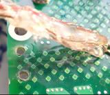
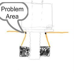
I do believe the problem is permanently fixed now. It was in all likelihood caused by the coming apart of the copper plate and copper sleeve that was between the stud and the RGBT contact of motor cable C. (see pictures below for illustration)
With 30-fold magnification:
I might open the battery compartment up again on the weekend and have a look at the motor cable contacts A, B and C without taking them apart. It can be done with a small telescopic mirror. But that would only be useful if I catch the problem just at the right time, which is unlikely. The first time the MCBoard was frying it would have been barely visible without taking the MCBoard out.
The Vectux still smells of the sick-sweet, toxic smell of the burnt MCBoard, which makes it hard to detect if there is a recurrence of mild smoldering.
But when it does smolder you cannot miss it - the first time I had a very bad cold and smelled it. The second time the whole area around the house smelled strongly and I was initially not sure if it came from the Vectux.
The Vectux still smelled bad even after removal of the burned board, and the boards smell was something else....VERY smelly.
But it is settling now.
Mr. Mik
This information may be used entirely at your own risk.
Of the sensor? That won't work. Resistance doesn't really come into play with a hall sensor. It outputs a voltage signal based on how much magnetic field is around it.
However, if you measure the voltage coming out of it (instead of resistance) for a known current, it would be easy to figure out its V per A ratio.
Thanks, Link!
What I meant was to remove the Hall-effect sensor from the board, then measure the resistance on the contacts on the board, not on the sensor.
The voltage produced by the H-E sensor will be higher if there is a higher resistance to overcome, and the current will be lower. If there was zero resistance, there would be no voltage but max induced current. With an open circuit (infinite resistance) there would be max voltage but no induced current.
Anyhow, I do not really need to know how many amps flow there for now (and there is currently no need to risk messing up the controller board).
Mr. Mik
This information may be used entirely at your own risk.
The resistance of the contacts shouldn't matter. The impedance of the voltage sensor (the RETAMPI) is what's important. It should be well into the MΩ range, so you'll be getting full voltage out of the sensor.
The author of this post isn't responsible for any injury, disability or dismemberment, death, financial loss, illness, addiction, hereditary disease, or any other undesirable consequence or general misfortune resulting from use of the "information" contai
The resistance of the contacts shouldn't matter. The impedance of the voltage sensor (the RETAMPI) is what's important. It should be well into the MΩ range, so you'll be getting full voltage out of the sensor.
I did not really mean the resistance of the contacts, but the resistance of what they connect to on the PBC. I cannot figure it out what it connects to just from the photos I took.
The RETAMPI is then connected in parallel to that impedance / resistance and the total could be calculated or measured.
.
I just took apart the RETAMPI connectors in the glove box and measured resistance:
Between the cables going to the RETAMPI: 9.8MΩ
Between the cables going to the H-E sensor: 157kΩ
I guess it means that the device that the H-E sensor connects to has a resistance of at least 157kΩ.
And that the RETAMPI has a maximum of 6.24 times the resistance of that device.
And that the RETAMPI might introduce a 16% error into the signal reported to the Vectux electronics.....
Maybe I should disconnect it!
Added 6hrs later:
My calćulations were out by a factor of ten.
Meaning: The RETAMPI has maximally 62.4 times the resistance
of the unknown deice, and introduces at least 1.5% measurement error. That's probably acceptable but can be improved.
I'll try to add in about 400Mohm in series with the RETAMPI, some of it variable.
If I'm right that should drop the Voltage across the RETAMPI into the 100mV range and make the introduced measurement error negligible.
And the variable resistor should allow fine adjustment so that the RETAMPI shows -100 when max power/amps are being used.
Mr. Mik
This information may be used entirely at your own risk.
Hi
This is for everyone . Mik had said he could put the gauge in glove box in bad weather .
That may not help . I ended up in the rain the other day. The water runs down the dash and into the glove box.
so be care full what you leave in there.
This thread has become too long and takes a long time to load due to the many pictures in it.
"The topics in this thread are still being discussed and further input is most welcome.
Please post any contributions or questions at: Vectux Part 3 - Vectrix with RETAMPI
Thank you!"
Thanks again,
Mr. Mik
This information may be used entirely at your own risk.


The ALT approach does not work, but copying/pasting the symbols out of your post works:
100kΩ
70°C
Thanks! Post some more for my collection, please!
Mr. Mik
This information may be used entirely at your own risk.
There is always a way if there is no other way!
Here is a video showing the Vectux dashboard during a very steep uphill acceleration.
It is full throttle, then two short regen braking periods. Then the view over the dash....
Notice the positive voltage reading when regen braking, negative when the battery gets drained.
-4.08V is the highest reading so far, and I believe that the power drain at about 60-80km/h uphill is the highest. But I do not have to believe or speculate any longer.
I'll review the videos I made during the rest of this demanding test drive (with the hole in the Motor Controller Board!!!) and then I will decide how to set the LED display.
Link to LED description
.

.
Surfers Paradise in the distance...have not used my surfboards since this Vectrix business started, but maybe soon I'll be into the juice again with zero emissions on the way there.
The next video will show the regen braking down the same steep road.
Mr. Mik
This information may be used entirely at your own risk.
There is always a way if there is no other way!
Unfortunately, not on the Vectux MC board coating:
So I drilled some more holes and put a cable tie onto it, and also covered the cable ends just in case they ever make it near anything live. The hot glue seems to be a good insulator!
Mr. Mik
This information may be used entirely at your own risk.
There is always a way if there is no other way!
In this video the voltage reaches 1.84V during steep downhill regen braking.
The voltage might get higher during regen braking from full speed, it remains to be seen.
.
.
This next video shows how the Voltmeter reading fluctuates during fast downhill meandering:
After this final test I took the housing of the LED display apart and used the "rocking hot glue" liberally to water-proof it somewhat. Then sprayed on liberal amounts of PCB lacquer. Now it's drying.
Tomorrow I will add more hot glue to the back and sides to make it rugged enough to co-inhabit the glove box with whatever else I stuff in there.
.
.
.
Here is what the DMM tells during recharging:
The other videos (like off-the-line acceleration to 100km/h and regen braking back to zero) recorded today were plagued by reflections on the DMM, making it unreadable.
With the LED this will hopefully be less of a problem, but it might be blinding at night and unreadable in direct sunlight. Time will tell!
Mr. Mik
This information may be used entirely at your own risk.
There is always a way if there is no other way!
My experience with hot glue leaves a lot to be desired. I have tried it several times and it does work for light items but anything with any weight to it I find it to be some what lacking in holding power. Am I doing something wrong with it?
Grandpa Chas S.
Well, Chas , this one is for you! A hot glue job if ever there was one....
You just don't use enough hot glue.....thats all!
But the name is misleading - I do not think I have really used it much as glue, more as a plastic filler / material that can be built up and reshaped as needed.
Wish I had a hot glue sucker, like a solder sucker, will have to make one one day.
To make the RETAMPI (Real Time Amp Indicator) I started with a LED designed for use on PCB's which are kept in cosy, dry indoor conditions. I emptied the plastic housing and then put hot glue on the inside rim and replaced the red transparent plastic viewing screen.
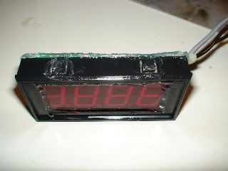
Then I half screwed the PCB back on, filled the gap with hot glue and screwed it on tight. Then filled the other holes in the housing and sealed around the viewing plastic on the outside.
The result so far:
The jumpers needed to be re-soldered a few times until I got the result I wanted. Made in China including the using instructions, you know the story. I ended up setting it to 200V range and position 2 for the decimal point:
Click image to enlarge.
For the images to follow: Try your luck and click. It might work sometimes.
.
Now imagine that device on the dash or together with the 3.5kg disk brake lock in the glove box......
It wold not last long!
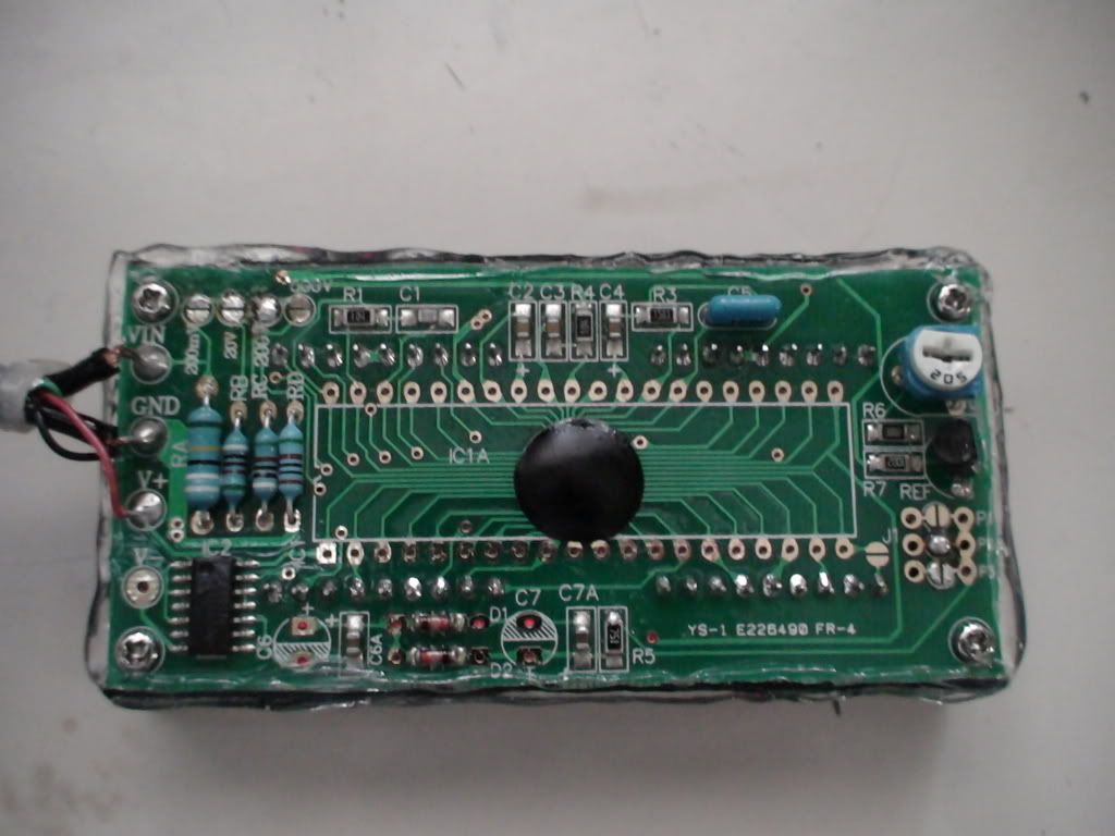
Here is how it is wired up, see above posts for details of the LED and where it is connected to the motor controller board. I calibrated it to show about -0.01V when the Vectux is only just on - not hot, no fans running, but headlight on.
.
.
.
This is inside the glove box; above the 12v outlet is the connector for the CanBus that is eagerly awaiting my attention...
.
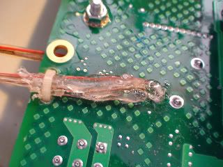
Back to the hot (glue) issue:
So I started to cover it in hot glue to protect it from water, impact, vibration etc.
.
.
.
.
.
.
The whole process took about an hour; once the glue is cool enough it starts to become opaque.
.
Then you can lay on the next layer, it will melt the still warm stuff and bond perfectly with it.
.
.
.
.
.
.
.
.
.
.
.
A hot air gun would probably make this look shiny and nice. But my budget is blown as it is, and the worse it looks, the better! See: http://visforvoltage.org/forum/3672-protecting-bionx-components-theft#comment-20648
.
And there it was, the RETAMPI:
.
.
.
Now, if I can make it look like an alarm....
I hope that answers all your questions about hot glue, but I only discovered it a year ago, or so...
It might melt again when the Ozzi sun has a go at it underneath the windscreen, in 45°C ambient temperature, with black plastic underneath the glue...once it gets hot it will turn clear again and increase the heat transfer - all or nothing!
But that is 5-6 months away, and by then this would be a success story even with glue all over the dash board...
And it might keep the thieves away! (By now I must admit I would be upset if someone stole the Vectux...)
I might even give it a wash soon, but only if it runs for a week without me having to debride the motor controller!
Mr. Mik
This information may be used entirely at your own risk.
There is always a way if there is no other way!
Hi Mik
when the hot glue leaks and things get wet inside . go with clear silicon . it stick to ever thing and will take a lot of heat. we use it on intake and exust on combustion engine .
Herb
Thanks, Herb, and I keep your previous comments about the battery recall in mind, too!
But if I had done this job with silicone, I would still be in the early stages! The RETAMPI is under cover anyways...as far as rain during riding goes.
If it buckets from behind whilst the Vectux is parked, then the RETAMPI might get wet, of course.
If it gets wet inside, then I am convinced that the job cannot be done with hot glue.
I hope it lasts!
Mr. Mik
This information may be used entirely at your own risk.
There is always a way if there is no other way!
Here is a video of the RETAMPI in action, displaying the voltage produced by the Hall-effect sensor around the main "+"cable from the battery.
Accelerating from 0-100km/h, holding 100km/h for a bit, then using regen braking back down to zero.
Let me know if you know what it all means...!!!
Mr. Mik
This information may be used entirely at your own risk.
There is always a way if there is no other way!
Whoa. That is some hardcore hot gluing. :^O
Yeah, it's not really made for bonding. What it does make is an excellent insulator that's easy to apply to uneven surfaces.
A hot air gun would make it smooth, but not all that shiny. I touch up all my hot glue work with a small propane torch, BTW. :)
Also, I'm not sure what it means, LOL. What's it calibrated for? Decimal at 10A? 100A?
The author of this post isn't responsible for any injury, disability or dismemberment, death, financial loss, illness, addiction, hereditary disease, or any other undesirable consequence or general misfortune resulting from use of the "information" contai
I tried the torch, but it started smoking and I was worried it might all go up in flames...
The RETAMPI displays the voltage from the Hall-effect sensor around the main positive battery cable. The range is about -4.37V to +2.91V (the highest values I have seen so far).
Can someone make sense out of the specs for the Hall-sensor? Click here for specs sheet for the LEM HTB 200-P
I read into it that it produces a fairly accurate and linear voltage increase with increasing current going through the measured cable, but I cannot figure out how to convert the Voltage produced to the Current measured!
Here is the link to the LED display description.
This is a Link to a video showing the RETAMPI during the beginning of recharging.
Mr. Mik
This information may be used entirely at your own risk.
There is always a way if there is no other way!
That spec sheet covers several models of that sensor, so it won't give a straight V per A answer. I think yours hits 4V at 500A, though.
So 2.91V should be about 360A. Sounds about right, I guess.
The author of this post isn't responsible for any injury, disability or dismemberment, death, financial loss, illness, addiction, hereditary disease, or any other undesirable consequence or general misfortune resulting from use of the "information" contai
But the fast acting, 125A fuse makes this impossible. The hall sensor is located around the positive battery cable, just between the fuse and the RGBTs.
Mr. Mik
This information may be used entirely at your own risk.
There is always a way if there is no other way!
I think I have it figured out.
I'm looking at the "VOUT Output voltage (Analog) @ ± IPN DC, RL = 10 kΩ, TA = 25°C ± 4 V" part. The "IPN" is 200A for your model, meaning it should output 4V at 200A. 2.91V would mean 145.5A then.
The calibration on something is off, apparently. :/
EDIT: LOL, I just noticed that's Tux in your avi (high screen resolution makes it kind of small and hard to see).
The author of this post isn't responsible for any injury, disability or dismemberment, death, financial loss, illness, addiction, hereditary disease, or any other undesirable consequence or general misfortune resulting from use of the "information" contai
Thanks, LinkofHyrule!
Building on your figuring, I assume that the Hall-effect sensor has a certain wattage that it can put out and that the specs descibed as:
VOUT Output voltage (Analog) @ ± IPN DC, RL = 10 kΩ, TA = 25°C ± 4 V
mean that the voltage of ± 4 V will be produced when 200A (IPN DC)are being measured and if the output voltage goes across a resistor of 10kΩ (across the output pins to which I have attached the cables to the RETAMPI).
Ω=V/A ---> I = 4V / 10000Ω = 0.4mA.
---> 4V * 0.4mA = 1.6mW output.
So if this Hall-effect sensor can produce 1.6mW and 4V, it should be possible to adjust the resistor so that the maximum voltage range is being used.
For example, assuming that the Vectux draws 100A max through the main battery cable, leaving a 25% safety margin for the 125A fuse, then the Hall-effect sensor would only produce a voltage of 2V.
By doubling the resistance/impedance of what ever it sends it's signal to, i.e. 20kΩ, the Vectrix engineers might have halved the current flowing but the voltage would then double again to the max 4V it can produce.
This would double the "range" of the signal output, or it's "resolution" (not sure what the correct terms are). And the signal would be easier to read and use by the 20kΩ device reading the output!
By adding the RETAMPI I have added a parallel circuit with either 10mΩ or 100mΩ (Chinese instructions, and I neglected to actually measure it so far!)
In other words, I am drawing either a 1/200th or 1/2000th of the voltage away from the device receiving the signal from the Hall-effect sensor. This amount is less than half the inaccuracies of the sensor and should be negligible.
And the Vectux runs and charges exactly as before, indeed!
I hope you can follow this hypothesis - seems to make sense to me, but please let me know if this is nonsense.
The only way that I can think of to be certain about this would be to de-solder the Hall-effect sensor, then measure the resistance. But this might not be possible if the resistance / impedance changes according to the status of the whole system, as in on or off, capacitors charged etc etc etc.
I do not really need to know the exact Amperage going in and out, anyway - just knowing where and when the maximum current draw happens, and what percentage of it is going in or out with just milliseconds delay is great!
When the RETAMPI shows -4.00 I use about 100%, at -3.00 its 75%, at -0.50 it's 12.5% etc.
And I believe that 100% means 100A with a +/- 10% margin for error, anyway.
So basically I multiply the display of the RETAMPI by 25A and assume I get the current in amps going in or out of the battery.
I have made some interesting observations and gained insights into how this scooter works using the RETAMPI and will report them later on.
Mr. Mik
This information may be used entirely at your own risk.
There is always a way if there is no other way!
Hi Again Mr Mik. Yes, I think it is measuring the 200a with 4 volt indicating. I tried to work out the specs based on both sets of data and worked out if it was the 400A spec it was recording we've got deep trouble! The cables alone wouldn't handle that let alone the 125A fuse! 200a continuously rated cable is at least 1cm diameter, multi-strand and very inflexible. Curve radius is of the order of 10cm at least!
I would just use the RETAMPI as an indication of maximum current draw rather than try and calculate actual figures.
Anyway, any sign of overheating from the repair yet? Or haven't you had chance to give it blast up and down the road?
I would have put a temperature probe glued to that area to monitor it before going any further with electrical analysis.
Regards
Ray
Ray
Of the sensor? That won't work. Resistance doesn't really come into play with a hall sensor. It outputs a voltage signal based on how much magnetic field is around it.
However, if you measure the voltage coming out of it (instead of resistance) for a known current, it would be easy to figure out its V per A ratio.
The author of this post isn't responsible for any injury, disability or dismemberment, death, financial loss, illness, addiction, hereditary disease, or any other undesirable consequence or general misfortune resulting from use of the "information" contai
No sign of over heating yet. Commuting daily as usual, 20km x 2, but avoiding going really hard for very long. I keep the amps under 50% of max continuously on the long uphill stretch back home. That lets me travel at the speed limit of 80km/h anyway.
.
506.1km as the "Vectux" so far; 2995km total with this scooter; 1991km with the current Motor Controller Fuse (my record for a fuse so far); 171.6km since the last Motor Controller Repair (it lasted 334.5km after the first repair); and 1400km with the first Vectrix before the fuse blew and the scooter was replaced.
.
I was considering several options for temp monitoring, but none appeared suitable or safe.
Unless a probe is glued directly to the connector it would not pick up any heating because of the strong air flow caused by the cooling fans. And direct connection risks a short and electrocution.
IR sensing might work, but is tricky.
I do believe the problem is permanently fixed now. It was in all likelihood caused by the coming apart of the copper plate and copper sleeve that was between the stud and the RGBT contact of motor cable C. (see pictures below for illustration)
With 30-fold magnification:
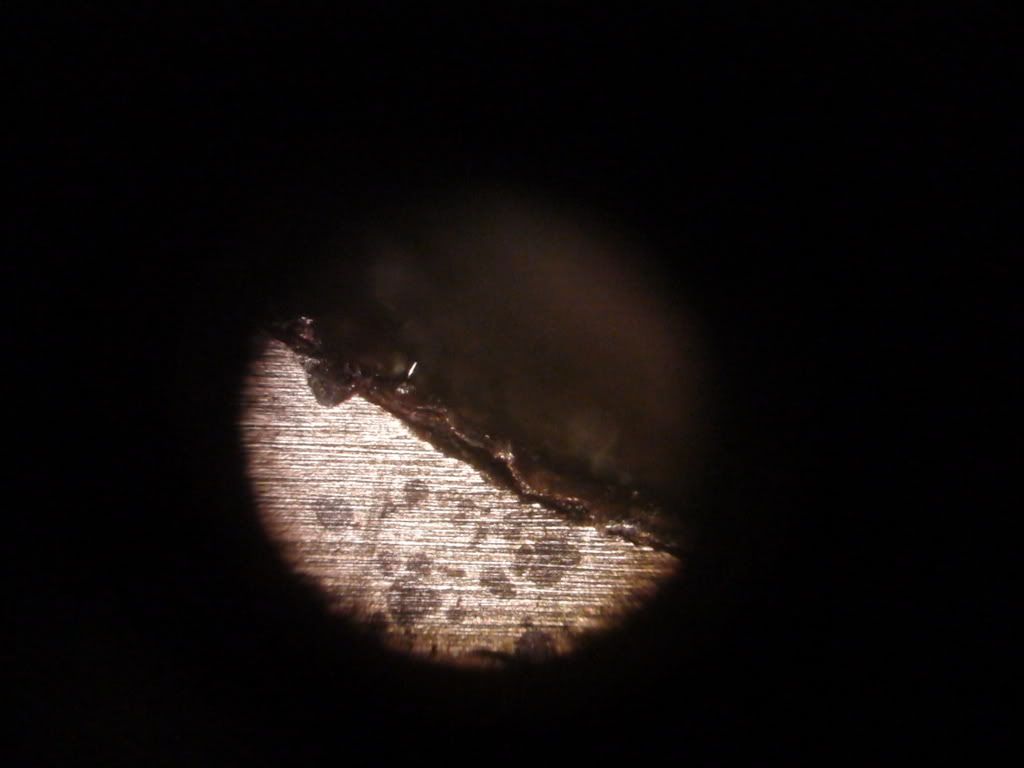
I might open the battery compartment up again on the weekend and have a look at the motor cable contacts A, B and C without taking them apart. It can be done with a small telescopic mirror. But that would only be useful if I catch the problem just at the right time, which is unlikely. The first time the MCBoard was frying it would have been barely visible without taking the MCBoard out.
The Vectux still smells of the sick-sweet, toxic smell of the burnt MCBoard, which makes it hard to detect if there is a recurrence of mild smoldering.
But when it does smolder you cannot miss it - the first time I had a very bad cold and smelled it. The second time the whole area around the house smelled strongly and I was initially not sure if it came from the Vectux.
The Vectux still smelled bad even after removal of the burned board, and the boards smell was something else....VERY smelly.
But it is settling now.
Mr. Mik
This information may be used entirely at your own risk.
There is always a way if there is no other way!
Thanks, Link!
What I meant was to remove the Hall-effect sensor from the board, then measure the resistance on the contacts on the board, not on the sensor.
The voltage produced by the H-E sensor will be higher if there is a higher resistance to overcome, and the current will be lower. If there was zero resistance, there would be no voltage but max induced current. With an open circuit (infinite resistance) there would be max voltage but no induced current.
Anyhow, I do not really need to know how many amps flow there for now (and there is currently no need to risk messing up the controller board).
Mr. Mik
This information may be used entirely at your own risk.
There is always a way if there is no other way!
Ah, I see.
The resistance of the contacts shouldn't matter. The impedance of the voltage sensor (the RETAMPI) is what's important. It should be well into the MΩ range, so you'll be getting full voltage out of the sensor.
The author of this post isn't responsible for any injury, disability or dismemberment, death, financial loss, illness, addiction, hereditary disease, or any other undesirable consequence or general misfortune resulting from use of the "information" contai
I did not really mean the resistance of the contacts, but the resistance of what they connect to on the PBC. I cannot figure it out what it connects to just from the photos I took.
The RETAMPI is then connected in parallel to that impedance / resistance and the total could be calculated or measured.
.
I just took apart the RETAMPI connectors in the glove box and measured resistance:
Between the cables going to the RETAMPI: 9.8MΩ
Between the cables going to the H-E sensor: 157kΩ
I guess it means that the device that the H-E sensor connects to has a resistance of at least 157kΩ.
And that the RETAMPI has a maximum of 6.24 times the resistance of that device.
And that the RETAMPI might introduce a 16% error into the signal reported to the Vectux electronics.....
Maybe I should disconnect it!
Added 6hrs later:
My calćulations were out by a factor of ten.
Meaning: The RETAMPI has maximally 62.4 times the resistance
of the unknown deice, and introduces at least 1.5% measurement error. That's probably acceptable but can be improved.
I'll try to add in about 400Mohm in series with the RETAMPI, some of it variable.
If I'm right that should drop the Voltage across the RETAMPI into the 100mV range and make the introduced measurement error negligible.
And the variable resistor should allow fine adjustment so that the RETAMPI shows -100 when max power/amps are being used.
Mr. Mik
This information may be used entirely at your own risk.
There is always a way if there is no other way!
Hi
This is for everyone . Mik had said he could put the gauge in glove box in bad weather .
That may not help . I ended up in the rain the other day. The water runs down the dash and into the glove box.
so be care full what you leave in there.
Happy riding , Herb
This thread has become too long and takes a long time to load due to the many pictures in it.
"The topics in this thread are still being discussed and further input is most welcome.
Please post any contributions or questions at: Vectux Part 3 - Vectrix with RETAMPI
Thank you!"
Thanks again,
Mr. Mik
This information may be used entirely at your own risk.
There is always a way if there is no other way!
Pages