How It Started
After three years of spotless performance, this June the yellow wrench lamp lit up when I not even knew an Encodr fault message existed. As suggested by Mik I hesitantly opened the encoder cover and found a lot of fine black powder.
Mixed Results From Cleaning
The first time around, I just vacuumed the interior, used window cleaner and placed back the original seal,
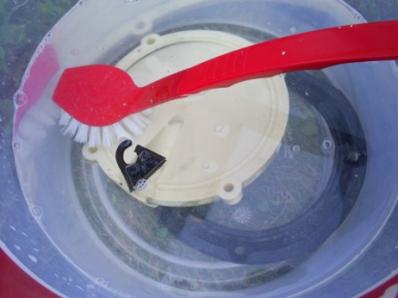
Household cleaning the encoder cover, gromet and dust seal
gromet and plastic cover. After the test drive I felt elated about the total absence of the encoder faults.
However, they quickly returned. Following Doug Townley's advice and Mik's advice, I used contact cleaner spray and compressed air
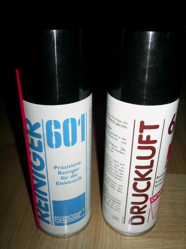
More professional cleaning
to get rid of the dirt. I also dumped the original seal and used generous amounts of silicone to close the gap around the cable. Still, black dust kept accumulating inside. I now suspect it must have come from behind the encoder disc and board, or even deeper, from inside the motor cavity. I repeated this cleaning procedure twice without lasting effect. Strangely the Encodr fault occurred only above precisely 70 km/h, at that time.
In retrospect I suspect the contact cleaner might possibly have destroyed the glue by which the slotted encoder disc is attached to its bushing (see below).
A Visit To the Dealer
Next, I ordered a replacement encoder, cover and seal. I ferried my Vectrix to a shop in Linz (some 300 km from here). Their technician was enthused about electric bikes, a Vectrix fan, and very eager to help. He replaced the encoder, the slotted disk, the cover, the seal, ran the calibration procedures, and also adjusted my throttle, and while at it replaced my handle grips. We did find that the slotted disc had almost completely come off the bushing and was hanging there by a thread. This might have caused the Encodr faults at high speeds.
The exchange procedure proved tedious enough as initially we got quite severe jerks while starting or reversing. After several trials, setting the encoder disk again on the split shaft, running the calibration several times and adjusting the throttle several times, the bike did quite ok but during the test run there still on one occasion was the Encodr fault message.
I now know (but didn't then) that the technician should have used, but didn't have available, two tools specifically designed by Vectrix for correct setting of both the slotted disc and the encoder PCB.
More Problems
I thus returned home only to experience more and more Encodr fault messages (random at any speed), and even occasional CanBus faults, as well as a mild jerk when first starting forward or reverse. I talked to Vectrix Germany and there were suggestions of exchanging the motor controller, the whole rear swing arm assembly with motor, etc. I got quotes for shipping the Vectrix to Berlin, and pondered taking the railway car ferry between Villach and Berlin,

Not me
which is a 1100 km one-way trip. Luckily (in retrospect) the German technician was unavailable during my holiday and so I postponed the trip.
Finally Some Valuable Hints
It was only Steve Scott's formidable advice over the phone that got me on the right track. According to Scott both disc and board need to be aligned to exacting tolerances. So I tried to get my hands on the diagnostic software and acquired the CANBus adapter from PEAK.
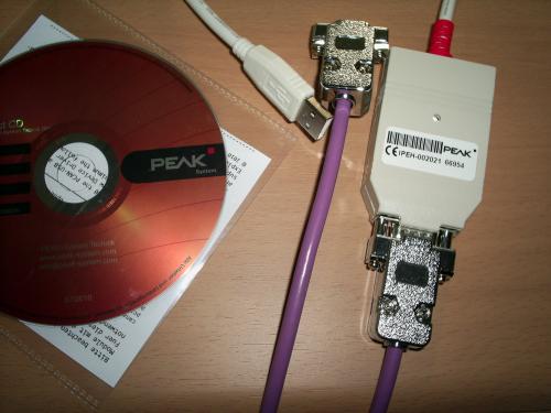
Peak shipped within 24 hrs
Studying the Encoder
It proved fortunate that I still had the "faulty" encoder board and the loose disc for study.
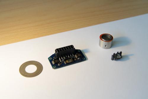
Parts removed at the dealer's
I tried to measure its dimensions, determine the required distances, and compose a technical drawing for the fabrication of calibration tools. The disc itself indeed has a thickness of only 0.1 mm.
I found six tracks on the disc:
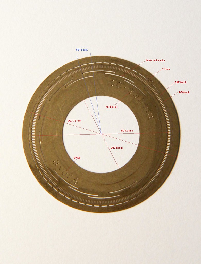
Measures are guesswork at best, don't rely on them
(from inside to outside) three Hall tracks, track A-B, and two other tracks which are apparently not used on the Vectrix. Each of these is approx 0.2 mm wide, with the exception of the A-B track which is approx 1 mm wide. The latter is used to generate two signals (A and B, respectively) which are 90º phase shifted. They are processed by the DSP on the motor controller board to determine direction of rotation (to prevent reversal when regeneratively braking), speed (I suppose there is no speed control loop, but speeds in both forward and reverse are limited), and distance traveled for the telltale. Those A and B signals could - in future firmware versions - very easily also be used for anti-locking logic during regeneration and anti-slip logic while accelerating; and of course for cruise-control.
I call the innermost three tracks Hall because in earlier servo drives these signals were generated by Hall-Effect magnetic sensors. These signals were then used for hardware control of the drive's six IGBTs, to direct current to any two of the three motor windings. Then, the sensor magnets had to be in near-perfect mechanical alignment with permanent rotor poles. Clockwork precise mechanical adjustment was required.
Instead, Vectrix designers have opted for a more sophisticated software solution. A phase shift offset is stored on the motor controller board, based on counts generated from the A-B track. On the encoder PCB there is an integrated sensor chip with six sensitive areas, corresponding to the six tracks on the disc.
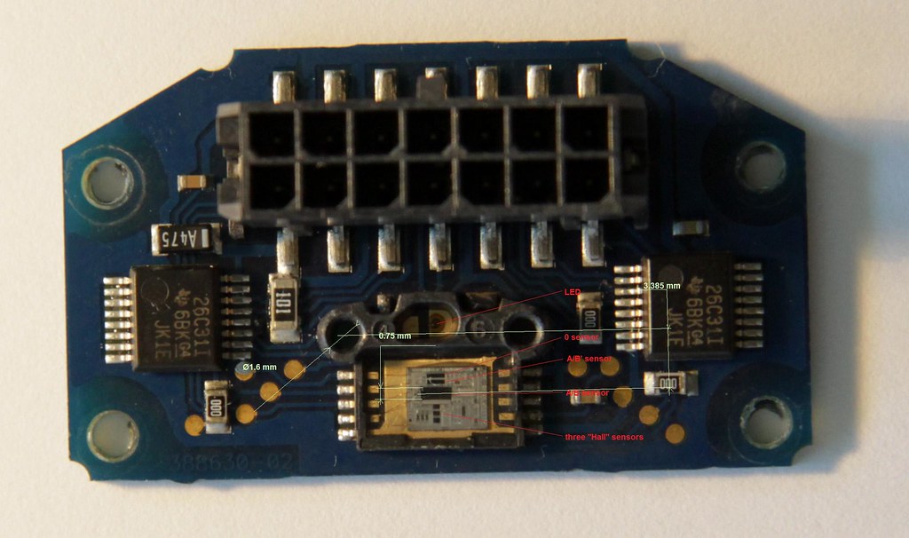
"Faulty" encoder printed board. Measures are guesswork at best, don't rely on them
The gap to the mirror/lens/prism assembly is 1.4 mm. There is however no lens in front of these sensor surfaces so I conclude the slotted disc should be positioned as close as possible, that is without scraping on the chip's plastic housing (taking into account axial clearance of the motor's bearings). Handling an offset in software makes it possible to shift the phase dynamically, compensating for winding impedance, at higher speeds.
Unknown Geometry
I strove to measure the geometry of the disc and the PCB with crude tools . Shy of using a maco camera and microscopic projector for tool adjustment it proved impossible to arrive at precise enough dimensions. In any case, the dimensions cited by Mik do not match my parts: For one, the shaft diameter is approx Ø12.5 mm on my bike, not Ø14 mm.
Installing Diagnostic Software
On my Windows XP desktop the diagnostic software 2.1 ran right away, but on my son's Windows 7 laptop one .dll was missing. He simply pulled it from the Internet by name, and presto we had contact with the Vectrix' CANBus.
Fumbling like a Brain Surgeon

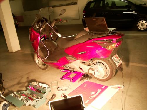
Turning my garage into a repair shop
As luck would have it, I'm fairly short-sighted, which gives me, without glasses, a sort of built-in magnifying look at close-up objects. I figured I might just be able to discern, through the slots in the encoder disc, the light sensitive areas on the chip, when correctly aligned.
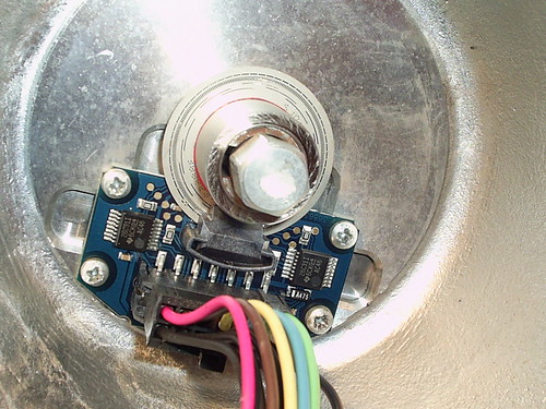
Encoder PCB still wrongly aligned to the shaft
After some training of my right eye with the damaged parts, I carefully loosened the encoder PCB on the bike, and shifted it radially from the shaft. With a flash light and staring intently I indeed saw the stars align, ie saw the darker sensor spots appear right behind the slots. The PCB might have been off by as much as 0.3 mm from its correct radial distance to the shaft.
I elected not to shift the disc axially. I can flex the disc as much as to have it touch the sensor chip's plastic rim but there definitely is no contact normally and no scraping.
Finally I ran the encoder calibration routine.
This whole exercise took just five minutes.
It Seems To Be Ok
That's how customers in remote provinces of China used to approve of the fist scrap product off a newly delivered complex fabrication line while we experts didn't yet have a clue what the heck was going on. Anyhow, during the first test run still on the jack, my bike seems to be ok.
Problem Solved
The first 150 km without Encodr messages in two months! I have a fairly good feeling that finally I also have got rid of the annoying jerks during start-up.
What We Need In the Future
What we should try to get to, is a technical drawing or a cheap source of those alignment tools. Its dimensions must be precise to tolerances no larger than ±0.02 mm. As an injection molded part it could not possibly cost more than a buck and should be packaged with each spare encoder shipped.
Another way of aligning the PCB might be by watching the encoder signals. A nice gadget would be constituted by a 9 V battery supplied test box, connected to the encoder PCB, with 5 V DC supplied and a LED display of all the five high and low signals.
Finally I don't get why Vectrix are so secretive about how to invoke the encoder calibration procedure without PC (which I still don't have a clue to). This is a great idea in the first place and would serve the Vectrix comunity well, if only it was released to the public domain.
Other Design Options
I found that 5 V supply to the encoder board is interrupted when I switch the bike off. So how can the motor controller keep track of the rotor position in case the bike is moved without power? Probably during encoder calibration the three Hall signals are also matched to the rotor poles, and their relation stored. Upon start-up this information must then be used as a crude "absolute" position, until a falling or rising edge is detected upon which the more accurate offset can be activated.
Had I been part of the design team I'd have proposed to encode absolute angular position marks on the disc. Using six tracks, this would have given about the same angular resolution within 360 electric degrees, including one parity bit. The rotational offset could have been stored on the encoder PCB, and the absolute position transmitted by CANBus to the motor controller, under the assumption of sufficient bandwith on the bus.
More pictures at: http://www.flickr.com/photos/53265378@N07/
Thanks everyone for their help and happy riding
Wolfgang


Hi Wolfgang,
great ressearch and very good post! Well service for my Vectrix is on the shedule list, so I have to visit the dealer too.
Did you bring your V to 2RadSchuller?
Greetigs Mike
P.S.: This is one of the posts being saved and printed and put to my Service-Map
Wow, my hats off to you, Wolfgang! It never ceases to amaze me what people are able to accomplish, both in regards to what the Vectrix folks put together in the first place, but most especially to what you have been able to piece together. Between you, Mik, procrastination and others, we'll soon be able to keep these bikes on the road indefinitely, or atleast until a model capable of traveling 120km/charge becomes routinely available.. ;-)
Veeeery good post, Wolfgang, thank you very much for sharing this experience with us. May I suggest you to put this in the Vectrix Collaborative Handbook ? I think it really deserve it !
I'm glad you're on the road again !
April 2010 Vectrix VX-1, 2004 Prius (feeded with E85), Giant Suede (electric bicycle)
I completely agree. Superb post, very useful!
Done.
My son dumped a MSVCR71.dll into the \Windows\system folder in order to make diagnostic software 2.1 run on Windows 7.
Wolfgang
Good reverse engineering. You are very close to the actual operation. The motor is a 12 pole motor (6 pole pairs) so there are 6 sets of "hall" sensor tracks. Commonly referred to as commutation tracks. These are absolute position tracks with 60 electrical degrees of resolution. That is, at any time, like on power up, the motor controller knows within 60 electrical degrees where the rotor is relative to the stator. This is close enough to get the motor turning in the correct direction. However, if you ran the motor only on these tracks it would not be very smooth. Once the rotor and encoder are turning, and the MC sees a transition on the comm tracks it knows exactly where the rotor is. At this point the MC starts looking at the A/B tracks, also called the incremental tracks, because it tells the MC how much the rotor has moved (as apposed to where it actually is). So from this point on the MC simply keeps track of where the rotor is by counting the A/B pulses. As you stated the tracks are offset by 90 degrees, so by looking at the phase of A/B the MC can tell which direction the rotor is turning. Whereas the comm tracks provide 60 degree resolution, the incremental tracks give a 1 degree resolution.
The MC can use both tracks to calculate fault information. For every comm track transition, there should be an exact number of incremental transitions, if not something is wrong.
The offset calibration is fairly simple. The MC locks the rotor to what it calls angle zero..by applying positive phase A current which is returned equally through phases B and C. Once stable the A/B count is zeroed, then the MC starts walking the rotor very slowly (using a lead angle of zero degrees...but this is another story). It keeps rotating the rotor until it detect the transition on the comm tracks that indicates zero degrees. The A/B count then becomes the offset. This is stored in memory.
If you pay close attention to the feel of the motor when you first turn it on and start moving you can feel the transition between using the comm tracks and the incremental tracks. You can feel it as an ever so slight rough movement until it finds itself. This takes no more than about 10 degrees of mechanical wheel rotation to occur. If you roll the bike before applying throttle it will also find itself and you will not feel it when you apply the throttle.
The encoder calibration is built into the firmware already...I sent the procedure to you a couple weeks ago...check your messages.
Dear all,
What a great post with lots of fantastic details.
I'm sorry I have to be the one who asks the stupid question. I don't fully understand the function of the encoder. What exactly does it do?
Thanks,
Jonathan
It tells the computer the exact position of the engine. With this information, the computer activates the correct magnetic field to keep the engine spinning in the right direction. The encoder is the substitute of the classic brushes.
Hi X Vectrix,
having studied some aspects of the Vectrix in detail, in my view it is a truly remarkable engineering achievement by the design team.
Could you please re-send your message to my updated address (sorry I had an outdated entry in my user profile originally)?
Thanks
Wolfgang
This is why I think I may have an encoder problem of some sort, but what I can't understand is this. All the jerky motor reversal happenings when trying to go forwards, that is the bike goes forwards then reverses then goes forwards, is all very perplexing when, after I did the PC-less recalibration of the encoder and while the bike rear wheel was off the ground the rear wheel followed the commands from the throttle perfectly, though "R" on the dash did flash on and off briefly.
I thought the problem was perhaps fixed. It was only when I lowered the bike the motor forward/reverse/forward problem returned just the same as before. This is driving me crazy as I suspect my problem is maybe easy to fix if only I knew what was causing it.
I don't really want to have to donate my Vectrix to a motorcycle museum just yet.
Do we really have no one in the UK able to service the V now, or is Steve Scott still working his magic?
Simon
You're right, it does seem a misalignment of the encoder.
There's a dealer in Ireland:
Ireland: MCC Controls http://www.mcc-controls.com/web/
Or you can ask Vectrix about his:
http://www.vectrixeurope.com/news
Your vectrix does not deserve the quietness of a museum.;-)
Alot of times, this kind of behaviour is caused by one of the encoder wires being loose. On start up the motor cant tell where it is accurately so it jumps around. Check the black connector on the encoder and make sure none of the pins have pulled out. Try pushing the scooter forward before giving it any throttle. It may be able to find itself and run correctly. If so then it is very likely to be a loose wire.