Re: How to "improve" a NiMH Vectrix battery before it ...
Hi Mik,
quite good idea, but I´m afraid if it will work in a correct way. You would need 102 cells with nearly
identical capacity AND internal resistance.
And that is exactly the definition of a good pack!
Otherwise the system might set "false alarms" when the cells
are under load... An other problem could be the temp-gradient of the twelve modules. As they are in 3
layers the bottom modules get the cool air heating it up, second layer gets heated up air heating it up
too, the third layer gets warm cooling air and/or is heated up by sun radiation. This temp. gradient might
be enough to differ the voltage as two the three packs have more 3rdlayer cells...
I cannot be very sure of what you need in Austria and other places where it gets cold. My concern is for battery temperatures from 15degC to 50degC for now.
Quite extreme values would be:
1.45V/cell under 3A charge when full at 20degC.
1.41V/cell under 3A charge when full and hot.
If only the top 7 cells (in segment 1 and 3 = the top layer of the front battery) were hot, while the rest are at 20degC, then the voltage difference would be 1.5V-1.41V= 0.09V per hot cell. Segments 1 and 3 would therefore be 7*0.09V = 0.64V lower than the voltage of the segment 2. Therefore, no false positive triggering of the IDeA would occur. Such extreme circumstances are not very likely, anyway!
The temperature gradient which you mention does indeed exist, but it would IMHO not trigger an immediate "imbalance" signal by the IDeA. The cumulative effect of repetitively occurring temperature gradients would however likely trigger the IDeA imbalance signal - but as a true positive result! This is exactly what I hope it will do.
More work but maybe more useful could be a setup where each of the 12 modules is checked, if the voltage
drops to a preset value a signal is switched on. Advantage if all 12 signals switch on the pack is empty,
if only one or two modules send a signal they may be maintained in near future...
This is in my opinion so much more difficult, because the voltages differ due to the mix of 8 and 9 cells modules and due to varying temperatures and operating conditions (like current draw). Simply comparing voltages between equal numbers of cells under all conditions should be sufficient. I might be wrong about the exact voltage difference that should be set as the trigger for the IDeA "imbalance" signal. Maybe it needs to be 0.7V for some circumstances, and 1.4V for others. But I don't think it will need to be far outside these boundaries for the vast majority of settings.
It is hard to grasp how similar the voltages of these cells are, even under load and with slightly different SOC's, if you have not watched it in action a few times. The M-BMS in the Vectux allows me to see this. I can compare the voltage of a good cell to that of a poor cells at any SOC and under any load or charge current. I know each of the 102 cells by name and number and various test results and can see that they are very very similar in voltage despite their marked capacity differences. The cells will hold almost identical voltages even if they have markedly different capacities, until they hit the empty point and go over the knee in the discharge curve. Then they drop to zero V within a few seconds. They bounce back up just as fast if the reversal was not for too long. Even the Vectux pack, with it's deliberate concentration of weak cells at the positive end of the battery, appears remarkably well balanced except when the weak cells hit empty. Most Vectrix batteries will have a much more random distribution of weaker and stronger cells, so that the IDeA should only trigger in true single cell reversal situations. The eaception to this would be when so many cells are close to reversal that they balance each other out. But the stock BMS can (and does) detect this and manages it.
A relatively simple analog op-amp circuit could measure these voltage differences all the time and in real time. The warning lamp could be wired up so that it locks "ON" whenever it is triggered for any brief period. Or it could be wired so that it only lights up when the voltage difference is present. That will allow to use the maximum possible power without reversing the weakest cell - because gentle driving is possible for a lot longer than full throttle acceleration, even if a cell is close to empty. It will always have a few Ah left that it can release at lowered current draws. In contrast to what the the stock system does when it senses an empty battery, full power would be available if the rider ssuddenly need it - but also if the warning lamp was being ignored for no good reason. However, until an imbalance problem has slowly developed to the point where it reverses a cell, the stock system would usually be limiting the power draw long before a cell reversal occurs. The IDeA is an added security that protects against undetected single cell reversal events. It would allow to avoid EQ charges for prolonged periods, therefore reducing the aging effect on the battery. You do not really need an EQ charge if you are not using the full capacity of the battery - and if no cell is beginning to reverse.
If the pack can be kept between 35-85% SOC at all times, then the increased self-discharge rate at higher SOC might be sufficient to balance the pack automatically, for the lifetime of the pack! Cells that are running between 10%-60% SOC will have less self-discharge than cells running between 40%-90% SOC. If the spontaneous self-discharge-differential between cells at 50% SOC is no larger than the differential self-discharge rate at these differential SOC's, then the SOC imbalance will only increase until it reaches a point of equilibrium. The smaller the proportion of total battery capacity which is used on a regular basis, the larger the SOC difference and spontaneous self-discharge difference could be without cell reversal occurring.
The IDeA would enable the rider to allow this process to self-limit the imbalance without any unnecessary EQ charges. About 1 or 2 EQ charges per year should be enough if long battery life is the aim.
Of course, it means that the range is usually restricted (voluntarily) to about 30km between partial charges. I think that if your regular trip distance is greater than this, then the battery will not last many years and 80,000km.
With shallow cycling and good overall care, it might even last longer than 80,000km, who knows. Worth a try, but it will take many years to prove!
This information may be used entirely at your own risk.
Re: How to "improve" a NiMH Vectrix battery before it ...
Hi Mik,
This is in my opinion so much more difficult, because the voltages differ due to the mix of 8 and 9 cells modules ...
yes you might be rigth it´s a lot of work (but the circuits can be adjusted high- and lowlevel). I was not sure how heavy temperature,
SOC-levels or differences in capacity will dropp the voltage, as I have no BMS like you. So thanks for Information! I had a "thinking-
error" with the 3x36-cell-setup as it makes no difference if you have some differences in cell capacity, the IDeA would do what it is
designed for. Another big AHA-effect for me ;-)
If you have some circuit-diagrams for your mentioned 3x36 setup, I would be interested...
Re: How to "improve" a NiMH Vectrix battery before it ...
...
...
If you have some circuit-diagrams for your mentioned 3x36 setup, I would be interested...
Greetings mike
I have no idea how to do this yet! Except maybe by using an LM324 - but that is purely because it is the only Op-amp I have ever built anything with....
I'm particularly puzzled by how to set a fixed voltage difference for the switching from high to low threshold. I know how to simply compare absolute voltage values, or how to use a voltage divider to compare fractions of voltages. I'll google it!
I'm hoping someone here might say "Just use an XYZ and hook it up like so..."
;-)
This information may be used entirely at your own risk.
Re: How to "improve" a NiMH Vectrix battery before it ...
Here is a schematic showing the stock Vectrix VX-1 voltage divider and my suggestion for where to tap into the battery to connect an independent Imbalance Detection Apparatus (IDeA):
Click for high resolution:
This information may be used entirely at your own risk.
Re: How to "improve" a NiMH Vectrix battery before it ...
Hi,
My new battery, after 4700km ridden with it, is as good as new.
My first battery was killed by the previous software. When I got the new battery, I also got the new software, so I'm riding the new battery with the new software from the beginning of it's life.
On the topic of your battery: You are an "outlier" in almost every respect. If your battery does not last, none will! Even with a broken impeller it took months to bite the dust.
The reasons:
You live in a totally flat valley and generally stay away from the surrounding mountains.
I live at the top of a steep hill. To return home I need to go up hill about 1/4 mile (about .4 km). The grade ranges between 10% and 17%. I will need to do this at low speed, roughly 10 mph (15 kph). Does this make me a poor candidate for a Vectrix? In other words is that a good reason not to purchase a Vectrix?
Keeping the sun of the battery cover is the most important part (at least in Australia). Otherwise you might get a 10-20degc temperature gradient through the battery in a couple of hours. I'm planning to apply heat reflective paint to the step-through cover.
How about a space blanket, reflective side out draped over the Vectrix, with some space for air flow?
RE: the space blanket: Been there, done that. I inserted a high-tech building insulation sarking, comprised of tough bubble-wrap between two layers of what looks like gold and aluminium, between the impeller housing and the step-through cover. But I removed it again because the surface is so electrically conductive that it is just too scary to have on an EV.
Why not get two medium weight wool or cotton blankets, one dark colored and one light colored and hire a seamstress to sew a "sandwich" with the light colored blanket on the reflective side of the space blanket and with the dark colored blanket on the non-reflective side of the space blanket. Then drape that over Vectux with the light colored blanket on the outside?
Re: How to "improve" a NiMH Vectrix battery before it ...
Hi Mik,
I decided to spend about an hour on this post because I got the impression from your reply that you didn't understand (please forgive me if that's incorrect) that large packs can be charged at the same time by using multiple isolated chargers. I have included a picture of 10 single cell isolated chargers configured to charge a 10s A123 pack. Even if you don't pursue it I hope the information will be of interest.
One way would be to use one or more of these RC chargers :
I want a way to EQ charge the entire battery safely and easily, with minimal fuss and absolutely no dismantling once the system has been installed.
A "Freddy" charger will do this nicely, the only question is how to best integrate it into the system. What cables, what fuses, diodes or not etc.
But definitively a charger that does the whole battery at once.
Using five or six iChargers simultaneously will do a better job of acomplishing what you want with a lot less fuss and hassle, with no dismantling once you get it set up correctly. You would have automated Charge, Discharge, Cycling (Charge/Discharge with user specified number of cycles) and Forming Charge. Not only would all of these functions be automated but the chargers would display the capacity of each group of subpacks (probably 2 subpacks per charger) that were charged/discharged and you would be able to export the data to logview. This will ultimately require less time and effort and less manual intervention on your part. I think the main issue is, is the increased automation, reliability and functionality worth the added cost of multiple chargers and power supplies (I have some information on inexpensive power supplies).
To use them you would only need to do the following:
Turn on one or two power strips.
Set each charger to use the same set of saved settings.
Plug in one to six charger receptacles to the matching receptacle(s) on your Vectrix.
For setup what you would do is something similar to the following (I'm using two sub packs per charger in this example, you might choose a different scheme):
Cell 1-Sub Pack 1 Neg run a wire with a receptacle
From the junction of Sub Pack 2 and 3 run two wires with receptacles, one for
connection to the plus wire of charger 1, one for the negative wire of charger 2
Repeat that process until the whole pack is wired.
It would be easiest to connect all the pack wires and charger wires into a single receptacle. Plug all the Charger Power Supplies into Powerstrip(s).
You will end up with something like the following photo of 10 single cell chargers wired to charge a 10s pack (admittedly not as compact because six chargers and six power supplies connected to six chargers are bigger than 10 single cell chargers):
You'd set up all the chargers and store the settings for the functions you want to use in their memory. The only difference in settings between chargers is that some chargers would be configured for a different number of Cells. If you don't wire them all into one receptacle you should at a minimum (IMO) wire them so that each charger pair has a single connector (dual pole Andersen's for example) and every charger configured for the same number of cells has the same connector which is different from chargers configured for a different number of cells (different sized Andersen's for example).
The following is quoted from the 1010b manual (for the 1c forming charge you might need either a bigger charger [3010b] or more chargers).
CHARGING A NICD/NIHM BATTERY
The left side of the first line displays the type of battery (NiCd/NiMH) and the
second line allows you to set the current limit. The iCharger offers two
charging modes for NiCd/NiMH., ‗CHARGE Aut‘ and ‗CHARGE Manual‘. In
‗Aut‘ mode the user sets the upper limit for the charging current. The
iCharger will charge with about 1C automatically but no higher than the
configured current. In ‗Manual‘ mode it will charge at the configured current.
Press Start/Enter for more than 3 seconds to start charging.
Current for Aut: 0.05 – 10A; Current for Manual: 0.05 – 10A
Charge status. You can stop the process at any time by pressing Batt
type/Stop. Press Dec to display the General Status information.
DISCHARGING A NICD/NIMH BATTERY
The left side of the first line shows the type of battery (NiCd/NiMH). The
value in the second line sets the discharge current on the left and final
voltage on the right. Press Start/Enter for more than 3 seconds to start
discharging.
Discharge current: 0.05 – 7A
Final voltage: 0.1 – 40.0V
Discharge status. You can adjust the discharge current by pressing
Start/Enter during the process. Press Inc or Dec to increase or
decrease the charge current. After you alter the current value, store it by
pressing Start/Enter again. You can stop the process at any time by
pressing Batt type/Stop. Press Dec to display the General Status
information.
CHARGE-TO-DISCHARGE & DISCHARGE-TO-CHARGE CYCLE MODE FOR A NICD/NIMH BATTERY
The left side of the first line shows the type of battery (NiCd/NiMH) and the
right shows the cycle number. The second line shows the cycle direction
you selected: (CHG(xxx)->DCHG)or DCHG->CHG(xxx)). You can set
the charge mode as ―Charge Auto‖ or ―Charge Manual‖. The discharge
parameters are those set in NiCd/NiMH discharge screen. Press
Start/Enter for more than 3 seconds to start the cycling.
Cycle number: 1 – 10
Cycle charge mode: „Aut‟ or „Man‟
The screen displays the NiCd/NiMH cycle mode. On the left side of the
second line, in the process is identified as either C>D or D>C. A blinking ―C‖
indicates charging, while a blinking ―D‖ indicates discharging.
You can stop the cycling process at any time by pressing Batt type/Stop.
Press Inc to display the cycle history (see the balance voltage information
& cyclic information) and press Dec to display the General Status
information.
During the waiting time of discharge-to-charge cycle mode, you can stop
the waiting process by pressing ―Start" button for three seconds!
NICD/NIMH FORMING CHARGE
THIS FORMING CHARGE PROGRAM AIMS TO ELIMINATE CAPACITY IMBALANCE BETWEEN CELLS IN A BATTERY.
The iCharger first charges with constant current (CC=1C) according to the user setting. When the charging voltage reaches the peak threshold (1.48V/cell) it switches to the CV phase. In the CV phase the current gradually falls. When the current drops to C/4 the iCharger will charge another 25% Capacity at C/10 current and then terminate the process.
The left side of the first line shows the type of battery (NiCd/NiMH). The
value on the left side of second line sets the cell capacity and the value on
the right side of second line sets the cell count and nominal voltage of the
battery pack. Press Start/Enter for more than 3 seconds to start charging.
Forming capacity: 0.1 – 9.9Ah
Cell count: 1 – 25S
Forming status. You can stop the process at any time by pressing Batt
type/Stop, and display the General Status information by pressing Dec
button.
Note: In the first period (CV charging), it displays ‖CHG‖/‖FRM‖ alternately
in Work State. It will display ‖FRM‖ when in the second period (CC
charging).
Re: How to "improve" a NiMH Vectrix battery before it ...
Hi Mik,
I decided to spend about an hour on this post because I got the impression from your reply that you didn't understand (please forgive me if that's incorrect) that large packs can be charged at the same time by using multiple isolated chargers. I have included a picture of 10 single cell isolated chargers configured to charge a 10s A123 pack. Even if you don't pursue it I hope the information will be of interest. ...
...
...
Thanks Mitch!
I know that some chargers are truly isolated and can be used this way. But this setup is in my opinion not safe and not simple for several reasons.
1): It requires dismantling of the entire battery pack to enable all those tabs to be connected.
2): The tabs cannot be protected with diodes. That means that they either leave the battery safety container and introduce electrocution risk, or they remain inside the container (like the tabs in the Vectux M-BMS) - but then it would be a major job to open the container and plug in the chargers.
If you use a single HV charger, then the tabs can be diode protected and therefore safely accessible outside of the safety container!
This information may be used entirely at your own risk.
Re: How to "improve" a NiMH Vectrix battery before it ...
Hi Mik,
If you have an answer or knowledgeable opinion about the following I'd really appreciate a reply!:
I live at the top of a steep hill. To return home I need to go up hill about 1/4 mile (about .4 km). The grade ranges between 10% and 17%. I will need to do this at low speed, roughly 10 mph (15 kph). Does this make me a poor candidate for a Vectrix? In other words is that a good reason not to purchase a Vectrix?
Hi. I have a friend who attended several times to the "Travesse dels Alps" with his prius, in Europe. This amazing electric "race" goes trough a 2800m mountain pass in the Alps, a nightmare road with constant grade over 15%. He told me that all vectrix made it to the top, but several chinese scooters got their engines burned. By the way, I've never heard of a burned vectrix engine in this forum.
If you careful drive it below 50 km/h during 0.4 km, it shouldn't be a problem. Lower speed is ok. The vectrix is powerful enough to carry you up. However, I consider you a poor candidate for any electric vehicle: Before purchasing an EV, I suggest you prearrange a place to plug before your home's uphill (bar restaurant, friend), in case you ever run out of juice... With low battery you can ride 15 km at low speed on flat roads, but you won't make it to the top of a mountain.
Re: How to "improve" a NiMH Vectrix battery before it ...
I live at the top of a steep hill. To return home I need to go up hill about 1/4 mile (about .4 km). The grade ranges between 10% and 17%. I will need to do this at low speed, roughly 10 mph (15 kph). Does this make me a poor candidate for a Vectrix? In other words is that a good reason not to purchase a Vectrix?
climbing 17% at 15kmh would need around the same power (so amps at the battery) as holding 70kmh on the flat.
the Vectrix should be fine with that load IMO.
Matt
Daily Ride:
2007 Vectrix, modified with 42 x Thundersky 60Ah in July 2010. Done 194'000km
Re: How to "improve" a NiMH Vectrix battery before it ...
Hi Mik,
If you have an answer or knowledgeable opinion about the following I'd really appreciate a reply!:
I live at the top of a steep hill. To return home I need to go up hill about 1/4 mile (about .4 km). The grade ranges between 10% and 17%. I will need to do this at low speed, roughly 10 mph (15 kph). Does this make me a poor candidate for a Vectrix? In other words is that a good reason not to purchase a Vectrix?
I have a similar problem. And it may be a problem if you plan to arrive home with an empty battery. You cannot make it up the driveway without good motor power. If you ride the VX-1 until it can only maintain 40km/h on flat ground, then it cannot climb even a mild hill any longer, let alone your driveway!
You would need to always come home with a very wide reserve battery capacity margin - unless you have a charge point at the bottom of your drive.
A 400m extension chord may be too much when you are on 120V AC supply....
You will not even be able to hold the VX-1 on your driveway when you release the brakes - I have tried it. It will just push you down backwards, it is very very heavy!
That is one of the main reasons why I would like it if we can develop a semi-automated system to do the deep discharge/exercise cycling with the bike parked. And if other topics could largely be discussed in other threads....so we can get some work done here.
So here we go back onto topic:
I made a schematic to show the principle of the setup that I have in mind. I call it the "Vectux A-BMS", for Auxiliary-BMS:
CLICK TO ENLARGE.
Can anyone come up with a circuit for the IDeA that will switch off the power to the ABCool once more than about 0.8V difference is detected between any of the three x 34 cell segments? It is represented by a relay in the schematic, but that is of course not enough.
This information may be used entirely at your own risk.
Re: How to "improve" a NiMH Vectrix battery before it ...
Hi there,
here is a little circuit I found on the web:
The Code for those who want to see how it works on the CircuitSimulatorAplet Link
$ 1 5.0E-6 10.20027730826997 50 5.0 50
v 528 288 528 192 0 2 40.0 1.0 74.0 0.0 0.5
v 528 384 528 288 0 0 40.0 75.0 0.0 0.0 0.5
w 528 288 448 288 0
t 384 240 448 240 0 1 -73.24096878564579 0.4425298938439393 250.0
t 272 288 336 288 0 1 -0.2920346544592328 0.59302513322888 100.0
t 384 336 448 336 0 -1 73.24096878564481 -0.44252989384417346 250.0
w 384 240 336 240 0
w 336 272 336 240 0
w 384 336 336 336 0
w 336 336 336 304 0
r 336 240 336 192 0 35000.0
r 336 336 336 384 0 35000.0
r 272 288 272 240 0 2000.0
r 272 288 272 336 0 4700.0
w 336 240 272 240 0
w 336 336 272 336 0
r 448 224 448 176 0 2500.0
r 448 352 448 400 0 2500.0
162 448 128 448 176 1 2.1024259 1.0 0.0 0.0
162 448 400 448 448 1 2.1024259 1.0 0.0 0.0
w 528 384 528 448 0
w 528 448 448 448 0
w 528 192 528 128 0
w 528 128 448 128 0
w 336 192 336 128 0
w 336 128 448 128 0
w 336 384 336 448 0
w 336 448 448 448 0
w 448 256 448 288 0
w 448 320 448 288 0
w 400 432 416 432 0
o 1 64 0 35 80.0 0.05 0 -1
o 0 64 0 35 160.0 0.0125 1 -1
Here the circuit:
here at "on"status as one pack has 75v and the other 73v (it would work with 74v too)
Ignore the squarewave it is the second battery pending between 73 and 75 Volt
( I didn´t want to switch the voltage manualy). The circuit activates the LED of the
battery with the higher voltage and therefore tries to equalize the two parts of the
pack at a very low rate (20 mA) but the signals of the LEDs can be used in any other
way (they are switched off when the sub-packs are equal.
Its only a rather raw prototype and unfortunately it can only compare two but not three parts of a
battery, but maybe it´s a beginning. Because it is only tested in a simulator (not build yet)values
for the resistors might be incorrect.
Maybe someone could improve the circuit that it works with three parts of the battery.
I tried to modify the circuit but it would cause an inbalance of the pack and is useless.
Re: How to "improve" a NiMH Vectrix battery before it ...
Hi, sorry the last post was quite a latenightshow and I was rather unconcentrated...
So here we go... maybe ;-)
parts of the circuit are two single battery-cells or 2 parts of the vectrix battery, 2 transistors
for the signal (LED) and a 3rd transistor. As I understand the circuit, if the two cells are equal
the third transistor blocks the two other one by taking the curent so that the two transistors don´t
have enough energy to switch on the LEDs. If on of the cells or battery part has a higher voltage
this causes a higher curent on one half of the circuit enabling one of the LED-transistor to turn on.
So the circuit gives a signal which of the two cells has a higher volage and even tries to equalize
the pack by taking more energy from the part with a higher voltage.
The circuit draws about 1 mAh when the cells are equall and 1 mAh from the lower cell but 20 mAh from
the higher cell when the LED is on. Again I did not build it I only simulated it.
more later, my train reaches my hometown...
back again!
I tried a setup for three packs or cells, it worked but unfortunately this setup causes inbalance as
it draws 1 mAh from the both cells "outside" but 2 mAh from the cell in the midle whihc is absolutly
not satisfying. It would try to balance the pack again when the "medium" cell would be discharged
enough and the LEDs of the outside cells would be switched on discharging theese cells and lowering
them to the medium cellon but it is not very elegant in my opinion.
Sorry if misspelling and gramar issues are more today, had two braindraining days at the company in
Vienna I work for...
Re: How to "improve" a NiMH Vectrix battery before it ...
Hi Mikemitbike,
Just a comment on your observations on the circuit diagram.
The current out of the top cell (1mA) plus the current out of the lower cell (1mA) are added together for the 'return' current which is the 2mA going into the junction of the two cells (this should actually measure zero as the two separate currents should be in opposing directions and equal to each other.
Result is that the total current drawn from the two cells is only 1mA per cell. However, when the circuit lights an L.E.D. the current will rise to that required by the L.E.D.
From the circuit shown the L.E.D. in the lower circuit lights up when the voltage in the upper circuit drops, this means that the low voltage cell is NOT further drained by the indicating L.E.D. but is in fact virtually switched out of circuit.
Incidentally, this circuit could be easily modified to draw less current if that were necessary.
In answer to Mik's question, this circuit compares the voltages of the two cells. Provided both cells are of equal voltage neither of the L.E.D's lights up. When one cell voltage differs from the other, then one of the L.E.D's lights up, powered by the good (higher voltage) cell. This will give an indication of imbalance between two cells.
It makes an interesting starting point for a 'low voltage cell' sensing system.
Re: How to "improve" a NiMH Vectrix battery before it ...
Hi The Laird,
thank you for the help in describing what the circuit do and how it works. Is there a posibility to
modify/improve it that 3 cells are compared to each other? The only way I was able to try was to
attach a second identical circuit, so that cell 1 and 2 are compared by circuit "a" and cell 2 and
3 are compared by circuit "b". It worked in this configuration, 1 mA were drained from cell 1 and 3
but 2 mA were drained from cell 2 as it has to suply both circuits. it would not completely inbalance
the 3 cells because the system stabilises itself: The voltage of cell 2 is lowered because of the
higher drain, but as the voltage is lowered enough the circuits power on the LEDs of cell 1 and 2
as they have a higher voltage. At the end all cells are drained equal but the medium cell has a
lower voltage (~0,4V in simulation) and the LEDs of cell 1 and 3 are maybe glowing a bit.
Greetings Mike
Edit:
that is the layout for three cells. There will be a better solution I hope but I have no idea right
now! Imput and help by people with better circuit planing skills are very very wellcome ;-)
Re: How to "improve" a NiMH Vectrix battery before it ...
...
...
that is the layout for three cells. There will be a better solution I hope but I have no idea right now! Imput and help by people with better circuit planing skills are very very wellcome ;-)
Sorry I cannot help you much there! I still have not managed to really understand how this circuit works but I nevertheless think it may be missing an essential part.
We need a circuit that only lights the LED (or does whatever else it is meant to do) when the voltage imbalance reaches a set value.
For the 3 x 34 cell segment proposed for the IDeA you would have something like 1.2V x 34 / 34 = 1.2V vs. 1.2V x 33 /34 = 1.165V.
Can this circuit be made so that it ignores up to 1.2V - 1.165V = 35mV voltage difference between the cells?
A few mV difference are to be expected, particularly if there is a temperature gradient through the battery.
This information may be used entirely at your own risk.
Re: How to "improve" a NiMH Vectrix battery before it ...
Hi folks,
I have just posted on the topic of 'How would you diagnose, test and restore a Vectrix battery'.
I think that this topic and the other thread are beginning to overlap as it all comes down to the same thing which is keeping the Vectrix (Vectux in Mik's case) going despite the battery failings due to a variety of causes.
I will repeat that post here for your information.
Hi Mik et al,
The rust on terminals. Yes, I have seen it before and it was due to saltwater ingress prior to the 'holes' in the front frame being covered with tape. The saltwater could have been sea spray on the roads or salted roads during freezing roads conditions.
Clean off the rust and apply a little lanolin / vaseline / petroleum jelly and all will be well.
Capacitor failure, is usually due to a dielectric breakdown through the application of excess voltages (transient voltage 'spikes' etc). With very high value, low internal resistance types (the type that the Vectrix has) the capacitor can be damaged by the sudden application of high voltage. This causes excessively high current to flow into the capacitor and the connecting leads simply burn out. Damage is usually instantaneous and irreparable. It is unlikely that the capacitors would fail in use because the currents in and out of the capacitor (when in use) would be very considerably less than the connection surge mentioned earlier.
Back to the original topic, identifying a battery with faulty cells/ damaged battery.
I have read many of the posts and given the matter some thought. It has occurred to me that we should step back and consider some older strategies. With lead acid batteries, the test for a 'faulty' battery was to place a high current resistor accross the terminals and observe the voltage. If the voltage dropped within a few seconds OR the voltage was low generally, then the battery was 'unfit for service'. The battery would be given a charge to 'fill it up' and the test was again applied. If the voltage dropped again within a few seconds, then the battery was condemned as unfit for service and had to be replaced.
Now, applying the same idea to the Vectrix battery, we have a battery of which we know the terminal voltage and the internal resistance. We know the open circuit voltage at full charge and we can calculate the volt drop at the terminals when a known load ( fixed/known resistance) is applied. We also know that if any cell(s) is/are not 'up to the job' there will be additional voltage drop. Preliminary calculations produce the following results.
(using a Cell resistance of 0.0012mOhms)
102 cells will drop 0.1224 volts per ampere of discharge.
At 10 amperes discharge the volt drop will be 1.224 volts.
At 20 amperes discharge the volt drop will be 2.448 volts.
At 30 amperes discharge the volt drop will be 3.672 volts.
This pattern continues.
If a faulty cell is present or if the battery is in a low state of charge, then the volt drop will be greater than expected.
For every cell which is empty there will be an extra drop in the voltage.
Therefore what is needed is a simple way to load the battery with a fixed resistance and a means of measuring the relatively small voltage drop without the other 125 or so volts obscuring our view. This is not as difficult as it sounds and I already have a circuit design which could make the required voltage drop easy to observe.
The difficulty with this method is in the application of the resistive load. One way of doing this which might work is to apply the brakes and use full throttle to give a fixed current drain on the battery. One would need to know a) that the Motor control unit would not be damaged by this (it shouldn't as it is only a stalled take off and would only last for a few seconds) and b) exactly what current would this draw from the battery.
If anyone thinks that there is something here of interest, then I will produce working drawings of the circuit I have in mind and you/we can give it a whirl.
Re: How to "improve" a NiMH Vectrix battery before it ...
Hi folks,
I have just posted on the topic of 'How would you diagnose, test and restore a Vectrix battery'.
I think that this topic and the other thread are beginning to overlap as it all comes down to the same thing which is keeping the Vectrix (Vectux in Mik's case) going despite the battery failings due to a variety of causes.
I will repeat that post here for your information.
...
...
Great to see you are chipping in!
The topics do indeed overlap, but in this thread I hope to find solutions that keep a good battery just like that - good!
In the other thread I try to figure out how to best diagnose if it is good, what parts are damaged - and how to fix it.
.
Today I came across an otherwise poor post on a Prius forum that gave me an idea regarding the IDeA (Imbalance Detection Apparatus): It is quite likely that the Toyota Prius NHW10 battery-ECU does just that - detect imbalance by somehow measuring the voltages of 20 modules of 12 cells each in a serial NiMH battery of 240 cells. Maybe a closer look at that B-ECU will give us an idea for the comparatively simple Vectux-IDeA with just 3 modules?
In a few days I should have a damaged Prius B-ECU back from attempted error code wiping - that one will lend itself to destructive analysis and testing....
In the meantime, I have many more detailed photos if anyone would like to have a closer look at them.
This information may be used entirely at your own risk.
Re: How to "improve" a NiMH Vectrix battery before it ...
I hope so, because even though there was 19°C in the garage in the hottest of summer, when I did a 'to the red battery discharge' after one year I got a new battery, the battery reached 31°C-33°C at the final - CC phase.
It went like this:
- I ended the ride at 26°C with 2°C rise from the start of the ride. I was 2kms away from home when the red battery telltale appeared.
- I included 1.5 hours of pre-charge cooling. It cooled the battery down to 24°C in 1 hour then rested for 1/2 hour.
- CP Charging began at 23°C and ended at 25°C
- At the end of 15 minute TR (0 Amps, only cooling) period, the battery temperature was 26°C
- CC lasted for 1 hour and 10 minutes. The battery temperature rose from 26°C to 31°C
- After it finished CC it started 2nd TR (0 Amps, only cooling)
- I disconnected the plug since I didn't want it to do any 4 hour EQ
After I turned on the bike, I checked for the battery temperature and it was already 33°C, so I went for a night ride to consume the top 3 bars. It was 15°C outside. The battery temperature dropped to 32°C in 15kms, then I drove home and plugged to bike for pre-charge cooling only. After it cooled down the battery to 24°C I disconnected the plug and let the bike rest until morning ride to work.
This was the only time, with this new battery, that I reached 30+°C and that happened at the end of CC phase. All my other rides and charging are below 30°C. Right now it's between 14°C-20°C.
Re: How to "improve" a NiMH Vectrix battery before it ...
when I did a 'to the red battery discharge' after one year I got a new battery, the battery reached 31°C-33°C at the final - CC phase.
my experience: after reaching red battery light NEVER let it charge to full. The system tries to insert more energy than real store capacity. It unnecessarily overheats/damages the battery. Interrupt it at half charge, ride it some few km, and after some hours/day of cooling down, you can charge it to full.
About he Rav-E... It is quite astonishing that the RAV-E didn't had any BMS... The vectrix problem is just bad ventilation?
Re: How to "improve" a NiMH Vectrix battery before it ...
During testing of a used Vectrix battery on the garage floor I had opportunity to check if the comparison of voltages between the proposed three IDeA segments (of 34 cells each) will detect reversal of a single cell - and it does!
The first cell to reverse had a capacity of around 29Ah under C/5 = 6A current drain. It turned out that the voltage of the reversing cell drops to about -250mV, then slowly rises again. I stopped it after a few seconds.
The other cells were still at around 1.2V under that load, so the voltage difference between the three IDeA segments was about 1.4V.
The affected cell is the only one with visible swelling in the top layer of the battery. Because the lower two layers cannot be seen without dismantling, I can only assume that the cells in there must be better than the swollen cell and are most likely not swollen. I'll check if I ever take the battery apart.
I think this means that checking for swelling is the most sensitive and easy method of detecting bad cells in a Vectrix battery. That is consistent with my findings in the Vectux battery, where all the worst cells were swollen - and none of the good cells were swollen. See: https://www.endless-sphere.com/forums/viewtopic.php?f=14&t=6277&start=30#p102644 for details.
IDeA segments:
1: 39.95V
2: 41.33V
3: 41.36V
Module 4 cell voltages:
Cell 28: 1.214V
Cell 29: 1.214VV
Cell 30: -0.217V
Cell 31: 1.216V
Cell 32: 1.199V
Cell 33: 1.212V
Cell 34: 1.212V
Cell 35: 1.212V
I take this as confirmation that the approach with just three segments to monitor for single cell reversal would work well - but we need some IDeA to find this 1.4V difference. A 1V difference should also be sufficient as the trigger difference.
.
.
However, the presence of this single (slightly) damaged cell in this battery - and in a most convenient location in the top front battery - brought back another NiMH battery management idea: The "Sacrificial Cell". See http://visforvoltage.org/forum/8553-sacrificial-cell-easiest-bms-there .
.
. If no-one comes up with an automated IDeA for 3 battery segments, then I might build a manual BMS using the sacrificial cell as well as the three 34-cell segments:
Part A of the M-BMS: An automatic voltage detector that monitors only the sacrificial cell. It would light up a warning LED if the voltage of the sacrificial cell drops below maybe 1V. During automated deep discharge mode it could be used to automatically terminate the discharge. This device must have a very low current draw from the sacrificial cell.
A 1mA current drain from the sacrificial cell would cause 24h * 30days * 3months = 2160mAh SOC imbalance between the sacrificial cell and the rest of the pack. That means the range would be reduced by 2.16Ah / 30Ah = 7.2% after three months, taking the lighting of the warning lamp as the end of the available range. The aging effect of deep discharges upon the good cells of the pack would however be further reduced by this growing imbalance.
Part B of the M-BMS: High-value-resistor protected tab wires to the 4 IDeA tabs, connected to a switch and connection point for a DMM. This would allow periodic manual checking that the sacrificial cell is indeed still the weakest cell in the pack. The procedure would be to monitor the voltage of segments 2 and 3 while driving with near-empty battery with a DMM strapped to the handlebar. The warning lamp (from Part A) should come on before imbalance appears between segment 2 and 3. Then, confirm the voltage drop in segment 1 by switching to this segment and reading the DMM at the time the warning lamp comes on again.
Part C of the M-BMS: Diode protected charge wires to the sacrificial cell. This might be needed after occasional whole-pack EQ charging. Because the sacrificial cell is likely to slowly fall behind in SOC, one would have to over-charge the entire battery with the amount of SOC that the sacrificial cell has fallen behind. Instead of inflicting this damaging over-charge on the battery, one could perform a Freddy EQ charge (maybe every three months) until all good, standard cells are full. The diode protected charge wires would then be used to top-up the sacrificial cell until it is also completely full. That avoids any unnecessary damage to the good cells.
This information may be used entirely at your own risk.
Re: How to "improve" a NiMH Vectrix battery before it ...
If no-one comes up with an automated IDeA for 3 battery segments, then I might build a manual BMS using the sacrificial cell as well as the three 34-cell segments:
Hi there,
I had some time to think about the circuit I mentioned some posts above (Mon, 09/27/2010 - 16:24). As there is still the problem that the
medium part of the battery is discharged twice as fast as the other two parts, I addet two resistors to discharge part one and part three
as fast as the medium one. It is still a kind of crutch but it works in simulation quite well. The circuit should not disbalance the parts of the
battery too much.
If using some opto-isolators, the two one for the medium part of the battery could be combined for lightning just one LED on the dashboard
or switching one relais etc. in sum there would be 3 LEDs or relais standing for the three parts of the battery.
Another option would be to use 4 relais (or one with 4 chanels) which would be turned to "close" position via the 12V Plug in the glovebox.
So the circuit would be turned off when the Scooter is not used/charged.
Warning: This is still a simulation so the vallues for the transistors and the resistors might be wrong, parts of the circuit might have voltage
which can hurt you seriously!
Re: How to "improve" a NiMH Vectrix battery before it ...
...
...
What do you think about it?
Greetings Mike
Fabulous!
I finally took the courage to click around in that "Applet"...what a great tool! It makes it sooo easy to understand what happens! This circuit behaves very nicely indeed in the simulation.
This information may be used entirely at your own risk.
Re: How to "improve" a NiMH Vectrix battery before it ...
Hi Mik,
my first reaktion was something like "what the hell..." I opened the links after that and had a big surprise: If yo compare the
two originalcircuits you see they are nearly identical in form and funktion. "Only" difference the one uses transistros to drive
the LEDs , the other uses only LEDs driving themselve. Both circuits have the problem that they are designed to work with only
two battery parts. As I did some testing with the transistor-type, there is a little problem with switching the relais: if they
don´t switch exactly at the same time the circuit reacts and draws much more curent destroying the LEDs, so the next step will be
a constant-curent subcircuit for each LED (with a transistor or a FET (Feldeffekttransistor)).constant curent circuits (german)


And that is exactly the definition of a good pack!
I cannot be very sure of what you need in Austria and other places where it gets cold. My concern is for battery temperatures from 15degC to 50degC for now.
Quite extreme values would be:
1.45V/cell under 3A charge when full at 20degC.
1.41V/cell under 3A charge when full and hot.
If only the top 7 cells (in segment 1 and 3 = the top layer of the front battery) were hot, while the rest are at 20degC, then the voltage difference would be 1.5V-1.41V= 0.09V per hot cell. Segments 1 and 3 would therefore be 7*0.09V = 0.64V lower than the voltage of the segment 2. Therefore, no false positive triggering of the IDeA would occur. Such extreme circumstances are not very likely, anyway!
The temperature gradient which you mention does indeed exist, but it would IMHO not trigger an immediate "imbalance" signal by the IDeA. The cumulative effect of repetitively occurring temperature gradients would however likely trigger the IDeA imbalance signal - but as a true positive result! This is exactly what I hope it will do.
This is in my opinion so much more difficult, because the voltages differ due to the mix of 8 and 9 cells modules and due to varying temperatures and operating conditions (like current draw). Simply comparing voltages between equal numbers of cells under all conditions should be sufficient. I might be wrong about the exact voltage difference that should be set as the trigger for the IDeA "imbalance" signal. Maybe it needs to be 0.7V for some circumstances, and 1.4V for others. But I don't think it will need to be far outside these boundaries for the vast majority of settings.
It is hard to grasp how similar the voltages of these cells are, even under load and with slightly different SOC's, if you have not watched it in action a few times. The M-BMS in the Vectux allows me to see this. I can compare the voltage of a good cell to that of a poor cells at any SOC and under any load or charge current. I know each of the 102 cells by name and number and various test results and can see that they are very very similar in voltage despite their marked capacity differences. The cells will hold almost identical voltages even if they have markedly different capacities, until they hit the empty point and go over the knee in the discharge curve. Then they drop to zero V within a few seconds. They bounce back up just as fast if the reversal was not for too long. Even the Vectux pack, with it's deliberate concentration of weak cells at the positive end of the battery, appears remarkably well balanced except when the weak cells hit empty. Most Vectrix batteries will have a much more random distribution of weaker and stronger cells, so that the IDeA should only trigger in true single cell reversal situations. The eaception to this would be when so many cells are close to reversal that they balance each other out. But the stock BMS can (and does) detect this and manages it.
A relatively simple analog op-amp circuit could measure these voltage differences all the time and in real time. The warning lamp could be wired up so that it locks "ON" whenever it is triggered for any brief period. Or it could be wired so that it only lights up when the voltage difference is present. That will allow to use the maximum possible power without reversing the weakest cell - because gentle driving is possible for a lot longer than full throttle acceleration, even if a cell is close to empty. It will always have a few Ah left that it can release at lowered current draws. In contrast to what the the stock system does when it senses an empty battery, full power would be available if the rider ssuddenly need it - but also if the warning lamp was being ignored for no good reason. However, until an imbalance problem has slowly developed to the point where it reverses a cell, the stock system would usually be limiting the power draw long before a cell reversal occurs. The IDeA is an added security that protects against undetected single cell reversal events. It would allow to avoid EQ charges for prolonged periods, therefore reducing the aging effect on the battery. You do not really need an EQ charge if you are not using the full capacity of the battery - and if no cell is beginning to reverse.
If the pack can be kept between 35-85% SOC at all times, then the increased self-discharge rate at higher SOC might be sufficient to balance the pack automatically, for the lifetime of the pack! Cells that are running between 10%-60% SOC will have less self-discharge than cells running between 40%-90% SOC. If the spontaneous self-discharge-differential between cells at 50% SOC is no larger than the differential self-discharge rate at these differential SOC's, then the SOC imbalance will only increase until it reaches a point of equilibrium. The smaller the proportion of total battery capacity which is used on a regular basis, the larger the SOC difference and spontaneous self-discharge difference could be without cell reversal occurring.
The IDeA would enable the rider to allow this process to self-limit the imbalance without any unnecessary EQ charges. About 1 or 2 EQ charges per year should be enough if long battery life is the aim.
Of course, it means that the range is usually restricted (voluntarily) to about 30km between partial charges. I think that if your regular trip distance is greater than this, then the battery will not last many years and 80,000km.
With shallow cycling and good overall care, it might even last longer than 80,000km, who knows. Worth a try, but it will take many years to prove!
This information may be used entirely at your own risk.
There is always a way if there is no other way!
Hi Mik,
yes you might be rigth it´s a lot of work (but the circuits can be adjusted high- and lowlevel). I was not sure how heavy temperature,
SOC-levels or differences in capacity will dropp the voltage, as I have no BMS like you. So thanks for Information! I had a "thinking-
error" with the 3x36-cell-setup as it makes no difference if you have some differences in cell capacity, the IDeA would do what it is
designed for. Another big AHA-effect for me ;-)
If you have some circuit-diagrams for your mentioned 3x36 setup, I would be interested...
Greetings mike
I have no idea how to do this yet! Except maybe by using an LM324 - but that is purely because it is the only Op-amp I have ever built anything with....
I'm particularly puzzled by how to set a fixed voltage difference for the switching from high to low threshold. I know how to simply compare absolute voltage values, or how to use a voltage divider to compare fractions of voltages. I'll google it!
I'm hoping someone here might say "Just use an XYZ and hook it up like so..."
;-)
This information may be used entirely at your own risk.
There is always a way if there is no other way!
I think the name for the inner workings of the IDeA is a "Window Comparator" aka "Limit Comparator".
Like this one: http://www.intersil.com/data/an/an9802.pdf
I might be totally wrong about this....
This information may be used entirely at your own risk.
There is always a way if there is no other way!
Here is a schematic showing the stock Vectrix VX-1 voltage divider and my suggestion for where to tap into the battery to connect an independent Imbalance Detection Apparatus (IDeA):
Click for high resolution: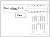
This information may be used entirely at your own risk.
There is always a way if there is no other way!
Hi,
I live at the top of a steep hill. To return home I need to go up hill about 1/4 mile (about .4 km). The grade ranges between 10% and 17%. I will need to do this at low speed, roughly 10 mph (15 kph). Does this make me a poor candidate for a Vectrix? In other words is that a good reason not to purchase a Vectrix?
Why not get two medium weight wool or cotton blankets, one dark colored and one light colored and hire a seamstress to sew a "sandwich" with the light colored blanket on the reflective side of the space blanket and with the dark colored blanket on the non-reflective side of the space blanket. Then drape that over Vectux with the light colored blanket on the outside?
Best Wishes!
Mitch
Hi Mik,
I decided to spend about an hour on this post because I got the impression from your reply that you didn't understand (please forgive me if that's incorrect) that large packs can be charged at the same time by using multiple isolated chargers. I have included a picture of 10 single cell isolated chargers configured to charge a 10s A123 pack. Even if you don't pursue it I hope the information will be of interest.
Using five or six iChargers simultaneously will do a better job of acomplishing what you want with a lot less fuss and hassle, with no dismantling once you get it set up correctly. You would have automated Charge, Discharge, Cycling (Charge/Discharge with user specified number of cycles) and Forming Charge. Not only would all of these functions be automated but the chargers would display the capacity of each group of subpacks (probably 2 subpacks per charger) that were charged/discharged and you would be able to export the data to logview. This will ultimately require less time and effort and less manual intervention on your part. I think the main issue is, is the increased automation, reliability and functionality worth the added cost of multiple chargers and power supplies (I have some information on inexpensive power supplies).
To use them you would only need to do the following:
Set each charger to use the same set of saved settings.
Plug in one to six charger receptacles to the matching receptacle(s) on your Vectrix.
For setup what you would do is something similar to the following (I'm using two sub packs per charger in this example, you might choose a different scheme):
From the junction of Sub Pack 2 and 3 run two wires with receptacles, one for
connection to the plus wire of charger 1, one for the negative wire of charger 2
Repeat that process until the whole pack is wired.
It would be easiest to connect all the pack wires and charger wires into a single receptacle. Plug all the Charger Power Supplies into Powerstrip(s).
You will end up with something like the following photo of 10 single cell chargers wired to charge a 10s pack (admittedly not as compact because six chargers and six power supplies connected to six chargers are bigger than 10 single cell chargers):
You'd set up all the chargers and store the settings for the functions you want to use in their memory. The only difference in settings between chargers is that some chargers would be configured for a different number of Cells. If you don't wire them all into one receptacle you should at a minimum (IMO) wire them so that each charger pair has a single connector (dual pole Andersen's for example) and every charger configured for the same number of cells has the same connector which is different from chargers configured for a different number of cells (different sized Andersen's for example).
The following is quoted from the 1010b manual (for the 1c forming charge you might need either a bigger charger [3010b] or more chargers).
Best Wishes!
Mitch
Thanks Mitch!
I know that some chargers are truly isolated and can be used this way. But this setup is in my opinion not safe and not simple for several reasons.
1): It requires dismantling of the entire battery pack to enable all those tabs to be connected.
2): The tabs cannot be protected with diodes. That means that they either leave the battery safety container and introduce electrocution risk, or they remain inside the container (like the tabs in the Vectux M-BMS) - but then it would be a major job to open the container and plug in the chargers.
If you use a single HV charger, then the tabs can be diode protected and therefore safely accessible outside of the safety container!
This information may be used entirely at your own risk.
There is always a way if there is no other way!
Hi Mik,
If you have an answer or knowledgeable opinion about the following I'd really appreciate a reply!:
Best Wishes!
Mitch
Hi. I have a friend who attended several times to the "Travesse dels Alps" with his prius, in Europe. This amazing electric "race" goes trough a 2800m mountain pass in the Alps, a nightmare road with constant grade over 15%. He told me that all vectrix made it to the top, but several chinese scooters got their engines burned. By the way, I've never heard of a burned vectrix engine in this forum.
If you careful drive it below 50 km/h during 0.4 km, it shouldn't be a problem. Lower speed is ok. The vectrix is powerful enough to carry you up. However, I consider you a poor candidate for any electric vehicle: Before purchasing an EV, I suggest you prearrange a place to plug before your home's uphill (bar restaurant, friend), in case you ever run out of juice... With low battery you can ride 15 km at low speed on flat roads, but you won't make it to the top of a mountain.
climbing 17% at 15kmh would need around the same power (so amps at the battery) as holding 70kmh on the flat.
the Vectrix should be fine with that load IMO.
Matt
Daily Ride:
2007 Vectrix, modified with 42 x Thundersky 60Ah in July 2010. Done 194'000km
I have a similar problem. And it may be a problem if you plan to arrive home with an empty battery. You cannot make it up the driveway without good motor power. If you ride the VX-1 until it can only maintain 40km/h on flat ground, then it cannot climb even a mild hill any longer, let alone your driveway!
You would need to always come home with a very wide reserve battery capacity margin - unless you have a charge point at the bottom of your drive.
A 400m extension chord may be too much when you are on 120V AC supply....
You will not even be able to hold the VX-1 on your driveway when you release the brakes - I have tried it. It will just push you down backwards, it is very very heavy!
That is one of the main reasons why I would like it if we can develop a semi-automated system to do the deep discharge/exercise cycling with the bike parked. And if other topics could largely be discussed in other threads....so we can get some work done here.
So here we go back onto topic:
I made a schematic to show the principle of the setup that I have in mind. I call it the "Vectux A-BMS", for Auxiliary-BMS:
Can anyone come up with a circuit for the IDeA that will switch off the power to the ABCool once more than about 0.8V difference is detected between any of the three x 34 cell segments? It is represented by a relay in the schematic, but that is of course not enough.
This information may be used entirely at your own risk.
There is always a way if there is no other way!
Hi there,
here is a little circuit I found on the web:
The Code for those who want to see how it works on the CircuitSimulatorAplet Link
$ 1 5.0E-6 10.20027730826997 50 5.0 50
v 528 288 528 192 0 2 40.0 1.0 74.0 0.0 0.5
v 528 384 528 288 0 0 40.0 75.0 0.0 0.0 0.5
w 528 288 448 288 0
t 384 240 448 240 0 1 -73.24096878564579 0.4425298938439393 250.0
t 272 288 336 288 0 1 -0.2920346544592328 0.59302513322888 100.0
t 384 336 448 336 0 -1 73.24096878564481 -0.44252989384417346 250.0
w 384 240 336 240 0
w 336 272 336 240 0
w 384 336 336 336 0
w 336 336 336 304 0
r 336 240 336 192 0 35000.0
r 336 336 336 384 0 35000.0
r 272 288 272 240 0 2000.0
r 272 288 272 336 0 4700.0
w 336 240 272 240 0
w 336 336 272 336 0
r 448 224 448 176 0 2500.0
r 448 352 448 400 0 2500.0
162 448 128 448 176 1 2.1024259 1.0 0.0 0.0
162 448 400 448 448 1 2.1024259 1.0 0.0 0.0
w 528 384 528 448 0
w 528 448 448 448 0
w 528 192 528 128 0
w 528 128 448 128 0
w 336 192 336 128 0
w 336 128 448 128 0
w 336 384 336 448 0
w 336 448 448 448 0
w 448 256 448 288 0
w 448 320 448 288 0
w 400 432 416 432 0
o 1 64 0 35 80.0 0.05 0 -1
o 0 64 0 35 160.0 0.0125 1 -1
Here the circuit:

here at "on"status as one pack has 75v and the other 73v (it would work with 74v too)
Ignore the squarewave it is the second battery pending between 73 and 75 Volt
( I didn´t want to switch the voltage manualy). The circuit activates the LED of the
battery with the higher voltage and therefore tries to equalize the two parts of the
pack at a very low rate (20 mA) but the signals of the LEDs can be used in any other
way (they are switched off when the sub-packs are equal.
Its only a rather raw prototype and unfortunately it can only compare two but not three parts of a
battery, but maybe it´s a beginning. Because it is only tested in a simulator (not build yet)values
for the resistors might be incorrect.
Maybe someone could improve the circuit that it works with three parts of the battery.
I tried to modify the circuit but it would cause an inbalance of the pack and is useless.
Greetings Mike
Thank you for this - but, could you please try to explain what the circuit is supposed to do?
I am nowhere near sophisticated enough to be able to just figure it out by just looking at the schematic, unfortunately.
This information may be used entirely at your own risk.
There is always a way if there is no other way!
Hi, sorry the last post was quite a latenightshow and I was rather unconcentrated...

So here we go... maybe ;-)
parts of the circuit are two single battery-cells or 2 parts of the vectrix battery, 2 transistors
for the signal (LED) and a 3rd transistor. As I understand the circuit, if the two cells are equal
the third transistor blocks the two other one by taking the curent so that the two transistors don´t
have enough energy to switch on the LEDs. If on of the cells or battery part has a higher voltage
this causes a higher curent on one half of the circuit enabling one of the LED-transistor to turn on.
So the circuit gives a signal which of the two cells has a higher volage and even tries to equalize
the pack by taking more energy from the part with a higher voltage.
The circuit draws about 1 mAh when the cells are equall and 1 mAh from the lower cell but 20 mAh from
the higher cell when the LED is on. Again I did not build it I only simulated it.
more later, my train reaches my hometown...
back again!
I tried a setup for three packs or cells, it worked but unfortunately this setup causes inbalance as
it draws 1 mAh from the both cells "outside" but 2 mAh from the cell in the midle whihc is absolutly
not satisfying. It would try to balance the pack again when the "medium" cell would be discharged
enough and the LEDs of the outside cells would be switched on discharging theese cells and lowering
them to the medium cellon but it is not very elegant in my opinion.
Sorry if misspelling and gramar issues are more today, had two braindraining days at the company in
Vienna I work for...
Hi Mikemitbike,
Just a comment on your observations on the circuit diagram.
The current out of the top cell (1mA) plus the current out of the lower cell (1mA) are added together for the 'return' current which is the 2mA going into the junction of the two cells (this should actually measure zero as the two separate currents should be in opposing directions and equal to each other.
Result is that the total current drawn from the two cells is only 1mA per cell. However, when the circuit lights an L.E.D. the current will rise to that required by the L.E.D.
From the circuit shown the L.E.D. in the lower circuit lights up when the voltage in the upper circuit drops, this means that the low voltage cell is NOT further drained by the indicating L.E.D. but is in fact virtually switched out of circuit.
Incidentally, this circuit could be easily modified to draw less current if that were necessary.
In answer to Mik's question, this circuit compares the voltages of the two cells. Provided both cells are of equal voltage neither of the L.E.D's lights up. When one cell voltage differs from the other, then one of the L.E.D's lights up, powered by the good (higher voltage) cell. This will give an indication of imbalance between two cells.
It makes an interesting starting point for a 'low voltage cell' sensing system.
The Laird.
Hi The Laird,
thank you for the help in describing what the circuit do and how it works. Is there a posibility to
modify/improve it that 3 cells are compared to each other? The only way I was able to try was to
attach a second identical circuit, so that cell 1 and 2 are compared by circuit "a" and cell 2 and
3 are compared by circuit "b". It worked in this configuration, 1 mA were drained from cell 1 and 3
but 2 mA were drained from cell 2 as it has to suply both circuits. it would not completely inbalance
the 3 cells because the system stabilises itself: The voltage of cell 2 is lowered because of the
higher drain, but as the voltage is lowered enough the circuits power on the LEDs of cell 1 and 2
as they have a higher voltage. At the end all cells are drained equal but the medium cell has a
lower voltage (~0,4V in simulation) and the LEDs of cell 1 and 3 are maybe glowing a bit.
Greetings Mike
Edit:
that is the layout for three cells. There will be a better solution I hope but I have no idea right
now! Imput and help by people with better circuit planing skills are very very wellcome ;-)
Sorry I cannot help you much there! I still have not managed to really understand how this circuit works but I nevertheless think it may be missing an essential part.
We need a circuit that only lights the LED (or does whatever else it is meant to do) when the voltage imbalance reaches a set value.
For the 3 x 34 cell segment proposed for the IDeA you would have something like 1.2V x 34 / 34 = 1.2V vs. 1.2V x 33 /34 = 1.165V.
Can this circuit be made so that it ignores up to 1.2V - 1.165V = 35mV voltage difference between the cells?
A few mV difference are to be expected, particularly if there is a temperature gradient through the battery.
This information may be used entirely at your own risk.
There is always a way if there is no other way!
Hi folks,
I have just posted on the topic of 'How would you diagnose, test and restore a Vectrix battery'.
I think that this topic and the other thread are beginning to overlap as it all comes down to the same thing which is keeping the Vectrix (Vectux in Mik's case) going despite the battery failings due to a variety of causes.
I will repeat that post here for your information.
Hi Mik et al,
The rust on terminals. Yes, I have seen it before and it was due to saltwater ingress prior to the 'holes' in the front frame being covered with tape. The saltwater could have been sea spray on the roads or salted roads during freezing roads conditions.
Clean off the rust and apply a little lanolin / vaseline / petroleum jelly and all will be well.
Capacitor failure, is usually due to a dielectric breakdown through the application of excess voltages (transient voltage 'spikes' etc). With very high value, low internal resistance types (the type that the Vectrix has) the capacitor can be damaged by the sudden application of high voltage. This causes excessively high current to flow into the capacitor and the connecting leads simply burn out. Damage is usually instantaneous and irreparable. It is unlikely that the capacitors would fail in use because the currents in and out of the capacitor (when in use) would be very considerably less than the connection surge mentioned earlier.
Back to the original topic, identifying a battery with faulty cells/ damaged battery.
I have read many of the posts and given the matter some thought. It has occurred to me that we should step back and consider some older strategies. With lead acid batteries, the test for a 'faulty' battery was to place a high current resistor accross the terminals and observe the voltage. If the voltage dropped within a few seconds OR the voltage was low generally, then the battery was 'unfit for service'. The battery would be given a charge to 'fill it up' and the test was again applied. If the voltage dropped again within a few seconds, then the battery was condemned as unfit for service and had to be replaced.
Now, applying the same idea to the Vectrix battery, we have a battery of which we know the terminal voltage and the internal resistance. We know the open circuit voltage at full charge and we can calculate the volt drop at the terminals when a known load ( fixed/known resistance) is applied. We also know that if any cell(s) is/are not 'up to the job' there will be additional voltage drop. Preliminary calculations produce the following results.
(using a Cell resistance of 0.0012mOhms)
102 cells will drop 0.1224 volts per ampere of discharge.
At 10 amperes discharge the volt drop will be 1.224 volts.
At 20 amperes discharge the volt drop will be 2.448 volts.
At 30 amperes discharge the volt drop will be 3.672 volts.
This pattern continues.
If a faulty cell is present or if the battery is in a low state of charge, then the volt drop will be greater than expected.
For every cell which is empty there will be an extra drop in the voltage.
Therefore what is needed is a simple way to load the battery with a fixed resistance and a means of measuring the relatively small voltage drop without the other 125 or so volts obscuring our view. This is not as difficult as it sounds and I already have a circuit design which could make the required voltage drop easy to observe.
The difficulty with this method is in the application of the resistive load. One way of doing this which might work is to apply the brakes and use full throttle to give a fixed current drain on the battery. One would need to know a) that the Motor control unit would not be damaged by this (it shouldn't as it is only a stalled take off and would only last for a few seconds) and b) exactly what current would this draw from the battery.
If anyone thinks that there is something here of interest, then I will produce working drawings of the circuit I have in mind and you/we can give it a whirl.
have fun folks,
The Laird.
Great to see you are chipping in!
The topics do indeed overlap, but in this thread I hope to find solutions that keep a good battery just like that - good!
In the other thread I try to figure out how to best diagnose if it is good, what parts are damaged - and how to fix it.
.
Today I came across an otherwise poor post on a Prius forum that gave me an idea regarding the IDeA (Imbalance Detection Apparatus): It is quite likely that the Toyota Prius NHW10 battery-ECU does just that - detect imbalance by somehow measuring the voltages of 20 modules of 12 cells each in a serial NiMH battery of 240 cells. Maybe a closer look at that B-ECU will give us an idea for the comparatively simple Vectux-IDeA with just 3 modules?
In a few days I should have a damaged Prius B-ECU back from attempted error code wiping - that one will lend itself to destructive analysis and testing....
In the meantime, I have many more detailed photos if anyone would like to have a closer look at them.
This information may be used entirely at your own risk.
There is always a way if there is no other way!
Mik, it may interest you:
http://www.evchargernews.com/miscfiles/sce-rav4ev-100k.pdf
Over 100.000 miles of service life. What BMS did they use there?
They didn't, they just used an aircon to keep the pack cold.
when the pack is cold, self discharge is low, and overcharge for balancing is viable.
pack efficiency is quite low though, but the service life and reliability is good.
Matt
Daily Ride:
2007 Vectrix, modified with 42 x Thundersky 60Ah in July 2010. Done 194'000km
Just like running a Vectrix in the UK, I guess! Or AndY1's very deep, cool garage. It helps immensely if you have cool air available.
This information may be used entirely at your own risk.
There is always a way if there is no other way!
I hope so, because even though there was 19°C in the garage in the hottest of summer, when I did a 'to the red battery discharge' after one year I got a new battery, the battery reached 31°C-33°C at the final - CC phase.
It went like this:
- I ended the ride at 26°C with 2°C rise from the start of the ride. I was 2kms away from home when the red battery telltale appeared.
- I included 1.5 hours of pre-charge cooling. It cooled the battery down to 24°C in 1 hour then rested for 1/2 hour.
- CP Charging began at 23°C and ended at 25°C
- At the end of 15 minute TR (0 Amps, only cooling) period, the battery temperature was 26°C
- CC lasted for 1 hour and 10 minutes. The battery temperature rose from 26°C to 31°C
- After it finished CC it started 2nd TR (0 Amps, only cooling)
- I disconnected the plug since I didn't want it to do any 4 hour EQ
After I turned on the bike, I checked for the battery temperature and it was already 33°C, so I went for a night ride to consume the top 3 bars. It was 15°C outside. The battery temperature dropped to 32°C in 15kms, then I drove home and plugged to bike for pre-charge cooling only. After it cooled down the battery to 24°C I disconnected the plug and let the bike rest until morning ride to work.
This was the only time, with this new battery, that I reached 30+°C and that happened at the end of CC phase. All my other rides and charging are below 30°C. Right now it's between 14°C-20°C.
my experience: after reaching red battery light NEVER let it charge to full. The system tries to insert more energy than real store capacity. It unnecessarily overheats/damages the battery. Interrupt it at half charge, ride it some few km, and after some hours/day of cooling down, you can charge it to full.
About he Rav-E... It is quite astonishing that the RAV-E didn't had any BMS... The vectrix problem is just bad ventilation?
During testing of a used Vectrix battery on the garage floor I had opportunity to check if the comparison of voltages between the proposed three IDeA segments (of 34 cells each) will detect reversal of a single cell - and it does!
See http://visforvoltage.org/forum/8406-how-would-you-diagnose-and-restore-vectrix-battery#comment-54329 for details.
The first cell to reverse had a capacity of around 29Ah under C/5 = 6A current drain. It turned out that the voltage of the reversing cell drops to about -250mV, then slowly rises again. I stopped it after a few seconds.
The other cells were still at around 1.2V under that load, so the voltage difference between the three IDeA segments was about 1.4V.
The affected cell is the only one with visible swelling in the top layer of the battery. Because the lower two layers cannot be seen without dismantling, I can only assume that the cells in there must be better than the swollen cell and are most likely not swollen. I'll check if I ever take the battery apart.
I think this means that checking for swelling is the most sensitive and easy method of detecting bad cells in a Vectrix battery. That is consistent with my findings in the Vectux battery, where all the worst cells were swollen - and none of the good cells were swollen. See: https://www.endless-sphere.com/forums/viewtopic.php?f=14&t=6277&start=30#p102644 for details.
IDeA segments:
1: 39.95V
2: 41.33V
3: 41.36V
Module 4 cell voltages:
Cell 28: 1.214V
Cell 29: 1.214VV
Cell 30: -0.217V
Cell 31: 1.216V
Cell 32: 1.199V
Cell 33: 1.212V
Cell 34: 1.212V
Cell 35: 1.212V
I take this as confirmation that the approach with just three segments to monitor for single cell reversal would work well - but we need some IDeA to find this 1.4V difference. A 1V difference should also be sufficient as the trigger difference.
.
.
However, the presence of this single (slightly) damaged cell in this battery - and in a most convenient location in the top front battery - brought back another NiMH battery management idea: The "Sacrificial Cell". See http://visforvoltage.org/forum/8553-sacrificial-cell-easiest-bms-there .
.
.
If no-one comes up with an automated IDeA for 3 battery segments, then I might build a manual BMS using the sacrificial cell as well as the three 34-cell segments:
Part A of the M-BMS: An automatic voltage detector that monitors only the sacrificial cell. It would light up a warning LED if the voltage of the sacrificial cell drops below maybe 1V. During automated deep discharge mode it could be used to automatically terminate the discharge. This device must have a very low current draw from the sacrificial cell.
A 1mA current drain from the sacrificial cell would cause 24h * 30days * 3months = 2160mAh SOC imbalance between the sacrificial cell and the rest of the pack. That means the range would be reduced by 2.16Ah / 30Ah = 7.2% after three months, taking the lighting of the warning lamp as the end of the available range. The aging effect of deep discharges upon the good cells of the pack would however be further reduced by this growing imbalance.
Part B of the M-BMS: High-value-resistor protected tab wires to the 4 IDeA tabs, connected to a switch and connection point for a DMM. This would allow periodic manual checking that the sacrificial cell is indeed still the weakest cell in the pack. The procedure would be to monitor the voltage of segments 2 and 3 while driving with near-empty battery with a DMM strapped to the handlebar. The warning lamp (from Part A) should come on before imbalance appears between segment 2 and 3. Then, confirm the voltage drop in segment 1 by switching to this segment and reading the DMM at the time the warning lamp comes on again.
Part C of the M-BMS: Diode protected charge wires to the sacrificial cell. This might be needed after occasional whole-pack EQ charging. Because the sacrificial cell is likely to slowly fall behind in SOC, one would have to over-charge the entire battery with the amount of SOC that the sacrificial cell has fallen behind. Instead of inflicting this damaging over-charge on the battery, one could perform a Freddy EQ charge (maybe every three months) until all good, standard cells are full. The diode protected charge wires would then be used to top-up the sacrificial cell until it is also completely full. That avoids any unnecessary damage to the good cells.
This information may be used entirely at your own risk.
There is always a way if there is no other way!
Hi there,
I had some time to think about the circuit I mentioned some posts above (Mon, 09/27/2010 - 16:24). As there is still the problem that the
medium part of the battery is discharged twice as fast as the other two parts, I addet two resistors to discharge part one and part three
as fast as the medium one. It is still a kind of crutch but it works in simulation quite well. The circuit should not disbalance the parts of the
battery too much.
If using some opto-isolators, the two one for the medium part of the battery could be combined for lightning just one LED on the dashboard
or switching one relais etc. in sum there would be 3 LEDs or relais standing for the three parts of the battery.
Another option would be to use 4 relais (or one with 4 chanels) which would be turned to "close" position via the 12V Plug in the glovebox.
So the circuit would be turned off when the Scooter is not used/charged.
Warning: This is still a simulation so the vallues for the transistors and the resistors might be wrong, parts of the circuit might have voltage
which can hurt you seriously!
What do you think about it?
Greetings Mike
Here the "sourcecode" to use it with the http://www.falstad.com/circuit/ :
$ 1 5.0E-6 0.02528395958047465 58 5.0 50
v 800 384 800 288 0 0 40.0 48.0 0.0 0.0 0.5
v 800 480 800 384 0 0 40.0 48.0 0.0 0.0 0.5
w 304 288 224 288 0
t 160 240 224 240 0 1 -0.0 0.0 250.0
t 48 288 112 288 0 1 0.0 0.0 100.0
t 160 336 224 336 0 -1 -0.0 0.0 250.0
w 160 240 112 240 0
w 112 272 112 240 0
w 160 336 112 336 0
w 112 336 112 304 0
r 112 240 112 192 0 35000.0
r 112 336 112 384 0 35000.0
r 48 288 48 240 0 2000.0
r 48 288 48 336 0 4700.0
w 112 240 48 240 0
w 112 336 48 336 0
r 224 224 224 176 0 2500.0
r 224 352 224 400 0 2500.0
162 224 128 224 176 1 2.1024259 1.0 0.0 0.0
162 224 400 224 448 1 2.1024259 1.0 0.0 0.0
w 304 448 224 448 0
w 304 128 224 128 0
w 112 192 112 128 0
w 112 128 224 128 0
w 112 384 112 448 0
w 112 448 224 448 0
w 224 256 224 288 0
w 224 320 224 288 0
w 304 288 384 288 0
w 384 288 496 288 0
w 496 288 496 320 0
162 384 288 384 352 1 2.1024259 1.0 0.0 0.0
r 384 352 384 400 0 2500.0
t 432 416 384 416 0 1 -0.0 -0.0 250.0
v 800 576 800 480 0 0 40.0 48.0 0.0 0.0 0.5
w 384 432 384 448 0
w 304 448 384 448 0
r 496 320 496 384 0 35000.0
w 496 384 496 416 0
w 432 416 496 416 0
t 432 496 384 496 0 -1 0.0 0.0 250.0
w 384 480 384 448 0
r 384 512 384 560 0 2500.0
t 528 464 496 464 0 1 0.0 0.0 100.0
w 496 416 496 448 0
w 496 480 496 496 0
w 496 496 432 496 0
162 384 560 384 608 1 2.1024259 1.0 0.0 0.0
w 384 608 304 608 0
w 384 608 496 608 0
w 496 608 496 592 0
r 496 592 496 528 0 35000.0
w 496 528 496 496 0
w 496 384 560 384 0
w 496 528 560 528 0
r 560 528 560 464 0 4700.0
r 560 384 560 464 0 2000.0
w 528 464 560 464 0
w 384 288 384 240 0
w 304 128 384 128 0
w 384 128 384 176 0
w 800 288 800 224 0
w 800 576 800 640 0
w 304 608 224 608 0
w 224 608 224 576 0
w 224 448 224 512 0
r 384 176 384 240 0 35000.0
r 224 512 224 576 0 35000.0
x 881 449 951 455 0 24 To MC
w 800 288 736 288 0
s 688 480 736 480 0 1 false
s 688 384 736 384 0 1 false
s 688 288 736 288 0 1 false
w 800 384 736 384 0
w 800 480 736 480 0
s 688 576 736 576 0 1 false
w 800 576 736 576 0
w 800 224 912 224 0
w 912 224 912 416 0
w 800 640 912 640 0
w 912 640 912 464 0
w 496 608 640 608 0
w 640 608 688 576 0
w 496 288 576 288 0
w 112 448 112 640 0
w 528 640 688 480 0
w 112 640 528 640 0
w 576 288 688 384 0
w 640 288 688 288 0
w 640 288 464 128 0
w 384 128 464 128 0
x 798 201 952 207 0 24 Vectrix Battery
x 677 632 774 638 0 24 Relais 4x
o 0 64 0 35 80.0 9.765625E-5 0 -1
o 1 64 0 35 80.0 9.765625E-5 1 -1
o 34 64 0 35 80.0 9.765625E-5 2 -1
Fabulous!
I finally took the courage to click around in that "Applet"...what a great tool! It makes it sooo easy to understand what happens! This circuit behaves very nicely indeed in the simulation.
This information may be used entirely at your own risk.
There is always a way if there is no other way!
Amberwolf suggested using a BattBridge (Lee Hart) adaptation. See https://www.endless-sphere.com/forums/viewtopic.php?f=14&t=21959&p=320419#p320323 and http://www.evdl.org/pages/battbridge.html
Here is one I made up:
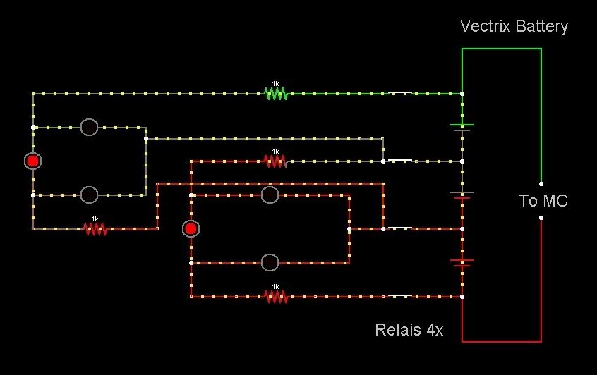
The code for the http://www.falstad.com/circuit/ is:
$ 1 5.0E-6 0.02528395958047465 58 5.0 50
v 768 240 768 144 0 0 40.0 37.0 0.0 0.0 0.5
v 768 336 768 240 0 0 40.0 37.0 0.0 0.0 0.5
v 768 432 768 336 0 0 40.0 37.0 0.0 0.0 0.5
w 768 144 768 80 0
w 768 432 768 496 0
x 849 305 919 311 0 24 To MC
w 768 144 704 144 0
s 656 336 704 336 0 0 false
s 656 240 704 240 0 0 false
s 656 144 704 144 0 0 false
w 768 240 704 240 0
w 768 336 704 336 0
s 656 432 704 432 0 0 false
w 768 432 704 432 0
w 768 80 880 80 0
w 880 80 880 272 0
w 768 496 880 496 0
w 880 496 880 320 0
x 766 57 920 63 0 24 Vectrix Battery
x 645 488 742 494 0 24 Relais 4x
w 560 432 656 432 0
w 560 240 656 240 0
w 560 144 656 144 0
r 448 432 560 432 0 1000.0
r 560 240 448 240 0 1000.0
w 448 432 384 432 0
w 448 240 384 240 0
w 608 336 656 336 0
w 608 336 608 288 0
w 608 336 608 384 0
162 608 384 384 384 1 1.4 1.0 0.0 0.0
162 384 288 384 384 1 2.4 1.0 0.0 0.0
162 384 288 608 288 1 1.4 1.0 0.0 0.0
w 384 240 384 288 0
w 384 432 384 384 0
w 640 272 336 272 0
w 624 208 336 208 0
r 560 144 448 144 0 1000.0
w 448 144 256 144 0
w 336 272 336 336 0
w 256 144 160 144 0
162 320 288 160 288 1 1.4 1.0 0.0 0.0
r 336 336 160 336 0 1000.0
w 624 208 656 208 0
w 656 208 656 240 0
w 640 272 656 272 0
w 656 272 656 336 0
162 160 192 160 288 1 2.4 1.0 0.0 0.0
w 160 144 160 192 0
w 160 288 160 336 0
w 320 208 320 192 0
w 336 208 320 208 0
w 320 208 320 288 0
162 160 192 320 192 1 1.4 1.0 0.0 0.0
o 0 64 0 35 80.0 0.05 0 -1
o 1 64 0 35 640.0 3.2 1 -1
o 16 64 0 35 80.0 0.1 2 -1
o 53 64 0 35 5.0 0.1 3 -1
This information may be used entirely at your own risk.
There is always a way if there is no other way!
Hi Mik,
my first reaktion was something like "what the hell..." I opened the links after that and had a big surprise: If yo compare the
two originalcircuits you see they are nearly identical in form and funktion. "Only" difference the one uses transistros to drive
the LEDs , the other uses only LEDs driving themselve. Both circuits have the problem that they are designed to work with only
two battery parts. As I did some testing with the transistor-type, there is a little problem with switching the relais: if they
don´t switch exactly at the same time the circuit reacts and draws much more curent destroying the LEDs, so the next step will be
a constant-curent subcircuit for each LED (with a transistor or a FET (Feldeffekttransistor)).constant curent circuits (german)
Greetings Mike
Pages