Hysteresis is just a bad way to create torque because it's existence signifies heat creation.
What might work better is something closer to a normal motor, but simplified and specialized for the desired task.
The idea might go like this...
You use a high efficiency higher rpm RC motor as your base. You then connect that motor to a planetary gear as before. Now you surround the planetary gear with a disk, but this time you insert alternating north and south high powered Neodymium magnets.
Now you have the basis for a motor / generator.
Here's were you go off the deep end...
Connect two coils spaced on different parts of the magnet disk so that they CANCEL each other out. This is like shorting the circuit and current will be unable to flow.
In the "cancelling" situation the positive side reacts against the negative and creates an opposing force on the disk. This is like having no "slip" or direct drive.
The other extreme is when you "open" the circuit and now you will have some slight cogging, but this should be small. "Slip" will be nearly 100% with only a slight cogging. This is the "freewheeling" condition.
To control this you need a circuit and MOSFETS. (a lot to invent)
The advantage of this is that you now are dealing with magnetic flux and copper losses rather than "waste products" (hysteresis) and if you can create a kind of "standing wave" between the opposing coils then the current will be low and that means heat will be low.
It's worth thinking about...
(D-Drive is still better)
The purpose of all this is to allow one motor to achieve higher efficiency and run in it's optimal rpm range at all times and then devise a variable speed geardown to get that power to the rear wheel with the least amount of losses. We know that bigger motors tend to be better motors, but we are trying to skimp on the weight and use unusual solutions to get where we want to go.
Your basic run of the mill mid drive motor system is excellent as it is, so improving on that will be difficult. Using plain old multispeed gearing and a mid drive is hard to beat.
.
I probably should have started this thread with a review of what a typical ebike already does.
If you begin to accelerate from a standing start with a full throttle (who doesn't?) and you are on a road with a very slight uphill grade of 1%, then the chart above shows how 1000 watts of input gets "lost in the system" with a direct drive.
Until you get above half of your maximum speed your heat related copper losses (red) completely dominates over everything else.
With a mid drive motor this chart will not apply. The advantage of multispeed gearing is that a smaller motor can run near it's optimal speed and that means most of the 1000 watts going in goes to forward motion rather than heat.
So in a sense the "problem" is most easily solved with multispeed gearing.
(my first ebike in 2006 had multispeed gearing... and it did the job)
---------------
Another point is that both "Wind Loss" and "Hill Loss" increase with speed.
So having the ability to lower your gearing really helps. In the old days people used to swear by these big hub motors (25 lbs+) and the thinking was that you attack the heat problem with brute force, but you never escape the fact that higher speeds still mean higher losses.
It takes less power to go slowly up a hill.
---------------
Based on "where things are going" in the industry and given the way the laws are about power (250 watts Europe, 750 watts US) the mid drive motor blended with the pre-existing multispeed gearing is most probably the endpoint of this quest.
Finally got my old PC operational again, so I'm going back over some of the ideas and using FEMM to validate their potential.
It actually wasn't until I started looking at the solenoid as a concept with FEMM that I realized that the typical solenoid really only works in one direction. I also discovered that "long travel" in a solenoid is a bad idea because the air gap gets too big.
My thinking is that in one of the bicycles frame tubes you would insert a "Push Pull Solenoid" that would directly connect to the bottom bracket through a crank much like in a gas engine.
The Gruber Assist does the same kind of thing, but uses multiple gear reduction techniques.
The idea of the solenoid is to reduce the motor to something with very few moving parts.
Still not convinced it's a great idea... but it's an idea...
The biggest question mark is friction:
"Is a solenoid going to have less friction than a bunch of gears?"
(actually it might)
------------------
This doesn't require magnets after all (doesn't really help) so other than friction the solenoid motor could be directly attached to the bottom brackets spindle and you could pedal when no electrical power was active. The reverse would not be true, namely if the solenoid is working you aren't going to be able to not pedal.
----------------
The biggest advantage of using a solenoid is that it should last indefinitely. Since all the parts are "large" to handle the high loads involved (short stroke) you are not going to see small little gears let go after a few hundred miles. In theory I could imagine 10,000 miles without any troubles and actually at that point everything should be smoothed out and working nicely. Sort of like breaking in a new gas motor... the first 1,000 miles is just to get it loosened up.
.
Hmmmm... should have studied up on "Push Pull Solenoids".
This puts the permanent magnet back in again. I'm going to have to do another FEMM simulation on this technique.
Update:
Magnets reintroduce cogging. That's bad news... it's actually better to keep the permanent magnets out of this because cogging would make the solenoid idea really bad if the power failed or if you just want to pedal without using the motor.
Okay... we start with what a single coil looks like in FEMM:
.
.
We study the magnetic flux across the gap:
.
.
Then we look at what M22 Steel (electrical steel) is capable of:
.
.
Now in FEMM we move the position of the disc component so that we can see how flux linkage effects the maximum Force (in Newtons) that can be attained:
.
.
Now we do some simple math to convert everything and we come to see what is the maximum power output for a Switched Reluctance Disc Motor(s):
.
.
This assumes four coils in the front disc and four coils in the rear for a total of eight (8) coils.
As you can see it takes some rpm to generate any power.
For the American audience for ebikes this seems "underpowered", but it could work in Europe and Australia because of their 250 watt limits.
To increase power you need more coils... I could imagine 8 coils per disc as being possible. Even with a total of 16 coils you are still only producing a maximum of 1400 watts at 40 mph which for a lot of Americans will seem boring.
Small motors that use geardowns have the advantage of higher rpm. A disc based motor is like a hub motor in that it spins at the same speed as the rear wheel and so it's low rpm power is limited by:
Power = Torque * Rpm
...and switched reluctance motors have a definite maximum torque potential based on the electrical steel being used.
The best feature of this system would be that you could simply bolt it on in place of your existing disc brakes. Efficiency with switched reluctance motors can be exceptionally high, so that's a plus. The biggest negative is that you cannot "burn rubber" with this sort of motor because while the power is clean, efficient, lightweight and without cogging, it's not super strong.
Legal issues would be reduced because it's essentially impossible to exceed the designed power limits.
.
This is an idea I've been toying with for about five years but until now there was a technical problem that I couldn't seem to get past.
The idea is to "insert" thin pieces of iron into a carbon fiber rim so that you create alternating regions of either high magnetic potential or low. What had made me "stuck" in the past is that the technical problem of building it was beyond anything I could accomplish.
I had thought of the idea of using some kind of specially woven carbon fiber cloth that alternated with carbon and iron. Seems too tricky.
Another idea was to insert iron plates, but how might you assemble that so that the rim didn't fall apart under stress? Again, too unworkable.
Finally I came up with a new idea...
.
.
When two magnets are placed outside a contained area iron filings will accumulate in the areas of highest magnetic field strength:
.
.
.
.
So the idea would be to MIX iron filings into the RESIN as you build up a carbon fiber rim and then before the resin can set up you apply powerful magnets which draw the iron filings into alignment. Once the resin sets these iron filings create alternating regions of high and low magnetic flux potential.
This solves the problem because you can build a solid carbon fiber rim very quickly. This is the sort of technique that could be done in mass production at a low cost. The iron filings can be electrical silicon steel or some of these more high tech materials being used in transformer cores.
One thing to consider is an alternating current in those magnets because that should "shake" the iron filings and improve migration through the cloth. Ideally you want all the iron filings to accumulate in the desired regions.
Finally, you now have the basis for a switched reluctance motor because the rim will have alternating regions of high and low magnetic flux potential.
This will give torque that is roughly three times a disc motor.
Finally got my old PC operational again, so I'm going back over some of the ideas and using FEMM to validate their potential.
It actually wasn't until I started looking at the solenoid as a concept with FEMM that I realized that the typical solenoid really only works in one direction. I also discovered that "long travel" in a solenoid is a bad idea because the air gap gets too big.
I may be able to supply you with a yoke and armature design that can deal with considerable airgaps and thus allow more useful travel. It is used in electric EGR-Valves for strokes of up to about 6mm with a rather linear force over stroke, but could easily be scaled for more stroke and higher force. Just send me a PM if interested.
The most important thing, which you should also be able assess with your FEMM software, is that apart from the airgap parts the rest of the magnetic circuit should be of the same cross section, all around the magnetic circuit. This will eliminate the flux density concentration in the moving armature and let you utilize the material in the most ideal way, thus also giving you the highest possible force.
My rides:
2017 Zero S ZF6.5 11kW, erider Thunder 5kW
It's a major problem with the concept of using a simple solenoid.
I have toyed in FEMM with a weird kind of "linear motor solenoid" that had a sort of track like the trains use and that might be a direction to look into. It was more along the switched reluctance direction, but permanent magnets could work too.
.
.
...a longer stroke is needed.
.
.
...still fiddling with the idea.
What if you suspened the "device" so as to have no friction? (floating piston)
I started by looking at how Halbach Arrays can levitate a train by orienting the magnets so that they face the coils. Then I took the Halbach Array and rotated it around into the shape of a cylinder. I've seen Halbach Spheres, but never a Halbach Cylinder.
In the case of a Solenoid we really don't need multiple wavelengths, so I reduced the Halbach Cylinder to just a single wavelength and then placed a coil in the middle.
What happens?
Current in one direction creates a Force in one direction.
Reverse the current and the Force reverses.
The Force is in the shape of a normal sine curve.
----------------
The stroke is as long as you want it to be based on the magnets you use. You can use very powerful Neodymium magnets and create a very powerful field. I was generating significant Forces with just coils, so it does not appear to require iron and that means there is no cogging.
I'm very impressed with it... will have to play with it some more...
I have been watching this page and have a few thoughts . 1. some out runner motors don't use steel at all they are just a set of stator input coils that are energized by the controller and a set of copper or aluminum coils that are a closed loop armature . The back EMS generated in the armature coils by the input coils is what drives the armature forward or reverse copper or aluminum have been used. 2. If the "armature" of the solenoid was made of carbon fiber and the aluminum coils, the reduction in weight would make it easer to float [no contact friction]. these small R/C brushless can generate a lot of torque with high efficiency and very low weight instead of rotational you could build it linear push/pull like a steam engine . 3. if you could build the armature into the rim sort of a double rim than, if the outer rim is a floating armature and the axle and inner rim would be a stationary stator . just a few thoughts LaTeR
I have been watching this page and have a few thoughts . 1. some out runner motors don't use steel at all they are just a set of stator input coils that are energized by the controller and a set of copper or aluminum coils that are a closed loop armature . The back EMS generated in the armature coils by the input coils is what drives the armature forward or reverse copper or aluminum have been used. 2. If the "armature" of the solenoid was made of carbon fiber and the aluminum coils, the reduction in weight would make it easer to float [no contact friction]. these small R/C brushless can generate a lot of torque with high efficiency and very low weight instead of rotational you could build it linear push/pull like a steam engine . 3. if you could build the armature into the rim sort of a double rim than, if the outer rim is a floating armature and the axle and inner rim would be a stationary stator . just a few thoughts LaTeR
I have been watching this page and have a few thoughts . 1. some out runner motors don't use steel at all they are just a set of stator input coils that are energized by the controller and a set of copper or aluminum coils that are a closed loop armature . The back EMS generated in the armature coils by the input coils is what drives the armature forward or reverse copper or aluminum have been used. 2. If the "armature" of the solenoid was made of carbon fiber and the aluminum coils, the reduction in weight would make it easer to float [no contact friction]. these small R/C brushless can generate a lot of torque with high efficiency and very low weight instead of rotational you could build it linear push/pull like a steam engine . 3. if you could build the armature into the rim sort of a double rim than, if the outer rim is a floating armature and the axle and inner rim would be a stationary stator . just a few thoughts LaTeR
Wow, triple posted. Hope one of the moderators can clean that up. This forum is really slow with the first post attempt, but then it's not too bad.
Anyway, yes, I know they use aluminum in place of copper sometimes because the resistance is similiar, but aluminum is lighter. (resistance 1.68×10⁻⁸ copper vs 2.82×10⁻⁸ aluminum)
Carbon fiber is interesting because it's NOT magnetic. So, yeah, there are a lot of ways to put this stuff together. I've been learning and playing with this stuff for years and it still surprises me.
The (high rpm motor) mid drive solution for ebikes seems very dominant right now, and it's a great solution, but it's hard to imagine it ever being very reliable.
Still fun to ponder other ideas...
Note: We live in a very visual age so I'd encourage posting with any and every image you can to get your point across. It's hard to grasp another persons ideas without an image. (even a crude one)
Paint in Windows works fine. Then I convert to jpg so that you can upload. I go back and forth between Windows and an Android tablet which also does image manipulations. (free apps)
.
If you were to place a coil between two magnets of opposing polarity you will be able to push or pull depending on the direction of current in the coil.
This really just increases the field in the middle and smoothes everything out.
Note that in the very center there is no field at all.
Where traditional solenoids fail is that they offer limited piston stroke.
The image above represents just one half of a cross section of the Halbach Solenoid. By using very powerful magnets in a Halbach configuration we are able to create very powerful flux well inside the cylinder where coils will exist. 0.4 Teslas is impressive for essentially "air".
The red represents the areas closest to the outer rim of the cylinder and this is where the coils will generate their maximum force. As you move inward towards the center of the cylinder the flux is lower. This is okay because in the center we would have the pushrod anyway, so the less effective space goes to good use.
.
Sometimes knowing that you "do not yet know" is the best feeling you can have. :)
I was looking at the Halbach Solenoid and saw that it might be possible to further increase the magnetic flux if I did a little redesign. It worked and strength was increased.
Now I suspect there will be quite a few further iterations to see where it can get better.
Halbach Spheres have been able to produce mind boggling magnetic flux, so I'm going to check this out. Back to the drawing board as they say.
The cylinders are thought of as extending infinitely.
In this form the cylinders are useful for "rotary" motion, but I'm fiddling with the idea of having no gearing and driving directly through a crank with a "solenoid-like" behavior. I might switch names here because I'm drifting away from a "true solenoid".
It appears that cylinder "k=3" has the flux pattern I want, but it has to be elongated to extend the stroke because I need it to work perpendicular to it's normal function, so the final result might not resemble the original idea.
.
Coils need to "loop" and in a magnetic field that's going to mean that at some point the force will be positive and at another negative. You can get around that if you go axial and have an inside and an outside, but building something like that is difficult. Magnets tend to be sold as blocks and not exotic and graceful radial magnetic items. So just as a practical matter it's probably better to be thinking in standard blocks.
.
.
So in this example we use standard blocks and "stay square" in that the coil will go into the image on one side and out on the other and in between the coils would snake sideways between. The copper in between gets wasted, but the magnetic force is so high because of the square blocks that the net result is good. It's also open to the air so it would have good cooling.
135 watts produces 142 newtons of Force which is good. Any time you get a newton from a watt you are doing well.
Stretching the wavelength will increase the stroke of this device. Will continue to see how far it can be stretched.
It uses "square" (rectangular) magnets, but manages to function in a radial way because of carefully shaped silicon steel.
What's interesting is that the coils move, but the magnets and silicon steel do not and actually since the field never changes there is no hysteresis in the iron. One might even use a material without laminations.
Very long piston stroke and you can configure the field strength by how you shape things.
100% of the copper is used (no wasted end turns) so it has the potential to be efficient.
.
The coil and rail gun concepts are interesting because there is no real limit to their stroke.
.
.
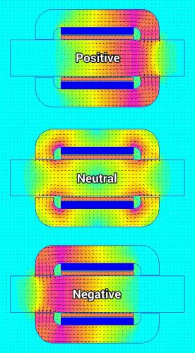
I sort of stumbled upon this idea. The dark blue color areas are the magnets which both point outward from the center. The copper color areas are the coils.
What (unbelievably) seems to happen is the magnets create a circulation of magnetic flux that flows through the core. (neutral) When the coils are activated (either positive or negative) a force is generated because coils within a pre-existing magnetic field create a force. (left hand rule) There is no real limit to the stroke and if the outer structure is held "fixed" then the only thing that moves is the core. (shaft) It's design has the shape of a cylinder, so efficiency is good.
.
.
Frankly it seems "impossible"... so I'm going to have to make sure it's real. Would be nice to see an existing system using similiar principles.
With a bicycle we have a bottom bracket and a downtube that connects to the headset. This is the main "stressed member" of a bicycle, so it makes sense that if you electrify a bicycle that you might try to incorporate the motor as part of the structural strength of the frame.
So in the diagram we are looking inside the main downtube of the bicycle. A magnet creates a circulating flux between a sliding portion inside and the stationary tube outside. Ball bearings could be incorporated into the sliding "plug" to reduce friction. You could use multiple "plugs" which will increase power or you can increase the tube diameter for more power or both. Copper is efficiently used as 100% is part of power production (coil shaped) with no end turns.
It can be made to be "stealthy" because the motor is inside the downtube and the crank-crankarm can be hidden inside the bottom bracket.
.
I might just be doing unneccessary work here though...
The Coil Gun works on the simple principle that a coil will attract metal when it's magnetic field is "rising".
If you simply put a "piston" made of magnetic material inside a coil you can at least get power on each end of the stroke. It would mean that there would be blank areas without power (sort of like switched reluctance) but the simplicity and lack of magnets might justify the idea.
So what I realized is the Coil Gun is essentially a Switched Reluctance motor except rather than being in just one dimension it's shaped into a radial coil.
This means that this will ONLY work when the plug is being "attracted" to the coil. It's exactly the same as a Switched Reluctance motor because if you overshoot with your coil currents you will end up subtracting from the power output. This means that while this is a more simplified mechanical design the control logic will require some greater sophistication.
The only real difference between this and the standard solenoid is this has no "end" on one side. The standard solenoid smacks into an "end" when it closes. Do I really need so much freedom? Hmmmm... not sure... a piston stroke tends to have clearly defined "ends".
When you know where the "end" is going to be you can time it more easily.
.
One big criteria for any design is that it's light weight.
Silicon Steel is very heavy stuff, but if you want to increase magnetic flux in most designs you need to keep adding more and more of the stuff to improve performance. This is why all the "old school" designs used heavy motors because long ago they realized that more Silicon Steel is better. (also, Neodymium magnets didn't exist back then)
We can't do that. (Joke: "Or you end up with a 25 lb hub motor")
Neodymium magnets are great because they create a lot of magnetic flux, but unless you are doing a true Halbach Array axial flux (rotating) design you are going to be dealing with Silicon Steel and laminations.
For something that behaves like a solenoid we want maximum force for a limited weight and we also want high efficiency which means lot's of copper. (however that's heavy stuff too)
The image above is something I thought of today.
What if you created a circle of nothing but magnets?
Between the magnets you would place your copper and in the image above the current would either flow from outside the circle in or from inside out. Thinking in 3-d we would expect the Force generated to be either coming out of the image or going in.
.
.
Here's the only problem...
Currents will flow in one direction (in or out) but have no return route. The way to solve this would be to have two circular magnet arrays which "spin" in opposite directions. A coil goes "inward" in one circle and "outward" in it's parallel circle. You will lose a percentage of your copper to end turns, but since the volume of copper is large efficiency will still be good. I'd rather be adding more copper than Silicon Steel.
Some relationship will exist between the length of "stroke" and the amount (%) of end turns.
You could potentially just use one magnet circle and just loop back outside of it. The copper outside the circle is not doing anything useful, but this design seems capable of using a lot of copper in those spaces and so if you can increase copper fill by a factor of (say) 6x and you have to pay a 50% end turn penalty it still might be pretty good.
Another possibility is to "straddle" the magnets with the coils while using one circular magnet set. Each half of the coils will be within the magnetic field half of the time. The current is always in the same direction... a little like pedaling... one pedal "pushes" and then there is a dead spot until the other side "pushes". In 3-d space if you look at a person riding in front of you and you are to his left, then the pedals turn counter-clockwise. If that rider turns the other way he appears to be pedaling clockwise.
This idea appears to have been correct. By bending the magnetic flux to go in two ways it guarantees that a solenoid can find "something" to generate a force with. There is a patent with the same basic idea:
.
.
This other idea is likely incorrect:
.
.
In FEMM the coils suggest they are generating a large Force, but the effect doesn't seem to make it beyond the coils. My best guess is that FEMM is giving me misleading information because you can have a Force that doesn't "push" anything. It would be like a 100 hp motor that is put in neutral... you are just spinning the motor and not doing any real work. FEMM doesn't allow a measurement on anything that is attached to anything else, so in "free space" it gives results that might be an illusion.
At this stage I'm assuming it's incorrect.
...it actually seems to behave like an Eddy Current clutch.
.
Okay... this is looking like an actual workable idea.
Let me review what the issues are that drive us toward alternative solutions to existing mid drives:
1) Small motors running at high rpm are efficient, but high rpm causes problems with gearing.
2) Gearing is heavy.
3) Gearing is noisy.
4) Gearing introduces friction.
5) Gearing can have reliability problems.
---------------------------
The idea is to be able to contain an electric "motive device" concealed within the downtube of a bicycle in such a way that it's construction acts as a "stressed member" for the frame.
In the image above I use ordinary square magnets (much less expensive) and have found through FEMM that magnetic field strength is good.
One might construct this by assembling each of the six magnet "units" individually and glue it all together with carbon fiber. Carbon fiber is entirely non-magnetic so it will not interfere with the magnets. You then couple these all together into a single carbon fiber tube which will become the downtube of the bicycle.
No Silicon Steel.
Copper coils will become the "active" part of the "motive device" and they will slide in and out of the tube in a piston (solenoid) like manner. The sliding coils will be connected to the crank (bottom bracket) so as to cause the pedals to have additional power. Since there is no cogging (no silicon steel) a rider can pedal without power. However, this "motive device" will not allow someone to get electric power without pedaling along. (so it's a true pedelec)
.
Brushed ???
At a maximum pedal rpm of 100 rpm you don't have to worry about brushes "floating" because of excessive speed, so you don't need much in the way of spring tension. I know it's fashionable to choke at the idea of brushes as too "old school" (and they are) but for a DIY builder who might want to experiment with this idea it gets the job done and you have no complicated hall sensors to fiddle around with. An actual retail product would go brushless.
.
.
The bicycle spindle (inside the bottom bracket) would be a crankshaft. The counterweight needs to be just enough to balance the weight of the copper coils which should be no more than a pound or two. (kg). An aluminum crank arm would be lightweight.
.
These magnets are running about $3 - $4 each right now.
The next step will be to actually run the numbers to see how well it would function.
.
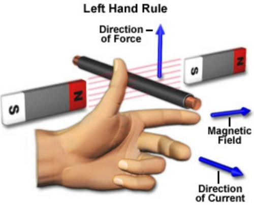
Let's go back to the basics... the Left Hand Rule:
.
.
Unless I'm totally missing something whenever there is a magnetic field pointing in one direction, then a current flowing perpedicular to that magnetic field will create a force along yet another vector. In this case the force vector will act as a torque about the center.
The center is the spindle inside the bottom bracket and it will attach to the circular magnet.
The coils will be created in two sets and less than 50% of the copper is used for power.
-------------------
So what do you end up with?
No AC, just DC
This is the most bizarre thing about this idea. If a force is created continuously about a radius from a constant current then the magnet should spin which will drive the spindle and the pedals.
No brushes.
No hall sensors.
...actually there are no moving parts at all.
No gears or crankarm.
No friction.
No noise.
It's so strange that I'm unwilling to completely believe it !!!
Maybe a circular implementation cancels itself out somehow?
Hmmmmmmmmmmm...
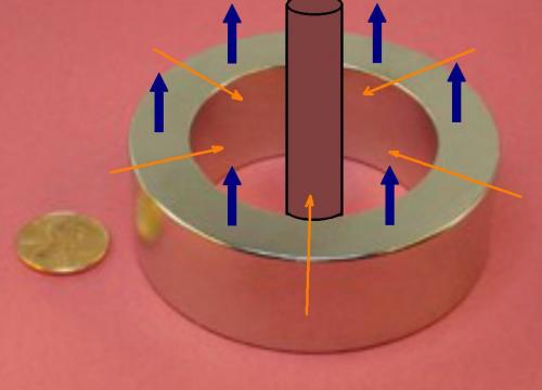
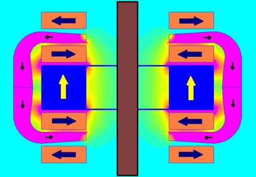
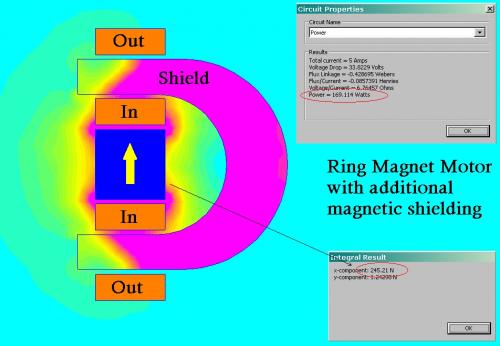
Note: The copper will circle back BEHIND the silicon steel shells (2) and those shells will have holes in them to allow copper to be snaked through. The shells are not solid. These shells act as "magnetic shielding" which is neccessary because without it this magnet is dangerous.
A possible problem is that this much magnet might be simply too dangerous for public use in a bike shop or by an untrained individual. It's a scary magnet for just a pound of material. However, if the entire unit were sold so that you just bolt it on (never opening it) then it could be okay. My guess is that curious folks will eventually get inside and then hurt themselves, but as long as there is a warning label it should be legal.
.
.
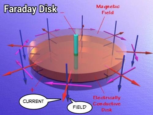
The vectors are identical to a Faraday Disk. The Faraday Disk was the original motor, but it's not very efficient or powerful. One wonders if the use of an insanely strong Neodymium magnet is enough to make the idea workable. Homopolar motors do exist.
.
It's looking good in FEMM. The magnet clearly generates a force and it all seems pointing correctly. FEMM is a 2-d software program and to really do this right you need 3-d, but in the abstract the concept seems okay.
.
.
Copper usage is TERRIBLE with this concept because most of it gets spent looping around back behind the active part of the motor. By adding silicon steel you create a mechanism for magnetic flux to loop around and it also "shields" the wasted copper. It's really bizarre to actively be trying to CANCEL the effects of portions of the copper. Electrical efficiency can be increased with more and more copper, but you are adding weight along the way.
It still looks very promising.
.
.
To test this you might buy an inexpensive ring magnet and just put a little something in the middle to allow it to spin freely. You then just get a 1.2 volt AA battery and run some current through a wire as it rides over the spinning ring. If it works, then you know it's "real".
This is really interesting because if it can be done efficiently on an ebike it really reduces the number of moving parts and complexity.
Could this be "it"?
Not sure yet... more likely useful for 100 watt assistance than overwhelming power, but it's in the area of low power that attention needs to be focused. I ride a regular bike 2 hours a day and only produce about 100 watts most of the time, but it gets me everywhere.
It's all going to come down to efficiency... either it's efficient or it's not.

.
Hysteresis is just a bad way to create torque because it's existence signifies heat creation.
What might work better is something closer to a normal motor, but simplified and specialized for the desired task.
The idea might go like this...
You use a high efficiency higher rpm RC motor as your base. You then connect that motor to a planetary gear as before. Now you surround the planetary gear with a disk, but this time you insert alternating north and south high powered Neodymium magnets.
Now you have the basis for a motor / generator.
Here's were you go off the deep end...
Connect two coils spaced on different parts of the magnet disk so that they CANCEL each other out. This is like shorting the circuit and current will be unable to flow.
In the "cancelling" situation the positive side reacts against the negative and creates an opposing force on the disk. This is like having no "slip" or direct drive.
The other extreme is when you "open" the circuit and now you will have some slight cogging, but this should be small. "Slip" will be nearly 100% with only a slight cogging. This is the "freewheeling" condition.
To control this you need a circuit and MOSFETS. (a lot to invent)
The advantage of this is that you now are dealing with magnetic flux and copper losses rather than "waste products" (hysteresis) and if you can create a kind of "standing wave" between the opposing coils then the current will be low and that means heat will be low.
It's worth thinking about...
(D-Drive is still better)
The purpose of all this is to allow one motor to achieve higher efficiency and run in it's optimal rpm range at all times and then devise a variable speed geardown to get that power to the rear wheel with the least amount of losses. We know that bigger motors tend to be better motors, but we are trying to skimp on the weight and use unusual solutions to get where we want to go.
Your basic run of the mill mid drive motor system is excellent as it is, so improving on that will be difficult. Using plain old multispeed gearing and a mid drive is hard to beat.
.
I probably should have started this thread with a review of what a typical ebike already does.
If you begin to accelerate from a standing start with a full throttle (who doesn't?) and you are on a road with a very slight uphill grade of 1%, then the chart above shows how 1000 watts of input gets "lost in the system" with a direct drive.
Until you get above half of your maximum speed your heat related copper losses (red) completely dominates over everything else.
With a mid drive motor this chart will not apply. The advantage of multispeed gearing is that a smaller motor can run near it's optimal speed and that means most of the 1000 watts going in goes to forward motion rather than heat.
So in a sense the "problem" is most easily solved with multispeed gearing.
(my first ebike in 2006 had multispeed gearing... and it did the job)
---------------
Another point is that both "Wind Loss" and "Hill Loss" increase with speed.
So having the ability to lower your gearing really helps. In the old days people used to swear by these big hub motors (25 lbs+) and the thinking was that you attack the heat problem with brute force, but you never escape the fact that higher speeds still mean higher losses.
It takes less power to go slowly up a hill.
---------------
Based on "where things are going" in the industry and given the way the laws are about power (250 watts Europe, 750 watts US) the mid drive motor blended with the pre-existing multispeed gearing is most probably the endpoint of this quest.
But it's still fun to ponder other ideas...
.
Finally got my old PC operational again, so I'm going back over some of the ideas and using FEMM to validate their potential.
It actually wasn't until I started looking at the solenoid as a concept with FEMM that I realized that the typical solenoid really only works in one direction. I also discovered that "long travel" in a solenoid is a bad idea because the air gap gets too big.
My thinking is that in one of the bicycles frame tubes you would insert a "Push Pull Solenoid" that would directly connect to the bottom bracket through a crank much like in a gas engine.
The Gruber Assist does the same kind of thing, but uses multiple gear reduction techniques.
The idea of the solenoid is to reduce the motor to something with very few moving parts.
Still not convinced it's a great idea... but it's an idea...
The biggest question mark is friction:
"Is a solenoid going to have less friction than a bunch of gears?"
(actually it might)
------------------
This doesn't require magnets after all (doesn't really help) so other than friction the solenoid motor could be directly attached to the bottom brackets spindle and you could pedal when no electrical power was active. The reverse would not be true, namely if the solenoid is working you aren't going to be able to not pedal.
----------------
The biggest advantage of using a solenoid is that it should last indefinitely. Since all the parts are "large" to handle the high loads involved (short stroke) you are not going to see small little gears let go after a few hundred miles. In theory I could imagine 10,000 miles without any troubles and actually at that point everything should be smoothed out and working nicely. Sort of like breaking in a new gas motor... the first 1,000 miles is just to get it loosened up.
.
Hmmmm... should have studied up on "Push Pull Solenoids".
This puts the permanent magnet back in again. I'm going to have to do another FEMM simulation on this technique.
Update:
Magnets reintroduce cogging. That's bad news... it's actually better to keep the permanent magnets out of this because cogging would make the solenoid idea really bad if the power failed or if you just want to pedal without using the motor.
So I'm thinking magnets are a bad idea for this.
.
Switched Reluctance Disc Motor FEMM Analysis
.
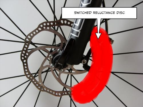
.
Okay... we start with what a single coil looks like in FEMM:

.
.
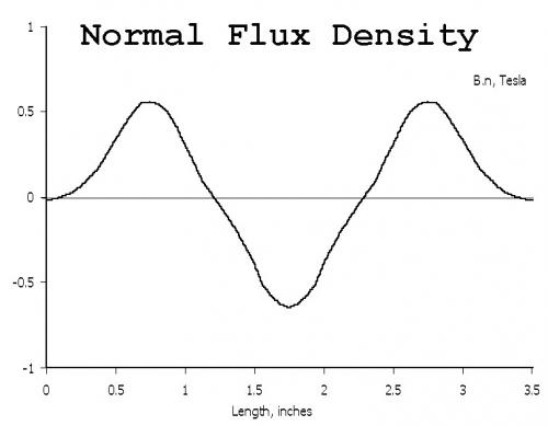
We study the magnetic flux across the gap:
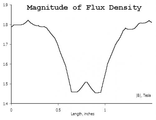
.
.
Then we look at what M22 Steel (electrical steel) is capable of:
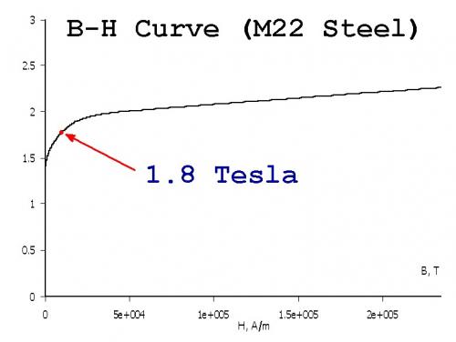
.
.
Now in FEMM we move the position of the disc component so that we can see how flux linkage effects the maximum Force (in Newtons) that can be attained:
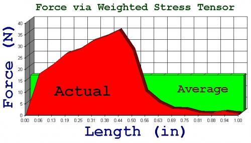
.
.
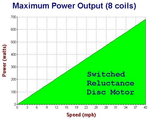
Now we do some simple math to convert everything and we come to see what is the maximum power output for a Switched Reluctance Disc Motor(s):
.
.
This assumes four coils in the front disc and four coils in the rear for a total of eight (8) coils.
As you can see it takes some rpm to generate any power.
For the American audience for ebikes this seems "underpowered", but it could work in Europe and Australia because of their 250 watt limits.
To increase power you need more coils... I could imagine 8 coils per disc as being possible. Even with a total of 16 coils you are still only producing a maximum of 1400 watts at 40 mph which for a lot of Americans will seem boring.
Small motors that use geardowns have the advantage of higher rpm. A disc based motor is like a hub motor in that it spins at the same speed as the rear wheel and so it's low rpm power is limited by:
Power = Torque * Rpm
...and switched reluctance motors have a definite maximum torque potential based on the electrical steel being used.
The best feature of this system would be that you could simply bolt it on in place of your existing disc brakes. Efficiency with switched reluctance motors can be exceptionally high, so that's a plus. The biggest negative is that you cannot "burn rubber" with this sort of motor because while the power is clean, efficient, lightweight and without cogging, it's not super strong.
Legal issues would be reduced because it's essentially impossible to exceed the designed power limits.
.
.
Carbon Fiber Switched Reluctance Rim Motor
.
This is an idea I've been toying with for about five years but until now there was a technical problem that I couldn't seem to get past.
The idea is to "insert" thin pieces of iron into a carbon fiber rim so that you create alternating regions of either high magnetic potential or low. What had made me "stuck" in the past is that the technical problem of building it was beyond anything I could accomplish.
I had thought of the idea of using some kind of specially woven carbon fiber cloth that alternated with carbon and iron. Seems too tricky.
Another idea was to insert iron plates, but how might you assemble that so that the rim didn't fall apart under stress? Again, too unworkable.
Finally I came up with a new idea...
.
.
When two magnets are placed outside a contained area iron filings will accumulate in the areas of highest magnetic field strength:
.
.
.
.
So the idea would be to MIX iron filings into the RESIN as you build up a carbon fiber rim and then before the resin can set up you apply powerful magnets which draw the iron filings into alignment. Once the resin sets these iron filings create alternating regions of high and low magnetic flux potential.
This solves the problem because you can build a solid carbon fiber rim very quickly. This is the sort of technique that could be done in mass production at a low cost. The iron filings can be electrical silicon steel or some of these more high tech materials being used in transformer cores.
One thing to consider is an alternating current in those magnets because that should "shake" the iron filings and improve migration through the cloth. Ideally you want all the iron filings to accumulate in the desired regions.
Finally, you now have the basis for a switched reluctance motor because the rim will have alternating regions of high and low magnetic flux potential.
This will give torque that is roughly three times a disc motor.
Torque = Force * Radius
.
I may be able to supply you with a yoke and armature design that can deal with considerable airgaps and thus allow more useful travel. It is used in electric EGR-Valves for strokes of up to about 6mm with a rather linear force over stroke, but could easily be scaled for more stroke and higher force. Just send me a PM if interested.
The most important thing, which you should also be able assess with your FEMM software, is that apart from the airgap parts the rest of the magnetic circuit should be of the same cross section, all around the magnetic circuit. This will eliminate the flux density concentration in the moving armature and let you utilize the material in the most ideal way, thus also giving you the highest possible force.
My rides:
2017 Zero S ZF6.5 11kW, erider Thunder 5kW
6mm is the limited kind of stroke I've found too.
It's a major problem with the concept of using a simple solenoid.
I have toyed in FEMM with a weird kind of "linear motor solenoid" that had a sort of track like the trains use and that might be a direction to look into. It was more along the switched reluctance direction, but permanent magnets could work too.
.
.
...a longer stroke is needed.
.
.
...still fiddling with the idea.
What if you suspened the "device" so as to have no friction? (floating piston)
A tube filled with a cylindrical Halbach array?
.
Halbach Solenoid ?
.
.
This is very interesting.
I started by looking at how Halbach Arrays can levitate a train by orienting the magnets so that they face the coils. Then I took the Halbach Array and rotated it around into the shape of a cylinder. I've seen Halbach Spheres, but never a Halbach Cylinder.
In the case of a Solenoid we really don't need multiple wavelengths, so I reduced the Halbach Cylinder to just a single wavelength and then placed a coil in the middle.
What happens?
Current in one direction creates a Force in one direction.
Reverse the current and the Force reverses.
The Force is in the shape of a normal sine curve.
----------------
The stroke is as long as you want it to be based on the magnets you use. You can use very powerful Neodymium magnets and create a very powerful field. I was generating significant Forces with just coils, so it does not appear to require iron and that means there is no cogging.
I'm very impressed with it... will have to play with it some more...
.
I have been watching this page and have a few thoughts . 1. some out runner motors don't use steel at all they are just a set of stator input coils that are energized by the controller and a set of copper or aluminum coils that are a closed loop armature . The back EMS generated in the armature coils by the input coils is what drives the armature forward or reverse copper or aluminum have been used. 2. If the "armature" of the solenoid was made of carbon fiber and the aluminum coils, the reduction in weight would make it easer to float [no contact friction]. these small R/C brushless can generate a lot of torque with high efficiency and very low weight instead of rotational you could build it linear push/pull like a steam engine . 3. if you could build the armature into the rim sort of a double rim than, if the outer rim is a floating armature and the axle and inner rim would be a stationary stator . just a few thoughts LaTeR
thank GOD I wake up above ground !!!!
Wow, triple posted. Hope one of the moderators can clean that up. This forum is really slow with the first post attempt, but then it's not too bad.
Anyway, yes, I know they use aluminum in place of copper sometimes because the resistance is similiar, but aluminum is lighter. (resistance 1.68×10⁻⁸ copper vs 2.82×10⁻⁸ aluminum)
Carbon fiber is interesting because it's NOT magnetic. So, yeah, there are a lot of ways to put this stuff together. I've been learning and playing with this stuff for years and it still surprises me.
The (high rpm motor) mid drive solution for ebikes seems very dominant right now, and it's a great solution, but it's hard to imagine it ever being very reliable.
Still fun to ponder other ideas...
Note: We live in a very visual age so I'd encourage posting with any and every image you can to get your point across. It's hard to grasp another persons ideas without an image. (even a crude one)
Paint in Windows works fine. Then I convert to jpg so that you can upload. I go back and forth between Windows and an Android tablet which also does image manipulations. (free apps)
.
Getting back to this Halbach Solenoid idea...
If you were to place a coil between two magnets of opposing polarity you will be able to push or pull depending on the direction of current in the coil.
This really just increases the field in the middle and smoothes everything out.
Note that in the very center there is no field at all.
.
.
.
.
.
.
Where traditional solenoids fail is that they offer limited piston stroke.
The image above represents just one half of a cross section of the Halbach Solenoid. By using very powerful magnets in a Halbach configuration we are able to create very powerful flux well inside the cylinder where coils will exist. 0.4 Teslas is impressive for essentially "air".
The red represents the areas closest to the outer rim of the cylinder and this is where the coils will generate their maximum force. As you move inward towards the center of the cylinder the flux is lower. This is okay because in the center we would have the pushrod anyway, so the less effective space goes to good use.
.
Sometimes knowing that you "do not yet know" is the best feeling you can have. :)
I was looking at the Halbach Solenoid and saw that it might be possible to further increase the magnetic flux if I did a little redesign. It worked and strength was increased.
Now I suspect there will be quite a few further iterations to see where it can get better.
Halbach Spheres have been able to produce mind boggling magnetic flux, so I'm going to check this out. Back to the drawing board as they say.
.
.
.

.
Halbach Cylinders as well as Halbach Spheres exist at wikipedia for reference:
http://en.m.wikipedia.org/wiki/Halbach_array
The cylinders are thought of as extending infinitely.
In this form the cylinders are useful for "rotary" motion, but I'm fiddling with the idea of having no gearing and driving directly through a crank with a "solenoid-like" behavior. I might switch names here because I'm drifting away from a "true solenoid".
It appears that cylinder "k=3" has the flux pattern I want, but it has to be elongated to extend the stroke because I need it to work perpendicular to it's normal function, so the final result might not resemble the original idea.
.
Going back to the basics...
Coils need to "loop" and in a magnetic field that's going to mean that at some point the force will be positive and at another negative. You can get around that if you go axial and have an inside and an outside, but building something like that is difficult. Magnets tend to be sold as blocks and not exotic and graceful radial magnetic items. So just as a practical matter it's probably better to be thinking in standard blocks.
.
.
So in this example we use standard blocks and "stay square" in that the coil will go into the image on one side and out on the other and in between the coils would snake sideways between. The copper in between gets wasted, but the magnetic force is so high because of the square blocks that the net result is good. It's also open to the air so it would have good cooling.
135 watts produces 142 newtons of Force which is good. Any time you get a newton from a watt you are doing well.
Stretching the wavelength will increase the stroke of this device. Will continue to see how far it can be stretched.
(still kind of wandering about)
.
This is sort of shaped like a shock absorber.
It uses "square" (rectangular) magnets, but manages to function in a radial way because of carefully shaped silicon steel.
What's interesting is that the coils move, but the magnets and silicon steel do not and actually since the field never changes there is no hysteresis in the iron. One might even use a material without laminations.
Very long piston stroke and you can configure the field strength by how you shape things.
100% of the copper is used (no wasted end turns) so it has the potential to be efficient.
.
.
The coil and rail gun concepts are interesting because there is no real limit to their stroke.
.
.
I sort of stumbled upon this idea. The dark blue color areas are the magnets which both point outward from the center. The copper color areas are the coils.
What (unbelievably) seems to happen is the magnets create a circulation of magnetic flux that flows through the core. (neutral) When the coils are activated (either positive or negative) a force is generated because coils within a pre-existing magnetic field create a force. (left hand rule) There is no real limit to the stroke and if the outer structure is held "fixed" then the only thing that moves is the core. (shaft) It's design has the shape of a cylinder, so efficiency is good.
.
.
Frankly it seems "impossible"... so I'm going to have to make sure it's real. Would be nice to see an existing system using similiar principles.
It's incredibly simple.
.
With a bicycle we have a bottom bracket and a downtube that connects to the headset. This is the main "stressed member" of a bicycle, so it makes sense that if you electrify a bicycle that you might try to incorporate the motor as part of the structural strength of the frame.
So in the diagram we are looking inside the main downtube of the bicycle. A magnet creates a circulating flux between a sliding portion inside and the stationary tube outside. Ball bearings could be incorporated into the sliding "plug" to reduce friction. You could use multiple "plugs" which will increase power or you can increase the tube diameter for more power or both. Copper is efficiently used as 100% is part of power production (coil shaped) with no end turns.
It can be made to be "stealthy" because the motor is inside the downtube and the crank-crankarm can be hidden inside the bottom bracket.
.
I might just be doing unneccessary work here though...
The Coil Gun works on the simple principle that a coil will attract metal when it's magnetic field is "rising".
If you simply put a "piston" made of magnetic material inside a coil you can at least get power on each end of the stroke. It would mean that there would be blank areas without power (sort of like switched reluctance) but the simplicity and lack of magnets might justify the idea.
No cogging would occur when the power is off.
http://en.m.wikipedia.org/wiki/Coilgun
...with have to simulate this in FEMM.
K.I.S.S.
.
Well... sure enough... the concept is valid.
So what I realized is the Coil Gun is essentially a Switched Reluctance motor except rather than being in just one dimension it's shaped into a radial coil.
This means that this will ONLY work when the plug is being "attracted" to the coil. It's exactly the same as a Switched Reluctance motor because if you overshoot with your coil currents you will end up subtracting from the power output. This means that while this is a more simplified mechanical design the control logic will require some greater sophistication.
The only real difference between this and the standard solenoid is this has no "end" on one side. The standard solenoid smacks into an "end" when it closes. Do I really need so much freedom? Hmmmm... not sure... a piston stroke tends to have clearly defined "ends".
When you know where the "end" is going to be you can time it more easily.
.
.
One big criteria for any design is that it's light weight.
Silicon Steel is very heavy stuff, but if you want to increase magnetic flux in most designs you need to keep adding more and more of the stuff to improve performance. This is why all the "old school" designs used heavy motors because long ago they realized that more Silicon Steel is better. (also, Neodymium magnets didn't exist back then)
We can't do that. (Joke: "Or you end up with a 25 lb hub motor")
Neodymium magnets are great because they create a lot of magnetic flux, but unless you are doing a true Halbach Array axial flux (rotating) design you are going to be dealing with Silicon Steel and laminations.
For something that behaves like a solenoid we want maximum force for a limited weight and we also want high efficiency which means lot's of copper. (however that's heavy stuff too)
The image above is something I thought of today.
What if you created a circle of nothing but magnets?
Between the magnets you would place your copper and in the image above the current would either flow from outside the circle in or from inside out. Thinking in 3-d we would expect the Force generated to be either coming out of the image or going in.
.
.
Here's the only problem...
Currents will flow in one direction (in or out) but have no return route. The way to solve this would be to have two circular magnet arrays which "spin" in opposite directions. A coil goes "inward" in one circle and "outward" in it's parallel circle. You will lose a percentage of your copper to end turns, but since the volume of copper is large efficiency will still be good. I'd rather be adding more copper than Silicon Steel.
Some relationship will exist between the length of "stroke" and the amount (%) of end turns.
You could potentially just use one magnet circle and just loop back outside of it. The copper outside the circle is not doing anything useful, but this design seems capable of using a lot of copper in those spaces and so if you can increase copper fill by a factor of (say) 6x and you have to pay a 50% end turn penalty it still might be pretty good.
Another possibility is to "straddle" the magnets with the coils while using one circular magnet set. Each half of the coils will be within the magnetic field half of the time. The current is always in the same direction... a little like pedaling... one pedal "pushes" and then there is a dead spot until the other side "pushes". In 3-d space if you look at a person riding in front of you and you are to his left, then the pedals turn counter-clockwise. If that rider turns the other way he appears to be pedaling clockwise.
...a set of these will run you $400 !!!
.
.
Let's examine those actual magnets.
.
.
If you look closely the gap is about 0.25 inch and the magnetic flux averages about 0.6 Tesla's.
That's a lot of magnetic flux and copper fill for not a lot of weight.
The magnets are about 1 kg in total. (~ 2.5 lbs)
Expanding the magnets to create gaps makes the diameter of this set a little bit excessive for a push pull solenoid type device.
1" radius inside becomes 2" radius inside.
2" radius outside becomes 3" radius outside. (6" overall diameter)
...might try using fewer magnets to reduce the diameter. A 4" diameter is easier to fit inside a bicycles downtube. (the goal)
.
Review of some of the past posts...
.
.
This idea appears to have been correct. By bending the magnetic flux to go in two ways it guarantees that a solenoid can find "something" to generate a force with. There is a patent with the same basic idea:
.
.
This other idea is likely incorrect:
.
.
In FEMM the coils suggest they are generating a large Force, but the effect doesn't seem to make it beyond the coils. My best guess is that FEMM is giving me misleading information because you can have a Force that doesn't "push" anything. It would be like a 100 hp motor that is put in neutral... you are just spinning the motor and not doing any real work. FEMM doesn't allow a measurement on anything that is attached to anything else, so in "free space" it gives results that might be an illusion.
At this stage I'm assuming it's incorrect.
...it actually seems to behave like an Eddy Current clutch.
.
Okay... this is looking like an actual workable idea.
Let me review what the issues are that drive us toward alternative solutions to existing mid drives:
1) Small motors running at high rpm are efficient, but high rpm causes problems with gearing.
2) Gearing is heavy.
3) Gearing is noisy.
4) Gearing introduces friction.
5) Gearing can have reliability problems.
---------------------------
The idea is to be able to contain an electric "motive device" concealed within the downtube of a bicycle in such a way that it's construction acts as a "stressed member" for the frame.
In the image above I use ordinary square magnets (much less expensive) and have found through FEMM that magnetic field strength is good.
One might construct this by assembling each of the six magnet "units" individually and glue it all together with carbon fiber. Carbon fiber is entirely non-magnetic so it will not interfere with the magnets. You then couple these all together into a single carbon fiber tube which will become the downtube of the bicycle.
Copper coils will become the "active" part of the "motive device" and they will slide in and out of the tube in a piston (solenoid) like manner. The sliding coils will be connected to the crank (bottom bracket) so as to cause the pedals to have additional power. Since there is no cogging (no silicon steel) a rider can pedal without power. However, this "motive device" will not allow someone to get electric power without pedaling along. (so it's a true pedelec)
.
At a maximum pedal rpm of 100 rpm you don't have to worry about brushes "floating" because of excessive speed, so you don't need much in the way of spring tension. I know it's fashionable to choke at the idea of brushes as too "old school" (and they are) but for a DIY builder who might want to experiment with this idea it gets the job done and you have no complicated hall sensors to fiddle around with. An actual retail product would go brushless.
.
.
The bicycle spindle (inside the bottom bracket) would be a crankshaft. The counterweight needs to be just enough to balance the weight of the copper coils which should be no more than a pound or two. (kg). An aluminum crank arm would be lightweight.
.
These magnets are running about $3 - $4 each right now.
The next step will be to actually run the numbers to see how well it would function.
.
Just when you think you might "run out of ideas" this happens:
http://www.kjmagnetics.com/proddetail.asp?prod=RZ0Y0X0
Weight: 17.0 oz. (483 g)
Pull Force, Case 1: 253.3 lbs
.
.
.
.
.
Let's go back to the basics... the Left Hand Rule:
.

.
Unless I'm totally missing something whenever there is a magnetic field pointing in one direction, then a current flowing perpedicular to that magnetic field will create a force along yet another vector. In this case the force vector will act as a torque about the center.
The center is the spindle inside the bottom bracket and it will attach to the circular magnet.
The coils will be created in two sets and less than 50% of the copper is used for power.
-------------------
So what do you end up with?
This is the most bizarre thing about this idea. If a force is created continuously about a radius from a constant current then the magnet should spin which will drive the spindle and the pedals.
No brushes.
No hall sensors.
...actually there are no moving parts at all.
No gears or crankarm.
No friction.
No noise.
It's so strange that I'm unwilling to completely believe it !!!
Maybe a circular implementation cancels itself out somehow?
Hmmmmmmmmmmm...
Note: The copper will circle back BEHIND the silicon steel shells (2) and those shells will have holes in them to allow copper to be snaked through. The shells are not solid. These shells act as "magnetic shielding" which is neccessary because without it this magnet is dangerous.
A possible problem is that this much magnet might be simply too dangerous for public use in a bike shop or by an untrained individual. It's a scary magnet for just a pound of material. However, if the entire unit were sold so that you just bolt it on (never opening it) then it could be okay. My guess is that curious folks will eventually get inside and then hurt themselves, but as long as there is a warning label it should be legal.
.
.
The vectors are identical to a Faraday Disk. The Faraday Disk was the original motor, but it's not very efficient or powerful. One wonders if the use of an insanely strong Neodymium magnet is enough to make the idea workable. Homopolar motors do exist.
.
.
It's looking good in FEMM. The magnet clearly generates a force and it all seems pointing correctly. FEMM is a 2-d software program and to really do this right you need 3-d, but in the abstract the concept seems okay.
.
.
Copper usage is TERRIBLE with this concept because most of it gets spent looping around back behind the active part of the motor. By adding silicon steel you create a mechanism for magnetic flux to loop around and it also "shields" the wasted copper. It's really bizarre to actively be trying to CANCEL the effects of portions of the copper. Electrical efficiency can be increased with more and more copper, but you are adding weight along the way.
It still looks very promising.
.
.
To test this you might buy an inexpensive ring magnet and just put a little something in the middle to allow it to spin freely. You then just get a 1.2 volt AA battery and run some current through a wire as it rides over the spinning ring. If it works, then you know it's "real".
.
.
Good news... there is a youtube video that proves the concept works.
http://www.youtube.com/watch?v=bjSZAFD5Txw
This is really interesting because if it can be done efficiently on an ebike it really reduces the number of moving parts and complexity.
Could this be "it"?
Not sure yet... more likely useful for 100 watt assistance than overwhelming power, but it's in the area of low power that attention needs to be focused. I ride a regular bike 2 hours a day and only produce about 100 watts most of the time, but it gets me everywhere.
It's all going to come down to efficiency... either it's efficient or it's not.
.
Pages