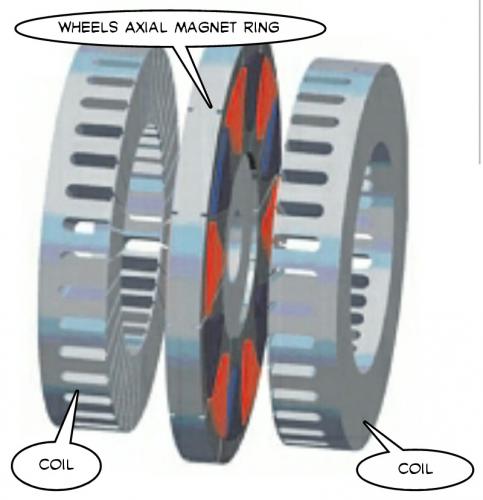
Okay, here's the idea. Build a wheel using either spokes or carbon fiber so that there is a center ring that holds the magnets.
You now add two sets of coils on either side of the wheel. In order to connect the two coils you will likely need to go all the way around the wheel "OR" you can go through the axle. The whole "through the axle" thing is getting really old though.
It's not a true axial flux Halbach potential style configuration, but it does reduce the weight required as part of the wheel inertia, so it would "feel light".
Magnets in the center of the wheel and in between two coil sets on each side.
Flux goes from left to right and not radially. (axially)
The coils on both sides need holes to allow the cassette on one side and the disc brake on the other. Mounting the coils (which have silicon steel laminations) would require some frame attachment. It's the mounting and alignment where some thinking is still required.
Sorta of, kind of, maybe. I see where they are going with that. (referring to previous post)
I'm thinking a very thin and lightweight ring in the wheel that just holds magnets in an Axial orientation.
Then on each side you have separate coils.
It's the "separate coils" idea that is new.
------------------
Basically the wheel can be very lightweight because the magnets are thin and there is no silicon steel or any iron required.
Normally magnets in a radial configuration need some iron to get the flux to "turn".
The image in the previous post does reduce wheel "effective inertia", but they placed the coils on the "inside". So this is an "outside" design.
-------------
It's even possible to consider a SPARSE coil set which uses simple "C" transformer silicon steel laminations.
.
.
Then you can just buy them retail and use carbon fiber to create the shape you need for the coils set overall. (and somehow the coil sets need to attach to the frame)
An axial-flux brushless electric motor which can be used in various applications, including, for example, driving a propulsion wheel of a vehicle. In one embodiment, the electric motor comprises a rotor comprising a plurality of permanent magnets defining a plurality of rotor poles. The electric motor also comprises a stator axially spaced from the rotor and comprising: at least one winding for conducting current; an electronic controller for controlling the current supplied to the at least one winding to rotate the rotor; and consolidating material in which the at least one winding and the electronic controller are embedded.
--------------
This patent covers the type of axial flux motor where the magnets are "outside" the coils.
I'm suggesting the magnets are "inside" the coils which reduces wheel weight and inertia. (50%)
US Patent 20120169154 A1 could be improved with Halbach Arrays. (which might enable a new patent)
------------
.
The mid drive idea has "been around" for some time.
.
The "hub motor concept" begins with a serious DISADVANTAGE compared to the mid drive that passes it's power through multispeed gearing. (a derailler) The disadvantage is caused because all motors operate at a "preferred" set of conditions. With multispeed gearing you can "adapt" to widely varying conditions and still run optimally.
.
.
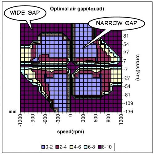
Normally we think of a hub motor as having "fixed behavior", but that doesn't have to be true. The air gap that separates the magnets from the coils determines the overall field strength (amount of magnetic flux) and that flux has a huge effect on motor performance.
An "Axial Flux" design has the potential to implement a "Variable Air Gap". This is the same as "Field Weakening". (same idea)
So if you are even going to bother with a "dying concept" (the hub motor) you should at least be thinking of having a variable air gap. To do that "Axial Flux" makes the most sense. (though some have achieved it using "Radial Flux" too)
It's hard to imagine a better solution than the MID DRIVE.
Since about 2007 I knew it was always my "idealized" solution, but as your typical DIY builder the technical issues associated with building one made it impossible for me to achieve. Now with modern computerized CAD design and high precision engineering we see big manufacturers stepping into the Mid Drive marketplace and we now can have the product we always wanted.
So "thank you" the professional engineer... we (the DIY builder) were kind of in a mental block in our evolution of the ebike and now we are moved fast forward onto the next level.
DIY builders will now begin to "trick out" the Mid Drives and aftermarket kits will surely follow.
First Place goes to the Mid Drive:
High rpm motor
Multispeed gearing (derailler)
Lightweight
Central weight location
High efficiency
Can be backwardly compatible
Makes sense given the 250 watt (750 watt) laws
...no other idea yet realized matches these features.
----------------
This doesn't mean that other ideas aren't possible, but it raises the bar so high that in order to displace the Mid Drive you will need to come up with something really impressive.
Not wanting to "park" this thread with too much of a "fatalistic" sense of the finality of the Mid Drive as the unquestioned winner in this quest I can see another idea.
Fixed drives are just never going to cover the wide range of conditions that ebikes are required to run in. Hills are best dealt with using multispeed gearing and so we still mostly reject fixed gear solutions as inferior. So the Mid Drive still "wins", but it might be improved upon.
The idea would be to have the outer ring carry the magnets in some configuration. It could be radial in which case an "Inrunner" seems the most logical choice. If it's an axial design you can either use magnets to either side (possibly Halbach Arrays) or you can use two sets of coils on each side of magnets in the middle. They all would work, but some might be easier to fabricate than others. Things like bearing tolerances and "slop" would be critical.
The "frame" of the double planetary gear would be fixed.
Gearing needs to "reduce" about 6 to 1 to get best performance.
High pole counts in the 40 pole range or above.
The whole thing would be located at the bottom bracket and take space used for a front sprocket.
It would be a "Mid Drive", but the gear reduction is done as part of the planetary gear.
...if you don't have expensive machine tools don't even bother to try building it. ;)
--------------
Finally, I think it's okay to take that "Spring Fever" Vacation.
Just when you think all the ideas have been uncovered...
There was a company going by the name NagelCraft that was supposed to produce this product. Supposedly the owner had health problems... "or something".
I'm not too concerned with the back story, but there are some ideas to look at.
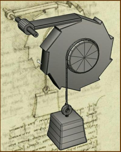
First, the idea of using a "Cam". If you had a high speed electric motor that ran a Cam you would get one or more pulses per rpm.
Second, the idea of using a "Rachet" like you might have in your Freewheel mechanism.
Put the two together and what do you get?
Well, you can now have high rpm that is translated to low rpm. (directly)
For every complete turn of the Cam you get one "click" of the Ratchet.
This is practically like a worm gear it gears down so much. :)
This is one of the best new (to me) ideas to come along for a long time !!!
I'm calling it "The Clicker" because it will sound like it's making a clicking sound when it runs.
The idea is simple... use a Solenoid combined with a Ratchet mechanism so that the Solenoid is only required to have a short stroke and the gear reduction is inherently built into the Ratchet mechanism.
Not only that but this idea already exists.
.
.
Someone MUST build one of these as the ultimate Mid Drive !!!
.
.
I can imagine taking it to the next level and make a Direct Drive Solenoid which better integrates the power side into the Ratcheting side of the system.
Hmmmmmm... what if you could design this in such a way that through computer control you could eliminate much of the Ratchet system? If the Solenoid pulses were perfectly timed they could push the gear and never need to have any contact otherwise.
Back in 2007 my "big prediction" was the Mid Drive because it was capable of multispeed gearing which is pretty much a requirement when laws restrict power.
Now if I were to "predict" the future I'd say this Ratcheting Solenoid could be something that could actually bump the Mid Drives off their pedestal.
In the future we might be viewing "Ratcheting Gears" like it was porn. ;)
That ratcheting solenoid idea was how I was imagining my piezeo comment with having a ring of them attached to each point of a sprocket of a free wheel, coordinated in pairs of freewheel sets for alternating push-push while the other was resetting. Admittedly piezeos would still have too short of a stroke, possibly electro active polymers although a pull arrangement may be needed instead of a push arrangement. My doubt is that there are singular solenoids that can provide useful thrust without weighing several kilo's each. This may be due to a lack of practical experience, but the only solenoids I know personally were not even stronger than my thumb and were still half the size of my fist, perhaps they were defective or under volted. What is the possible power output of a reasonably sized solenoid?
With a hammer, a chisle can be made. With a hammer and chistle, files can be made. With hammer, chisle, and file anything else can be made.
Kaishan k500w retired, Merida TEV500 on indefinite sabbatical, currently using a Currie E-zip Trailz.
The Solenoid is sort of the pure "virginal" magnetic force concept.
It's efficiency is as good as any and since you can focus everything you have electrically into one spot they can be very effective. In FEMM I've been able to get massive straight line forces through simulation. At the most extreme when used in particle accelerator situations they have been able to generate incredible forces with Solenoids.
...this would be for the folks that need the "extra power". ;)
.
I've also noticed that in 1944, George H. Leland, of Dayton, Ohio, created the "Rotary Solenoid" concept which seems to blur the lines of the linear Solenoid and the Ratcheting Solenoid. Not sure if that's worth looking into, but it might prove educational. The idea seems simple enough, you have ball bearings that jump from low point to low point and that drives things in a rotary manner. The forces are probably low however. (forward motion is determined by spring strength)
---------------
Piezo crystals only have a stroke of one millimeter. Unless you could do an "accordion" type stacking of them it's not going to work. But actually, a stack of 100 Piezo crystals would do the job, so it's not a bad idea. That's definitely not a DIY project, so you would need a research lab and lot's of money. I've found that we are limited a great deal by what our fabrication limits are. The Mid Drive was a dream I never realized as a garage mechanic. (now you can buy them, but I tried many times and just broke a lot of parts)
.
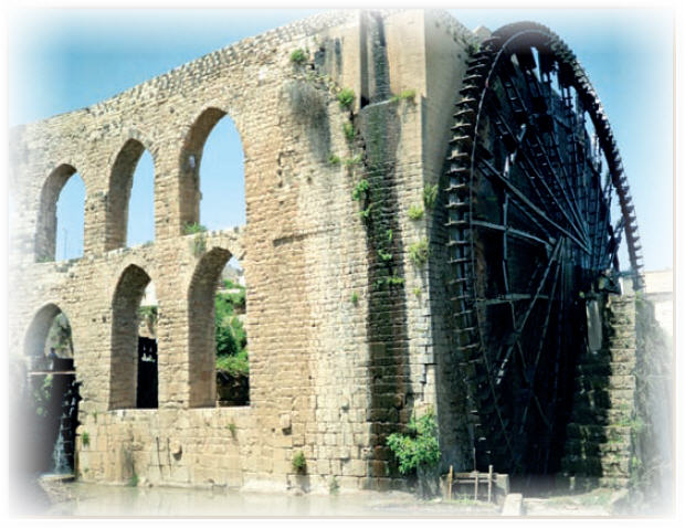
Though the Romans used the "water wheel" extensively, I'm not sure if the "Ratcheting" idea was around back then. Unless it existed earlier I think Leonardo Da Vinci was the true inventor.
.
.
So the idea goes back to at least 1500 AD.
But if people want to make a joke about me "inventing ideas" I'll take credit just for fun. ;)
.
.
It would be nice to be backwardly compatible with existing chainrings.
The problem is that without the gear cog "bias" of a Ratcheting gear there's no natural way to jump from tooth to tooth.
And another question would be:
"Why Bother?"
...since this would interfere with the chain functioning anyway you couldn't use the chainring normally, so you might as well just go with a Ratcheting gear replacement. It can roughly occupy the same space, but just be cut differently.
So this in NOT a direction that makes much sense because it makes it more complicated.
Use one of those high strength front freewheels with multiple Solenoids.
You get the Ratcheting behavior automatically and with symmetric forces on the freewheel it will be more reliable.
A real no-brainer design... easy to build.
Occupies one chainring slot.
.
.
Why can't we just do a "direct drive" radial electric motor with Solenoids?
Well, you could, but the whole point of the Ratcheting capability is to increase Torque by lowering the effective gear ratio. Without the gear reduction you are basically only producing as much Torque as the Solenoid can produce. And given the short effective stroke of a Solenoid the motor in the image is not going to be very efficient.
So we really want and need a Ratcheting freewheel mechanism because it is through it that we gear down and generate larger Torque.
Our stroke needs to be just long enough for one "click" of the freewheel.
.
At some point all ideas must face the "bottom line" analysis.
The first thing to realize is that the stroke of a Solenoid needs to be very short. The shorter you can make the stroke the more efficient the overall system will become because for the same current in the coils you get more force with a narrow gap. This is true for all motors that use gaps between the moving parts, narrow gaps increase magnetic flux significantly.
.
.
These facts drive me towarded a Hinged Solenoid for two reasons:
The stroke of the Solenoid can be amplified using simple leverage
Friction will be very small compared to a sliding cylinder
My "guess" based on the "common wisdom" that each metal to metal contact point introduces an efficiency loss of about 2% suggests that total friction loss should be near 3% at most.
Geardown units on typical Mid Drives involve two stages, so 2%-3% per stage means about 4%-6%, but that can go higher too when you throw in highly stressed undersized bearings and gears.
Overall the idea seems to "pass" the analysis.
**************
One other issue is the "return spring". There is a problem that pops up where a completely closed magnetic flux loop creates it's own "semi-permanent magnet". Once the loop is closed it becomes "sticky". A heavy return spring that is capable of breaking this closed loop takes away from the power stroke, so it's not desireable. One solution is to never allow the gap to close completely by leaving a small space. Fortunately we can skip over this problem if we design the mechanical pawl that contacts the ratcheting gear in such a way that at the end of it's power stroke the Solenoid loop will be disengaged by the arrival of the ratcheting gears next cog.
At this point I have to start thinking of a different name because it's far enough away from the classic "Solenoid" as to have drifted into it's own realm.
By using two coils that face each other you increase efficiency to the maximum possible using iron and copper. This also roughly doubles the size of the effective gap area which increases the force. It begins to look like a Switched Reluctance gap which I know from past studies is a good design for maximizing magnetic flux. (very powerful)
A hinge allows the gap to be opened and closed.
One high tech solution to pop the "sticky" closed loop is to do a quick reverse current pulse to release the hysteresis built up in the silicon steel. That is an alternative to mechanically popping it open. There may be some wisdom in getting rid of the return spring altogether and simply cycle the currents in such a way that 99% is positive (drives the ratcheting mechanism) and 1% returns everything up out of the way. That would reduce any friction that would be caused by a mechanically induced return. Would have to experiment to see which way is better... high tech or low tech.
.
.
You could use standard transformer laminations in the "E" shape. (retail)
Old transformers are everywhere, so you could salvage one easily.
The traditional Solenoid has a wide air gap that shrinks as it functions. By using a standard transformer "D" Core you could change the way the pivot works so that the air gap is constant, but the overall magnetic reluctance varies. There is no "sticking" of the flux loop because the air gap is small, but constant. Since the air gap is never zero we don't have any problems using a light return spring.
.
.
Air Gapped Cores are also available.
This overall change in the concept allows the air gap to be constant and that means that magnetic flux never completely falls off. It "should" make for a more even power stroke. (will need to do some FEMM analysis eventually)
So at this point we have a "Ratcheting Gear" and some kind of constant air gap variable reluctance transformer core that drives the pivot that pushes the pawl into the ratchet gear.
.
.
Update:
This wasn't too hard to find online. "Yes" by using a constant air gap the force becomes constant. I'm sure this will vary slightly depending on how everything is configured, but generally speaking you lose that radical exponential climb in the force of a Solenoid by switching to something with a constant air gap. This makes things much easier.
Afterthought:
Knowing this might actually bring me full circle back to a long Solenoid. If this constant air gap "lip" allows for a longer stroke, then that's the "Holy Grail" that I have sought since I began with the Solenoid idea. (beginning of the thread) It would be far better to have a long Solenoid in the bikes downtube and then use a simple crank in the bottom bracket. But at the same time the "Ratcheting Gear" idea is attractive because it allows for a built in gear reduction and a freewheel mechanism. So it's possible both ideas are good together.
The device shown in Figure 11.20 is sometimes called a constant-force solenoid. Rather than being pulled from the end, with flux lines parallel to the direction of motion, this arrangement operates from changes in the magnetic field around the sides of the plunger, in a manner often referred to as variable-reluctance. As the plunger pulls into a surrounding tube of permeable material, a region of high magnetic flux is set up with a fixed gap distance. The gap region increases linearly with change of plunger position. Since the energy stored in the gap is proportional to volume, and force is proportional to the rate of change of energy with distance, the resulting force on the plunger is, therefore, approximately constant.
One should always try to mate together appropriate level technologies. For instance one would not hack a nuclear ion generator used to propel an interstellar probe onto a paper airplane, would one? Although given the nature of these forums I would not be surprised some dim bulb not unlike yourself will shortly post up a picture that it's been done, just to prove me wrong. None the less, with that in mind here is a suitable candidate vintage bike that would benefit married to 'your' vintage solenoid driven ratchet 'idea'.
A quick review of "where I'm at" with this thought process.
The Mid Drive functions by spinning a small motor very fast. It's like a little girl working out at the gym, she works hard at it and does a lot of reps, but doesn't have much muscle or torque in her workouts.
.
I'm thinking about ways to generate big torque and how I can reduce the rpm to a minimum:
.
.
It would be more like the really huge guy at the gym that lifts the big weights, but fewer reps.
So I'm in a search for the "most concentrated" form of electronic muscle.
Others might be all about dispersing their energies off into the thinnest extent to obtain more leverage, and that's an honest pursuit, but it's just not my train of thought right now.
Saw what?? Is that supposed to be a real award because it looks like some cheap clip art you slapped together. You say that as though you seriously think I'm supposed to be impressed or else conned yourself into believing that it constitutes some sort of proof.
But have you seen this?
.
"Direct drive hubs continue to be the cheapest option, so they will survive in some form simply because of their price.
Geared hubs are a great all-around solution for 80% of new E-bikers. The MAC/eZee/BMC can take 1500W before any cooling mods, and there's a dozen smaller and affordable geared hubs around.
Non-hubs that give the motor some gears (for street and off-road) are the big story for 2014, but they are more complex and expensive, and require occasional shifting. Most customers are happy with a one-speed so they actually have a moped (see MAC 10T @48V). Unless you run off-road or have super-steep hills on your streets, mid drives might end up being only half of new sales by 2015."
.
This comes straight from the horse's mouth, Ron/SpinningMagnets, a writer & researcher over at http://www.electricbike.com/
That ebike webzine's whole editorial pro mid-drive thrust/propoganda as well as Ron's on own personal belief (an ardent mid-drive practioner) is identical to your own propoganda. They routinely just blithely assert mid-drives as being the 'holy-grail' of ebikes like it's some self-evident irrefutable truth handed down from Moses, in much the same way you hand out fake awards. Both of you seek to con unsuspecting noobs to buy into your religion. At least Ron earns some props for at least recognizing where the reality lies (unlike your 'real' reality), & is forced to concede the truth, hedging his bets they won't be the #1 even by next year. Where's you're evidence mid-drive's are #1, have you checked the sales figures at all??
And no, I most definitely do not acknowlege you called anything ahead of the crowd, LOL. You've pushed it back to 1947, keep digging back another half century, you'll get there eventually who called it first.
The idea is that when the coils are activated it creates a magnetic loop that closes the reed switch that then allows for current to flow in the other circuit. In reverse, a small reversing current pops the switch open and terminates the magnetic loop.
.
.
Parallel Path design behaves in a similiar fashion.
It's interesting because they seem to have taken this kind of idea into a very high tech place.
How might this be relevant to what I'm thinking about?
Well, if you had a "known" power stroke and you wanted to switch the magnetic flux "off" at the end of the stroke this type of thinking might work.
Sort of an "end termination brush".
Friction would not be an issue like with ordinary brushes because electrical contact would only occur at the end of the stroke. This would effectively clear any remanence left in the system.
.
With a Solenoid the "pull" comes from the end. The "Constant Force" Solenoid is actually based on Reluctance and so it's actually making magnetic flux lines bend in from the cylinder of the Solenoid and not the end. From past FEMM studies I'd guess the "Constant Force" Solenoid has a fairly low force creation... so it's "constant" but not too impressive.
By going with a higher leverage Reluctance design (above) it should be possible to achieve higher Torque.
If you combine the high Torque with the lengthy leverage and short angular stroke (just a few degrees) you could get that "click" of the Ratcheting Gear.
Still at that "hmmmmmmmmm" stage.
--------------
Note to gSpin:
Hey I'm sorry if the Mid Drives are such a problem for you. They are just beginning to take root as I had hoped for dating back to 2007. (yes, that is a fact)
If you are satisfied with the older technologies that's great !!! Stick to it.
-----------------
This is kind of fun.
I'm not sure what year this is from. Could be 2010 or so.
.
My first attempt at the bike used NiCad batteries, a Mid Drive (through chain), and a Sturmey Archer 8 Speed rear hub. The hub snapped an axle almost immediately ($125) and the motor was burned up on another bike within a week. It took until 2012 to finish the bike with a direct drive and A123 cells. The bike sits in storage today.
.
Some research is being done on a thinned out hub motor that maximizes efficiency while reducing weight as much as possible.
I like the idea !!!
I'm not just a radical thinker for the sake of rebellion. I've tried to do this years ago and found it was way beyond my fabrication skills.
My respect for "conservative design" done exceptionally well is very high.
The Mid Drive was also beyond my DIY skills.
A grinder, a drill, a sander... a hammer... only goes so far.
My understanding is that they are looking into contracting out the work to professionals and that would be a wiser route than DIY for everything.
---------------
I've made this point previously, the professional engineer is capable of pulling off designs that the DIY builder cannot. The Mid Drive would never have come into existence without real engineering. If a thinned out hub motor can be built it could achieve performance that is better than the Mid Drive.
But that's an "if" that hasn't been proven yet... so many designs fail because of fabrication or reliability issues.
The FIA Formula E Championship is designed as an ‘open championship’, inspiring manufacturers and constructors to build their own fully-electric cars, subject to the technical specifications set out by the FIA.
Providing the electric powertrain and electronics is McLaren Electronics Systems, the world leader in high-performance technology for motorsport. Meanwhile, Williams Advanced Engineering, part of the Williams group of companies that includes the world famous Williams F1 Team, will supply the batteries producing 200kw, the equivalent of 270bhp. This will be linked to a paddle shift sequential gearbox, supplied by Hewland, with fixed ratios to help reduce costs further.
-----------------
Interesting:
Here we have the introduction of an electric racing series and it's "Input Limited". (200kw)
On top of that they are effectively doing a "Mid Drive" with multispeed gearing.
Cause and Effect?
If you have an "Input Limit" (Cause) then you have Gears. (Effect)
The magnetic flux will switch back and forth to create a path that runs through one or the other pivot. By using a permanent magnet at the center you overcome most of the "start up cost" of activating the silicon steel and that improves efficiency. It also changes the way the powerband behaves by boosting the early part of the power curve because the magnetic forces caused by the permanent magnet are very high in comparison to the coils.
This type of "magnetic flux switching" occurs in multiple designs, but I haven't found this specific incarnation anywhere, so it may be original. (not sure)
Solenoids have maximimum force at the end of the stroke. This should have strong power earlier in the stroke, so it would be an improvement.
This is looking like your hero Obama's Peace Prize.
A little premature ejaculation.
I don't have any problem with mid-drives, whatever blows the wind your skirt is none of my business. However I do have a big problem with mid-drive Evangalistas preaching mid-drive gospel, passing off baseless assertions as 'fact'.
We'll see how long those gears will last in that Formula E, if it's any longer than your Sturmey8 or whatever & they come to the same conclusion as you did, forced to make a hurried switch to direct drive, as you did. Read up on Tesla (the EV manufacturer) about their experience with gearboxes from 3 different suppliers & why their electric cars don't have one instead chose to stick with single speed. They couldn't get one to last either & that's in a mere family sedan! What chance does a race car have? This is fact.


Sometimes this passion is an addiction...
Okay, here's the idea. Build a wheel using either spokes or carbon fiber so that there is a center ring that holds the magnets.
You now add two sets of coils on either side of the wheel. In order to connect the two coils you will likely need to go all the way around the wheel "OR" you can go through the axle. The whole "through the axle" thing is getting really old though.
It's not a true axial flux Halbach potential style configuration, but it does reduce the weight required as part of the wheel inertia, so it would "feel light".
Magnets in the center of the wheel and in between two coil sets on each side.
Flux goes from left to right and not radially. (axially)
The coils on both sides need holes to allow the cassette on one side and the disc brake on the other. Mounting the coils (which have silicon steel laminations) would require some frame attachment. It's the mounting and alignment where some thinking is still required.
-------------
Hopefully back to Vacation...
.
Something like this?

But this is with single toroidal coils, so as not to loose hardly any magnetic flux in space.
My rides:
2017 Zero S ZF6.5 11kW, erider Thunder 5kW
.
Sorta of, kind of, maybe. I see where they are going with that. (referring to previous post)
I'm thinking a very thin and lightweight ring in the wheel that just holds magnets in an Axial orientation.
Then on each side you have separate coils.
It's the "separate coils" idea that is new.
------------------
Basically the wheel can be very lightweight because the magnets are thin and there is no silicon steel or any iron required.
Normally magnets in a radial configuration need some iron to get the flux to "turn".
The image in the previous post does reduce wheel "effective inertia", but they placed the coils on the "inside". So this is an "outside" design.
-------------
It's even possible to consider a SPARSE coil set which uses simple "C" transformer silicon steel laminations.
.
.
Then you can just buy them retail and use carbon fiber to create the shape you need for the coils set overall. (and somehow the coil sets need to attach to the frame)
It's still very hard work.
------------
A better image:
.
.
Patent
Axial-flux brushless electric motor
US 20120169154 A1
http://www.google.com/patents/US20120169154
.

.
ABSTRACT
An axial-flux brushless electric motor which can be used in various applications, including, for example, driving a propulsion wheel of a vehicle. In one embodiment, the electric motor comprises a rotor comprising a plurality of permanent magnets defining a plurality of rotor poles. The electric motor also comprises a stator axially spaced from the rotor and comprising: at least one winding for conducting current; an electronic controller for controlling the current supplied to the at least one winding to rotate the rotor; and consolidating material in which the at least one winding and the electronic controller are embedded.
--------------
This patent covers the type of axial flux motor where the magnets are "outside" the coils.
I'm suggesting the magnets are "inside" the coils which reduces wheel weight and inertia. (50%)
US Patent 20120169154 A1 could be improved with Halbach Arrays. (which might enable a new patent)
------------
.
The mid drive idea has "been around" for some time.
.
.
The "hub motor concept" begins with a serious DISADVANTAGE compared to the mid drive that passes it's power through multispeed gearing. (a derailler) The disadvantage is caused because all motors operate at a "preferred" set of conditions. With multispeed gearing you can "adapt" to widely varying conditions and still run optimally.
.
.
Normally we think of a hub motor as having "fixed behavior", but that doesn't have to be true. The air gap that separates the magnets from the coils determines the overall field strength (amount of magnetic flux) and that flux has a huge effect on motor performance.
An "Axial Flux" design has the potential to implement a "Variable Air Gap". This is the same as "Field Weakening". (same idea)
So if you are even going to bother with a "dying concept" (the hub motor) you should at least be thinking of having a variable air gap. To do that "Axial Flux" makes the most sense. (though some have achieved it using "Radial Flux" too)
.
.
Time for the "Ebike Propulsion Awards".
.

.
MID DRIVE
It's hard to imagine a better solution than the MID DRIVE.
Since about 2007 I knew it was always my "idealized" solution, but as your typical DIY builder the technical issues associated with building one made it impossible for me to achieve. Now with modern computerized CAD design and high precision engineering we see big manufacturers stepping into the Mid Drive marketplace and we now can have the product we always wanted.
So "thank you" the professional engineer... we (the DIY builder) were kind of in a mental block in our evolution of the ebike and now we are moved fast forward onto the next level.
DIY builders will now begin to "trick out" the Mid Drives and aftermarket kits will surely follow.
First Place goes to the Mid Drive:
...no other idea yet realized matches these features.
----------------
This doesn't mean that other ideas aren't possible, but it raises the bar so high that in order to displace the Mid Drive you will need to come up with something really impressive.
We continue to dream...
.
.
Not wanting to "park" this thread with too much of a "fatalistic" sense of the finality of the Mid Drive as the unquestioned winner in this quest I can see another idea.
Fixed drives are just never going to cover the wide range of conditions that ebikes are required to run in. Hills are best dealt with using multispeed gearing and so we still mostly reject fixed gear solutions as inferior. So the Mid Drive still "wins", but it might be improved upon.
The idea would be to have the outer ring carry the magnets in some configuration. It could be radial in which case an "Inrunner" seems the most logical choice. If it's an axial design you can either use magnets to either side (possibly Halbach Arrays) or you can use two sets of coils on each side of magnets in the middle. They all would work, but some might be easier to fabricate than others. Things like bearing tolerances and "slop" would be critical.
The "frame" of the double planetary gear would be fixed.
Gearing needs to "reduce" about 6 to 1 to get best performance.
High pole counts in the 40 pole range or above.
The whole thing would be located at the bottom bracket and take space used for a front sprocket.
It would be a "Mid Drive", but the gear reduction is done as part of the planetary gear.
...if you don't have expensive machine tools don't even bother to try building it. ;)
--------------
Finally, I think it's okay to take that "Spring Fever" Vacation.
.
.
Just when you think all the ideas have been uncovered...
There was a company going by the name NagelCraft that was supposed to produce this product. Supposedly the owner had health problems... "or something".
I'm not too concerned with the back story, but there are some ideas to look at.
First, the idea of using a "Cam". If you had a high speed electric motor that ran a Cam you would get one or more pulses per rpm.
Second, the idea of using a "Rachet" like you might have in your Freewheel mechanism.
Put the two together and what do you get?
Well, you can now have high rpm that is translated to low rpm. (directly)
For every complete turn of the Cam you get one "click" of the Ratchet.
This is practically like a worm gear it gears down so much. :)
Check it out:
http://vimeo.com/23520898
"Motor -> Cam -> Pushrod -> Ratchet"
.
.
This is one of the best new (to me) ideas to come along for a long time !!!
I'm calling it "The Clicker" because it will sound like it's making a clicking sound when it runs.
The idea is simple... use a Solenoid combined with a Ratchet mechanism so that the Solenoid is only required to have a short stroke and the gear reduction is inherently built into the Ratchet mechanism.
Not only that but this idea already exists.
.
.
Someone MUST build one of these as the ultimate Mid Drive !!!
.
.
I can imagine taking it to the next level and make a Direct Drive Solenoid which better integrates the power side into the Ratcheting side of the system.
Hmmmmmm... what if you could design this in such a way that through computer control you could eliminate much of the Ratchet system? If the Solenoid pulses were perfectly timed they could push the gear and never need to have any contact otherwise.
The "Smart Solenoid?"
.
.
.
Very simple concept:
Solenoid, a gear with a directional bias, some small spring tension that swings the Solenoid toward the gear and that's about it.
You just pulse the Solenoid once for each cog of the gear and that gives a gear ratio equal to whatever tooth count you choose.
Very nice. :)
High Torque without High Rpm or much Weight.
Perfect for a Mid Drive.
I'm the first to ever invent it too !!!
.
.
(kidding... "What have the Romans ever done for us?")
.
Back in 2007 my "big prediction" was the Mid Drive because it was capable of multispeed gearing which is pretty much a requirement when laws restrict power.
Now if I were to "predict" the future I'd say this Ratcheting Solenoid could be something that could actually bump the Mid Drives off their pedestal.
In the future we might be viewing "Ratcheting Gears" like it was porn. ;)
(oh, you know what I'm talking about)
.
.
.
That ratcheting solenoid idea was how I was imagining my piezeo comment with having a ring of them attached to each point of a sprocket of a free wheel, coordinated in pairs of freewheel sets for alternating push-push while the other was resetting. Admittedly piezeos would still have too short of a stroke, possibly electro active polymers although a pull arrangement may be needed instead of a push arrangement. My doubt is that there are singular solenoids that can provide useful thrust without weighing several kilo's each. This may be due to a lack of practical experience, but the only solenoids I know personally were not even stronger than my thumb and were still half the size of my fist, perhaps they were defective or under volted. What is the possible power output of a reasonably sized solenoid?
With a hammer, a chisle can be made. With a hammer and chistle, files can be made. With hammer, chisle, and file anything else can be made.
Kaishan k500w retired, Merida TEV500 on indefinite sabbatical, currently using a Currie E-zip Trailz.
The Solenoid is sort of the pure "virginal" magnetic force concept.
It's efficiency is as good as any and since you can focus everything you have electrically into one spot they can be very effective. In FEMM I've been able to get massive straight line forces through simulation. At the most extreme when used in particle accelerator situations they have been able to generate incredible forces with Solenoids.
So it just comes down to proper sizing.
.

.
http://en.m.wikipedia.org/wiki/Solenoid
.
...this would be for the folks that need the "extra power". ;)
.

I've also noticed that in 1944, George H. Leland, of Dayton, Ohio, created the "Rotary Solenoid" concept which seems to blur the lines of the linear Solenoid and the Ratcheting Solenoid. Not sure if that's worth looking into, but it might prove educational. The idea seems simple enough, you have ball bearings that jump from low point to low point and that drives things in a rotary manner. The forces are probably low however. (forward motion is determined by spring strength)
---------------
Piezo crystals only have a stroke of one millimeter. Unless you could do an "accordion" type stacking of them it's not going to work. But actually, a stack of 100 Piezo crystals would do the job, so it's not a bad idea. That's definitely not a DIY project, so you would need a research lab and lot's of money. I've found that we are limited a great deal by what our fabrication limits are. The Mid Drive was a dream I never realized as a garage mechanic. (now you can buy them, but I tried many times and just broke a lot of parts)
.
.
.
I want to establish the "root" of this idea.
Though the Romans used the "water wheel" extensively, I'm not sure if the "Ratcheting" idea was around back then. Unless it existed earlier I think Leonardo Da Vinci was the true inventor.
.
.
So the idea goes back to at least 1500 AD.
But if people want to make a joke about me "inventing ideas" I'll take credit just for fun. ;)
.
.
It would be nice to be backwardly compatible with existing chainrings.
The problem is that without the gear cog "bias" of a Ratcheting gear there's no natural way to jump from tooth to tooth.
And another question would be:
"Why Bother?"
...since this would interfere with the chain functioning anyway you couldn't use the chainring normally, so you might as well just go with a Ratcheting gear replacement. It can roughly occupy the same space, but just be cut differently.
So this in NOT a direction that makes much sense because it makes it more complicated.
A Ratcheting gear replacement is preferred.
.
.
This is good for the DIY builder.
Use one of those high strength front freewheels with multiple Solenoids.
You get the Ratcheting behavior automatically and with symmetric forces on the freewheel it will be more reliable.
A real no-brainer design... easy to build.
Occupies one chainring slot.
.
.
Why can't we just do a "direct drive" radial electric motor with Solenoids?
Well, you could, but the whole point of the Ratcheting capability is to increase Torque by lowering the effective gear ratio. Without the gear reduction you are basically only producing as much Torque as the Solenoid can produce. And given the short effective stroke of a Solenoid the motor in the image is not going to be very efficient.
So we really want and need a Ratcheting freewheel mechanism because it is through it that we gear down and generate larger Torque.
Our stroke needs to be just long enough for one "click" of the freewheel.
.
.
At some point all ideas must face the "bottom line" analysis.
The first thing to realize is that the stroke of a Solenoid needs to be very short. The shorter you can make the stroke the more efficient the overall system will become because for the same current in the coils you get more force with a narrow gap. This is true for all motors that use gaps between the moving parts, narrow gaps increase magnetic flux significantly.
.
.
These facts drive me towarded a Hinged Solenoid for two reasons:
---------------------------------------------------
Friction:
...there are few moving parts.
.
My "guess" based on the "common wisdom" that each metal to metal contact point introduces an efficiency loss of about 2% suggests that total friction loss should be near 3% at most.
Geardown units on typical Mid Drives involve two stages, so 2%-3% per stage means about 4%-6%, but that can go higher too when you throw in highly stressed undersized bearings and gears.
Overall the idea seems to "pass" the analysis.
**************
One other issue is the "return spring". There is a problem that pops up where a completely closed magnetic flux loop creates it's own "semi-permanent magnet". Once the loop is closed it becomes "sticky". A heavy return spring that is capable of breaking this closed loop takes away from the power stroke, so it's not desireable. One solution is to never allow the gap to close completely by leaving a small space. Fortunately we can skip over this problem if we design the mechanical pawl that contacts the ratcheting gear in such a way that at the end of it's power stroke the Solenoid loop will be disengaged by the arrival of the ratcheting gears next cog.
We got lucky. :)
.
.
At this point I have to start thinking of a different name because it's far enough away from the classic "Solenoid" as to have drifted into it's own realm.
By using two coils that face each other you increase efficiency to the maximum possible using iron and copper. This also roughly doubles the size of the effective gap area which increases the force. It begins to look like a Switched Reluctance gap which I know from past studies is a good design for maximizing magnetic flux. (very powerful)
A hinge allows the gap to be opened and closed.
One high tech solution to pop the "sticky" closed loop is to do a quick reverse current pulse to release the hysteresis built up in the silicon steel. That is an alternative to mechanically popping it open. There may be some wisdom in getting rid of the return spring altogether and simply cycle the currents in such a way that 99% is positive (drives the ratcheting mechanism) and 1% returns everything up out of the way. That would reduce any friction that would be caused by a mechanically induced return. Would have to experiment to see which way is better... high tech or low tech.
.
.
You could use standard transformer laminations in the "E" shape. (retail)
Old transformers are everywhere, so you could salvage one easily.
.
.
Never underestimate the value of simplicity.
The traditional Solenoid has a wide air gap that shrinks as it functions. By using a standard transformer "D" Core you could change the way the pivot works so that the air gap is constant, but the overall magnetic reluctance varies. There is no "sticking" of the flux loop because the air gap is small, but constant. Since the air gap is never zero we don't have any problems using a light return spring.
.
.
Air Gapped Cores are also available.
This overall change in the concept allows the air gap to be constant and that means that magnetic flux never completely falls off. It "should" make for a more even power stroke. (will need to do some FEMM analysis eventually)
So at this point we have a "Ratcheting Gear" and some kind of constant air gap variable reluctance transformer core that drives the pivot that pushes the pawl into the ratchet gear.
.
.
Update:
This wasn't too hard to find online. "Yes" by using a constant air gap the force becomes constant. I'm sure this will vary slightly depending on how everything is configured, but generally speaking you lose that radical exponential climb in the force of a Solenoid by switching to something with a constant air gap. This makes things much easier.
Afterthought:
Knowing this might actually bring me full circle back to a long Solenoid. If this constant air gap "lip" allows for a longer stroke, then that's the "Holy Grail" that I have sought since I began with the Solenoid idea. (beginning of the thread) It would be far better to have a long Solenoid in the bikes downtube and then use a simple crank in the bottom bracket. But at the same time the "Ratcheting Gear" idea is attractive because it allows for a built in gear reduction and a freewheel mechanism. So it's possible both ideas are good together.
.
.
I'll let the website do the talking:
http://www.consult-g2.com/course/chapter11/chapter.html
The device shown in Figure 11.20 is sometimes called a constant-force solenoid. Rather than being pulled from the end, with flux lines parallel to the direction of motion, this arrangement operates from changes in the magnetic field around the sides of the plunger, in a manner often referred to as variable-reluctance. As the plunger pulls into a surrounding tube of permeable material, a region of high magnetic flux is set up with a fixed gap distance. The gap region increases linearly with change of plunger position. Since the energy stored in the gap is proportional to volume, and force is proportional to the rate of change of energy with distance, the resulting force on the plunger is, therefore, approximately constant.
-------------------
I wish I knew of this on page one...
.
One should always try to mate together appropriate level technologies. For instance one would not hack a nuclear ion generator used to propel an interstellar probe onto a paper airplane, would one? Although given the nature of these forums I would not be surprised some dim bulb not unlike yourself will shortly post up a picture that it's been done, just to prove me wrong. None the less, with that in mind here is a suitable candidate vintage bike that would benefit married to 'your' vintage solenoid driven ratchet 'idea'.
http://gizmodo.com/348866/high-school-student-builds-100-wooden-bike
.
You saw that right?
Basically this might be a "game over" situation.
I'm just fiddling around with alternative ideas.
At least acknowledge that in 2007 I called the Mid Drive ahead of the majority of people out there.
Can you give credit for me being right far in advance?
.
A quick review of "where I'm at" with this thought process.
The Mid Drive functions by spinning a small motor very fast. It's like a little girl working out at the gym, she works hard at it and does a lot of reps, but doesn't have much muscle or torque in her workouts.
.
I'm thinking about ways to generate big torque and how I can reduce the rpm to a minimum:
.
.
It would be more like the really huge guy at the gym that lifts the big weights, but fewer reps.
So I'm in a search for the "most concentrated" form of electronic muscle.
Others might be all about dispersing their energies off into the thinnest extent to obtain more leverage, and that's an honest pursuit, but it's just not my train of thought right now.
.
Saw what?? Is that supposed to be a real award because it looks like some cheap clip art you slapped together. You say that as though you seriously think I'm supposed to be impressed or else conned yourself into believing that it constitutes some sort of proof.
But have you seen this?
.
"Direct drive hubs continue to be the cheapest option, so they will survive in some form simply because of their price.
Geared hubs are a great all-around solution for 80% of new E-bikers. The MAC/eZee/BMC can take 1500W before any cooling mods, and there's a dozen smaller and affordable geared hubs around.
Non-hubs that give the motor some gears (for street and off-road) are the big story for 2014, but they are more complex and expensive, and require occasional shifting. Most customers are happy with a one-speed so they actually have a moped (see MAC 10T @48V). Unless you run off-road or have super-steep hills on your streets, mid drives might end up being only half of new sales by 2015."
.
This comes straight from the horse's mouth, Ron/SpinningMagnets, a writer & researcher over at http://www.electricbike.com/
That ebike webzine's whole editorial pro mid-drive thrust/propoganda as well as Ron's on own personal belief (an ardent mid-drive practioner) is identical to your own propoganda. They routinely just blithely assert mid-drives as being the 'holy-grail' of ebikes like it's some self-evident irrefutable truth handed down from Moses, in much the same way you hand out fake awards. Both of you seek to con unsuspecting noobs to buy into your religion. At least Ron earns some props for at least recognizing where the reality lies (unlike your 'real' reality), & is forced to concede the truth, hedging his bets they won't be the #1 even by next year. Where's you're evidence mid-drive's are #1, have you checked the sales figures at all??
And no, I most definitely do not acknowlege you called anything ahead of the crowd, LOL. You've pushed it back to 1947, keep digging back another half century, you'll get there eventually who called it first.
.
This Ferreed Switch is interesting.
The idea is that when the coils are activated it creates a magnetic loop that closes the reed switch that then allows for current to flow in the other circuit. In reverse, a small reversing current pops the switch open and terminates the magnetic loop.
.
.
Parallel Path design behaves in a similiar fashion.
This website:
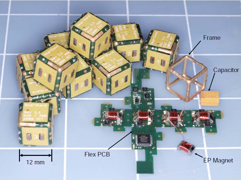
http://www.hizook.com/blog/2010/12/07/electropermanent-magnets-programmable-magnets-zero-static-power-consumption-enable-s
.
.
It's interesting because they seem to have taken this kind of idea into a very high tech place.
How might this be relevant to what I'm thinking about?
Well, if you had a "known" power stroke and you wanted to switch the magnetic flux "off" at the end of the stroke this type of thinking might work.
Sort of an "end termination brush".
Friction would not be an issue like with ordinary brushes because electrical contact would only occur at the end of the stroke. This would effectively clear any remanence left in the system.
.
.
Reluctance is a different way to generate Torque.
With a Solenoid the "pull" comes from the end. The "Constant Force" Solenoid is actually based on Reluctance and so it's actually making magnetic flux lines bend in from the cylinder of the Solenoid and not the end. From past FEMM studies I'd guess the "Constant Force" Solenoid has a fairly low force creation... so it's "constant" but not too impressive.
By going with a higher leverage Reluctance design (above) it should be possible to achieve higher Torque.
If you combine the high Torque with the lengthy leverage and short angular stroke (just a few degrees) you could get that "click" of the Ratcheting Gear.
Still at that "hmmmmmmmmm" stage.
--------------
Note to gSpin:
Hey I'm sorry if the Mid Drives are such a problem for you. They are just beginning to take root as I had hoped for dating back to 2007. (yes, that is a fact)
If you are satisfied with the older technologies that's great !!! Stick to it.
-----------------
This is kind of fun.
I'm not sure what year this is from. Could be 2010 or so.
.
My first attempt at the bike used NiCad batteries, a Mid Drive (through chain), and a Sturmey Archer 8 Speed rear hub. The hub snapped an axle almost immediately ($125) and the motor was burned up on another bike within a week. It took until 2012 to finish the bike with a direct drive and A123 cells. The bike sits in storage today.
.
.
...truly a trip down memory lane. :)
.
.
"Conservative" is not an ugly word to me.
http://endless-sphere.com/forums/viewtopic.php?f=30&t=57371
Some research is being done on a thinned out hub motor that maximizes efficiency while reducing weight as much as possible.
I like the idea !!!
I'm not just a radical thinker for the sake of rebellion. I've tried to do this years ago and found it was way beyond my fabrication skills.
My respect for "conservative design" done exceptionally well is very high.
The Mid Drive was also beyond my DIY skills.
A grinder, a drill, a sander... a hammer... only goes so far.
My understanding is that they are looking into contracting out the work to professionals and that would be a wiser route than DIY for everything.
---------------
I've made this point previously, the professional engineer is capable of pulling off designs that the DIY builder cannot. The Mid Drive would never have come into existence without real engineering. If a thinned out hub motor can be built it could achieve performance that is better than the Mid Drive.
But that's an "if" that hasn't been proven yet... so many designs fail because of fabrication or reliability issues.
.
.
http://www.fiaformulae.com/guide/car
The FIA Formula E Championship is designed as an ‘open championship’, inspiring manufacturers and constructors to build their own fully-electric cars, subject to the technical specifications set out by the FIA.
Providing the electric powertrain and electronics is McLaren Electronics Systems, the world leader in high-performance technology for motorsport. Meanwhile, Williams Advanced Engineering, part of the Williams group of companies that includes the world famous Williams F1 Team, will supply the batteries producing 200kw, the equivalent of 270bhp. This will be linked to a paddle shift sequential gearbox, supplied by Hewland, with fixed ratios to help reduce costs further.
-----------------
Interesting:
Here we have the introduction of an electric racing series and it's "Input Limited". (200kw)
On top of that they are effectively doing a "Mid Drive" with multispeed gearing.
Cause and Effect?
If you have an "Input Limit" (Cause) then you have Gears. (Effect)
This seems to be a pattern.
...still looking really good.
.
.
In order to remove the need for a return spring.
The magnetic flux will switch back and forth to create a path that runs through one or the other pivot. By using a permanent magnet at the center you overcome most of the "start up cost" of activating the silicon steel and that improves efficiency. It also changes the way the powerband behaves by boosting the early part of the power curve because the magnetic forces caused by the permanent magnet are very high in comparison to the coils.
This type of "magnetic flux switching" occurs in multiple designs, but I haven't found this specific incarnation anywhere, so it may be original. (not sure)
Solenoids have maximimum force at the end of the stroke. This should have strong power earlier in the stroke, so it would be an improvement.
The two pivots would be mechanically linked.
Coils would exist too.
.
This is looking like your hero Obama's Peace Prize.

A little premature ejaculation.
I don't have any problem with mid-drives, whatever blows the wind your skirt is none of my business. However I do have a big problem with mid-drive Evangalistas preaching mid-drive gospel, passing off baseless assertions as 'fact'.
We'll see how long those gears will last in that Formula E, if it's any longer than your Sturmey8 or whatever & they come to the same conclusion as you did, forced to make a hurried switch to direct drive, as you did. Read up on Tesla (the EV manufacturer) about their experience with gearboxes from 3 different suppliers & why their electric cars don't have one instead chose to stick with single speed. They couldn't get one to last either & that's in a mere family sedan! What chance does a race car have? This is fact.
Pages