The bidirectional solenoid both pushes and pulls and with sprag clutches in both directions one is always doing work while the other is ratcheting backwards.
What's nice is that it would make a smoother output and eliminate the need for the return spring.
Add in the fact that you cut the sprag clutch wear in half because they share the load which means you might use a lighter weight set.
Very good... and it's good to see pictures.
Five stars for animations. (that's the next level... more work to do though)
-------------------
Solenoids that actually function as push and pull are not that common. I drew up an example of how one might be designed:
.
.
...it might also be possible to use a magnet as the core.
I'm also considering a more radial design like my last sketch, but with a magnet so I could eliminate the mechanical spring.
---------------
However, I really do like the dual sprag clutch idea because it eliminates rebound "slap" as the single sprag clutch resets itself. By having two counter rotating sprag clutches one is always under load and that means power deliver will be very smooth.
The biggest complaint seems to be noisy mid drive motors and the dual sprag clutch should reduce noise because of the smoother power delivery.
Very nice. :)
.
.
Going back to the invention that prompted the "Ratchet Gear Porn" in the first place we also saw double ratchets. But those were conventional ratchets that would be fairly noisy.
Glad that you got it. Nothing like a drawing to explain an idea.
Note that the two arms of the sprag clutches could also be oriented to be side-by-side, but not close together.
Then, you can put a pivoted bellcrank between the two arms so that when one goes forward, the other goes backward. Attach the solenoid to one end.
It's so hard to communicate with words. When you wrote "pivoted bellcrank" I literally had to do a google search because it could have meant anything as far as I was concerned.
I think I get your idea. With the "pivoted bellcrank" you could achieve leverage which is important with some solenoids that have very short strokes.
A hint on double posting... press the button once and when it begins sending wait for like 5 minutes because the admins here want to discourage spam posters and they put in long delays sometimes. Once you get in the "Edit" functionality is quick.
Try looking at the Lavet type stepping motor and see if you can imagine it being integrated into the design. What makes it interesting is that the magnet drives most of the magnetic flux and only a small startup energy is required by the coils to get it to "flip".
It seems we are in a situation where we could use this and get past the awkwardness of a bidirectional solenoid with short stroke.
There is a whole class of magnetic systems that work well in a simple sine wave situation, so we should consider them. Parallel Path ideas work much like the Lavet.
Use magnetic repulsion to push the rebound stroke. Since the Sprag Clutch takes very little energy to "click backward" you use magnetic repulsion that DECREASES with distance. At the end of this stroke you reverse the electromagnet and begin to slowly engage the rollers. By the time all the slack is taken up you now can pull harder and harder into the power stroke.
No friction. Nothing to wear out. Power seems to be in the right places at the right times.
It might be necessary to have an "end stop" magnet on the rebound side to keep it from overshooting. A spring could work too, but if we start going frictionless you might as well stick to it.
Yes, maybe I should have written pivoted lever, or ... Hmmm
I meant just a bar that links both levers together, and there is a pivot in the center of the bar that affixes it to the frame. So when one end of the lever goes forward, the other end goes backward.
I'm not sure about the Lavet stepper... I think the force from residual reluctance is very low. If you want any speed, you cannot wait for the sprags to slowly reset after every stroke.
And about the repulsion rebounder, aren't you depending a "spring" again?
I think it would be better to actively drive the sprags in both directions to get speed and power.
Do you think it would be possible to make a bi-directional solenoid fron two horseshoe cores or magnets placed face to face? Maybe place a moveable rotor in the gap between the two pieces?
The Lavet stepper is in the same class as Parallel Path ideas in that they can generate significantly higher magnetic flux with less activation energy in the coils. The reason those systems are effective is that the permanent magnet does most of the "work". It's possibly too complicated for this situation, but I've always liked the idea.
The Repulsion Rebounder idea is based on a single sprag clutch. With repulsion the force naturally decreases with distance which is what is wanted. When you attract magnetically the forces increase as you get closer which is exactly what you don't want. I like the simplicity and that it's entirely without friction other than the singular sprag clutch.
.
.
.
.
The images above show an example of a bidirectional solenoid like device. Sometimes when no one does something (bidirectional solenoid) it's for a reason. The problem can be traced to making good magnetic flux in both directions. The traditional solenoid is only good in one direction. The example above exploits the bending of flux lines in the middle and that gives something to grab onto magnetically. It's one of those things that with a lot of FEMM experimenting you realize it's not an easy thing to solve.
You might be better off with two independently running solenoids.
.
.
You might review the "Faraday Paradox".
I know I got stuck on that one. Basically a solenoid is a "magnetic flux concentrator" but forces are only made when you cut across perpendicular to the flux lines. A solenoid only makes a force as it "exits" it's little tube.
.
I want to do a quick review of how magnetic flux actually creates a force.
.
.
The solenoid has this remarkable property that it focuses, amplifies and concentrates magnetic flux. The natural inclination is to view flux as a sort of "fluid" which is either at high pressure or low pressure. Unfortunately that "simplified model" doesn't actually work because of the Faraday Paradox.
Instead we learn that magnetic flux has a sort of "grain" like wood which can generate forces if you cut across the grain, but NOT if you cut along the grain.
Switched Reluctance Motors are the easiest way to visually see forces being created because the act of "bending the grain" of the magnetic flux creates a resulting force.
.
.
The solenoid is actually a very deceptive device. It "looks" as though the plunger is "attracted" to the end without bending any magnetic flux lines. One thinks:
"If the magnetic flux isn't being bent how can a force get generated?"
...but the reason is very subtle. Magnetic flux likes to find a "lower effort path". It's like with electricity a charge will naturally seek the path of least resistance and actually divert energies from other areas toward whatever is easiest.
.
.
The solenoid is actually functioning in a way to "reduce" it's magnetic flux as a whole within the context of the system. It's the overall reduction of magnetic flux that creates the force.
For each incremental reduction in magnetic flux resistance we gain an incremental force output.
In the case of the "constant force" solenoid they use a plunger with a constant air gap and that sets a sort of maximum on the force possible because the gap itself creates a resistance. This is why in electric motors a close air gap tends to be preferred because it means you create higher magnetic flux, but in some cases people have created variable air gap motors that behave like "field weakening" motors. You would do that to widen your effective powerband.
Anyway... solenoids have strengths and weaknesses...
.
Hi,
On the repulsion rebounder, I understand that the magnetic force is inversely proportional to the square of the distance.
But for actuating a sprag clutch, wouldn't it be preferable to have a constant force with distance ?
Because as soon as the clutch engages, and for the whole of its stroke, it acts as a locked device with the shaft.
So the clutch will turn at the same RPM as the shaft, and will have to supply a torque equal to the drag on the shaft.
Note that when the clutch recoils, the shaft doesn't stop turning because of the inertia of the bike.
The clutch will NOT be easier to drive at the beginning of its stroke than at the end.
Thanks for the explanation on solenoids and mag force in general.
Effectively, the solenoid doesn't work like we think it does. I've tried to apply the Left Hand Rule to it without success.
About (switched) reluctance motors, I've recently taken a look at them for a project un-related to EVs, and they seem very interesting.
It's a pity they are not more popular. They're so simple, and now with the availability of control ICs, easy to implement.
I believe that they would be ideal for a very high RPM motor, say around 60,000-75,000, and 4-5KW...right?
Unfortunately, magnetics is not my expertise area.
But for actuating a sprag clutch, wouldn't it be preferable to have a constant force with distance ?
Yes, I agree, if you had the ability to control the force "at will" you would want:
1) A slower, lower powered initial contact phase which engages the sprag clutch and gets it to a fully locked position.
2) A constant force phase where the majority of the power gets delivered.
3) A drop off of force at the end so you don't slam magnets together.
--------------------
At this point there is a fork in design possibilities...
A) You can use dual sprag clutches so that one is always in a power stroke while the other is rebounding.
B) You can reverse the current of the electromagnet on a single sprag clutch and get it to rebound. You need to somehow get it to have an endpoint which makes it bounce back so there is either a spring or another opposing magnet at the end of the rebound. I like the idea of an opposing magnet on the end because it's silent and frictionless and if you "overshoot" with your electromagnet you get that energy back. (so you don't actually waste energy)
.
I believe that they would be ideal for a very high RPM motor, say around 60,000-75,000, and 4-5KW...right?
Switched Reluctance can achieve very high rpm.
The big problem with it is the same problem as with a solenoid.
With a solenoid you only make power when magnetic flux resistance is declining.
With a permanent magnet you can make power as it approaches an electromagnet, but then suddenly reverse polarity as you pass so that what begins as a pull turns into a push.
Switched Reluctance is like a four stroke gasoline motor. (power in just 25% of cycle)
Permanent Magnets are like two stroke gasoline motors. (power in 50% of cycle)
----------------
Taking this truth and applying it to this problem of the sprag clutch we might think of something like a pendulum with a permanent magnet on the end and an electromagnet. If you switch the polarity of the electromagnet at the right times you can control every aspect of it's forces.
You could either go with a single or dual sprag clutch configuration. (though actually I can't see how to get to dual from here)
Position sensors might be the way to go... even in the single sprag clutch case you should be able to switch polarity fast enough because of sensor processing to get what you want.
There would be a tradeoff between torque (a longer pendulum) verses rotation achieved in the sprag clutch. Once you know the general "looseness" of the sprag clutch you can determine the maximum torque you could produce while still actually making some rotation happen. If not enough rotation is performed I'd guess the sprag clutch will just latch and unlatch and make no actual rpm.
.
At that point, I'm wondering if it wouldn't be better to forget the solenoid and drive the dual Sprags with an electric motor attached to a small crankshaf with 2 connecting rods (vertical twin crank).
We kind of have to go back to "why" a ratchet has benefits that an electric motor does not.
Power = Torque * RPM
In a small motor Torque tends to be small and RPM is very high.
The basic idea of the ratchet is to maximize Torque so you can lower RPM.
A solenoid is very effective in creating a straight line Force in one direction only.
Torque = Force * Leverage
...all we are doing by going with a Pendulum is allowing for Torque in both directions.
(so it's pretty good)
Think of it like you are taking a 24 pole pair motor and extracting just one of those pole pairs and then ballooning it up to a much larger size to increase Torque. All the Torque is generated in one place rather than being spread out over 24 pole pairs.
It's very compact... in fact I think it could simply be bolted to the innermost chainring... the "granny gear". Then the electromagnet could be bolted to the frames downtube. The whole thing would only weigh a few pounds as far as I can figure. The true test would be a full FEMM simulation where I would measure the Force and Torque it generates. You really don't know until you get a simulation if the ideas are any good.
----------------
But I'm certain the Sprag Clutch is a superior idea to clicking ratchets. On my ebike I actually was using a "Roller Clutch" that was undersized. The "Roller Clutch" has been used on bicycle hubs before.
.
.
"Roller Clutches" are generally known to be inferior to "Sprag Clutches". The difference is that the Sprag Clutch uses actual springs, but the Roller Clutch sort let's things wiggle around and hope they align okay.
--------------
The Pendulum Sprag Clutch doesn't need a stroke any longer than it takes to achieve forward motion on the output. We actually want a very low rpm... about 90 rpm... and no ordinary motor is going to spin so slowly without having a very high pole count and needing way too much room.
.
.
...something like this could work. Mechanical leverage could be good.
EXACTLY!
By using an electric motor and a small crankshaft driving the two arms of the dual sprag, we get all the advantages!
I cannot make a drawing, but on the drawing above, rotate one of the two clutches so both arms are side-by-side. And position them so they point up.
Now, place the crankshaft at the left of the arms, on the same centerline, and connect each of the connecting rods to an arm of the clutch.
So when the crank rotates, it will "wiggle" the arms and the clutches will transmit power to the output shaft.
You don't need a slow RPM to activate the clutches because if the crankshaft has a small stroke, and the clutches have long arms, you get a very high reduction ratio and high torque.
The motor can therefore be used in its most powerful RPM range.
The advantage of the motor is that it gives you variable torque, which was difficult to get with solenoids.
Don't calculate gear ratio like that.
With this system, there is NO limit to the theoretical gear ratio.
Just imagine that if the two arms of the clutch were veeeeeeeeeeryyyyyyyyyy long, the stroke of the crankshaft very short, then the angular displacement of the the clutches would be of the order of a hundred of a degree or less for each turn of the crankshaft.
Just make a simple drawing of it and it will become clear...
Just create a cam that rotates with the motor. You can make a longer or shorter stroke depending on how long the cam is and the shape of the area it travels through. A roller at the end of the cam would reduce friction. (not shown)
We agree that this is a mid drive right?
At the end of all this we want about 100 rpm at the sprag clutch.
Yes, that would be for a mid drive.
If the (theoretical)clutch advances one hundreth of a degree per revolution of the motor, it means that it will take 36000 revolutions to get one turn on the clutch. Gear ratio: 36000:1 !
With a 6000RPM motor, you then get 0.166 RPM...
On a real-world drive, there will not be any problem obtaining 100 RPM.
The "slop" (hysteresis) is much less than 10 degs.
I have one here that has practically none at all.
It depends on the design of the clutch. The ones that have spring-loaded rollers (cams) have no slop. They engage immediately.
The Roller Clutch absolutely, positively had "slop" even when new and it went downhill after about 100 miles of testing. It never slipped during that period, but I could tell it wouldn't last long.
It does make sense that with spring loading that even if the Sprag Clutch wears a little that the springs will actively compensate.
.
.
It still seems to me that the Pendulum Sprag Clutch is frictionless and extremely simple. There are no real limits to the very direct magnet-to-electromagnet system but I can understand the desire to be able to actually "buy" something and try it in real life. Talking theory is great, but life changes dramatically when you get into the garage and start building stuff.
So are you considering actually trying it?
I like all these ideas (anything with a ratchet in it) and would like to see something built.
You just never know with these things. If in testing it's discovered this works well it could completely alter the direction that mid drives develop. For the most part the mid drives being built resemble very old and conservative designs. The ratchet, as a concept, is quite unusual.
On one hand there is what appears to be a very viable option using off the shelf RC motors, a twin crank, and dual sprag clutches. We don't have the great graphic for it yet, but at some point we will. This idea seems fully buildable right now without too much fuss.
-----------------
On the more abstract and idealized side (not easily buildable with present options) the Pendulum Sprag Clutch has many benefits.
.
.
If you consider the UNEQUAL power requirements for the forward and rebound stroke you come upon a new revelation:
.
.
Every time an electromagnet is used it takes a certain amount of power to "charge up" the material.
When you expend your "First Reversal" of energy to demagnetize the material this represents your first truly wasteful act. In a perfect world you would turn off the power and all the magnetism would disappear, but because of hysteresis there is a residual "Remanence" that needs to be purged from the system.
If you cycle from full positive to full negative magnetic polarity you have a "First Reversal" AND a "Second Reversal" which doubles the losses.
So the surprising find is that since real power is only needed in one direction you actually never are forced to waste energy on a major "Second Reversal". A trivial rebound pulse, just enough to reset the sprag clutch is all that's needed and that saves energy.
This would require that the controller has UNEQUAL power cycles. (unique)
...which means you could actually think about either driving the system 50% harder than usual or reducing it's size by 50%. In essence you pull half of the negatives out while only running half the time.
-------------
If you drive on both forward and backwards strokes with a dual sprag clutch design you double your power output while also doubling your energy requirements.
So in the final comparison efficiency is about the same, with friction being the only difference.
The Pendulum Sprag Clutch approach is mechanically less complex, has less friction and probably is more durable because of fewer moving parts. The Dual Sprag Clutch with RC motor has a lot of friction, but is less difficult for a DIY builder to put together despite actually being more mechanically complex. That mechanical complexity is "bought not built".
.
Last night while "sleeping" I realized that we didn't need a separate crankshaft between the motor and the clutches.
The crank could be the motor shaft itself. The motor has a shaft at each end. So each end has an offset pin to which is attached the connecting rod that goes to the arm of the clutch. Super simple.
However, because the arms are actuated via a crank and a connecting rod, like the pistons move in a gas engine, their movement in time follows a quasi-sinusoidal curve.
That means that they go slow at the beginning of stroke, accelerate to a max at mid-stroke, and decelerate to zero before changing direction.
As the output shaft that is driven by the clutches has a relatively constant speed, it means that the clutches will be engaged for only a small portion of the stroke.
This is not necessarily bad in itself, although not optimum. At least not worse than the power strokes in a four-stroke engine that produce power for only about 1/6 of the total cycle.
So the magnetically driven clutch has the excellent feature that the clutch will be engaged for almost the whole length of the stroke.
Before stumbling onto this thread, I had considered building myself a mid-drive with a brushless DC motor and a worm drive (I know the efficiency is lower) but finally decided to order a Bafang drive (that I have not received yet) because of lack of time to develop a new system. I have other big projects, and my business that are taking all my time. And here in Quebec, summer is short.
It would be very interesting however to try the clutch drive. The simplest way would be to remove the pedals from a bike and put the drive in its place. For testing purposes, pedals are not needed anyway.
On your pendulum drive with a single clutch, I think that the electronics should put out a short pulse of opposite polarity at the end of the stroke. That will eliminate remanence and help the return stroke.
But I think I would still prefer having 2 clutches and a bi-directional pendulum.
By adding another pole to your U-core to make it double-U, and a third coil, you would make it bi-directional.
I started this hobby before the whole concept really was in existence back in 2006.
After some 10,000 miles on a multispeed roughly 1000 watt ebike I've been mostly out of the actual fabrication and riding side now and do the hobby as an intellectual challenge.
My good fortunes in life have also allowed me to still be healthy enough to ride a regular bicycle without power. I'll ride three hours a day and just love it.
The problem with ebikes is they are almost "too good" and you don't have to work out if you don't want to.
Reliability has been a big problem with all these ebikes. You will probably discover this summer that something will wear out and you will be spending time fixing things. That's why I stress the simplicity and potential long term reliability more based on my experience.
.
.
I would suggest you just have fun with the Bafang this summer and save this Sprag Clutch idea for winter when you have time to do it. (assuming you have a workspace in winter)
I'm toying with getting back into it (building) but not sure yet.
I chose the Bafang because it is the most quiet, and it seems quite reliable.
But I'm sure I'll modify it at some time. I think there's not a single thing that I bought in my life, that I have not modified/repaired at some point.
The thing I don't like about the Bafang is that you cannot have a very small sprocket at the front. So you're limited in climbing ability.
I'm not after speed on my mountain bike, rather the contrary. I like going in small trails through very rocky terrain, and the slow speed performance is the most important for me. I want it to climb like a tractor... Like a trials bike. (I own a Sherco). If I can't modify it to my taste, I'll resell it and make a different one.
One thing I would like to integrate is regeneration. And eliminate the derailleur.
Second try.
Okay, I can see that.
The bidirectional solenoid both pushes and pulls and with sprag clutches in both directions one is always doing work while the other is ratcheting backwards.
What's nice is that it would make a smoother output and eliminate the need for the return spring.
Add in the fact that you cut the sprag clutch wear in half because they share the load which means you might use a lighter weight set.
Very good... and it's good to see pictures.
Five stars for animations. (that's the next level... more work to do though)
-------------------
Solenoids that actually function as push and pull are not that common. I drew up an example of how one might be designed:
.
.
...it might also be possible to use a magnet as the core.
I'm also considering a more radial design like my last sketch, but with a magnet so I could eliminate the mechanical spring.
---------------
However, I really do like the dual sprag clutch idea because it eliminates rebound "slap" as the single sprag clutch resets itself. By having two counter rotating sprag clutches one is always under load and that means power deliver will be very smooth.
The biggest complaint seems to be noisy mid drive motors and the dual sprag clutch should reduce noise because of the smoother power delivery.
Very nice. :)
.
.
Going back to the invention that prompted the "Ratchet Gear Porn" in the first place we also saw double ratchets. But those were conventional ratchets that would be fairly noisy.
.
Glad that you got it. Nothing like a drawing to explain an idea.
Note that the two arms of the sprag clutches could also be oriented to be side-by-side, but not close together.
Then, you can put a pivoted bellcrank between the two arms so that when one goes forward, the other goes backward. Attach the solenoid to one end.
Double post
.
It's so hard to communicate with words. When you wrote "pivoted bellcrank" I literally had to do a google search because it could have meant anything as far as I was concerned.
I think I get your idea. With the "pivoted bellcrank" you could achieve leverage which is important with some solenoids that have very short strokes.
A hint on double posting... press the button once and when it begins sending wait for like 5 minutes because the admins here want to discourage spam posters and they put in long delays sometimes. Once you get in the "Edit" functionality is quick.

.
.
http://en.m.wikipedia.org/wiki/Lavet_type_stepping_motor
Try looking at the Lavet type stepping motor and see if you can imagine it being integrated into the design. What makes it interesting is that the magnet drives most of the magnetic flux and only a small startup energy is required by the coils to get it to "flip".
It seems we are in a situation where we could use this and get past the awkwardness of a bidirectional solenoid with short stroke.
There is a whole class of magnetic systems that work well in a simple sine wave situation, so we should consider them. Parallel Path ideas work much like the Lavet.
.
.
This is another idea.
Use magnetic repulsion to push the rebound stroke. Since the Sprag Clutch takes very little energy to "click backward" you use magnetic repulsion that DECREASES with distance. At the end of this stroke you reverse the electromagnet and begin to slowly engage the rollers. By the time all the slack is taken up you now can pull harder and harder into the power stroke.
No friction. Nothing to wear out. Power seems to be in the right places at the right times.
It might be necessary to have an "end stop" magnet on the rebound side to keep it from overshooting. A spring could work too, but if we start going frictionless you might as well stick to it.
.
Yes, maybe I should have written pivoted lever, or ... Hmmm
I meant just a bar that links both levers together, and there is a pivot in the center of the bar that affixes it to the frame. So when one end of the lever goes forward, the other end goes backward.
I'm not sure about the Lavet stepper... I think the force from residual reluctance is very low. If you want any speed, you cannot wait for the sprags to slowly reset after every stroke.
And about the repulsion rebounder, aren't you depending a "spring" again?
I think it would be better to actively drive the sprags in both directions to get speed and power.
Do you think it would be possible to make a bi-directional solenoid fron two horseshoe cores or magnets placed face to face? Maybe place a moveable rotor in the gap between the two pieces?
The Lavet stepper is in the same class as Parallel Path ideas in that they can generate significantly higher magnetic flux with less activation energy in the coils. The reason those systems are effective is that the permanent magnet does most of the "work". It's possibly too complicated for this situation, but I've always liked the idea.
The Repulsion Rebounder idea is based on a single sprag clutch. With repulsion the force naturally decreases with distance which is what is wanted. When you attract magnetically the forces increase as you get closer which is exactly what you don't want. I like the simplicity and that it's entirely without friction other than the singular sprag clutch.
.
.
.
.
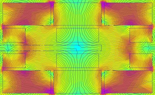
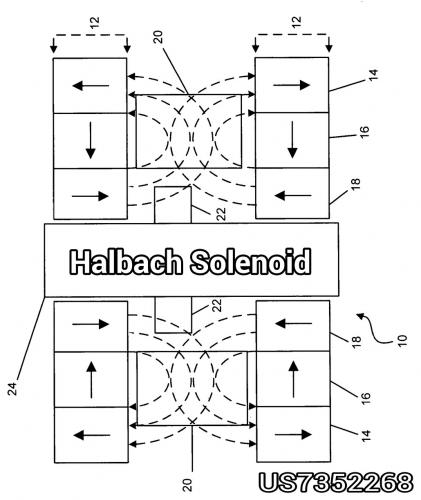
The images above show an example of a bidirectional solenoid like device. Sometimes when no one does something (bidirectional solenoid) it's for a reason. The problem can be traced to making good magnetic flux in both directions. The traditional solenoid is only good in one direction. The example above exploits the bending of flux lines in the middle and that gives something to grab onto magnetically. It's one of those things that with a lot of FEMM experimenting you realize it's not an easy thing to solve.
You might be better off with two independently running solenoids.
.
.
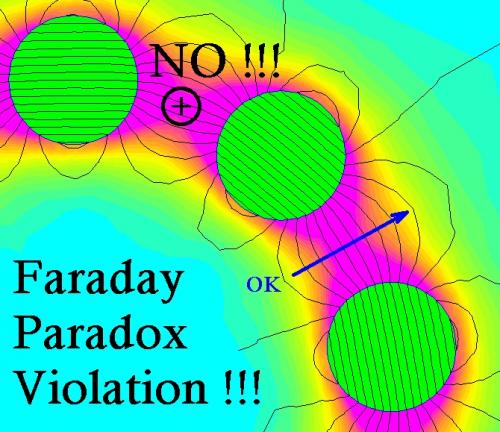
You might review the "Faraday Paradox".
I know I got stuck on that one. Basically a solenoid is a "magnetic flux concentrator" but forces are only made when you cut across perpendicular to the flux lines. A solenoid only makes a force as it "exits" it's little tube.
.
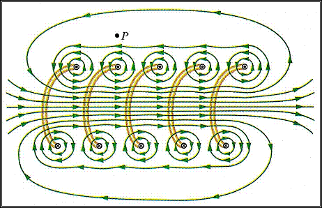
I want to do a quick review of how magnetic flux actually creates a force.
.
.
The solenoid has this remarkable property that it focuses, amplifies and concentrates magnetic flux. The natural inclination is to view flux as a sort of "fluid" which is either at high pressure or low pressure. Unfortunately that "simplified model" doesn't actually work because of the Faraday Paradox.
Instead we learn that magnetic flux has a sort of "grain" like wood which can generate forces if you cut across the grain, but NOT if you cut along the grain.
Switched Reluctance Motors are the easiest way to visually see forces being created because the act of "bending the grain" of the magnetic flux creates a resulting force.
.

.
The solenoid is actually a very deceptive device. It "looks" as though the plunger is "attracted" to the end without bending any magnetic flux lines. One thinks:
"If the magnetic flux isn't being bent how can a force get generated?"
...but the reason is very subtle. Magnetic flux likes to find a "lower effort path". It's like with electricity a charge will naturally seek the path of least resistance and actually divert energies from other areas toward whatever is easiest.
.

.
The solenoid is actually functioning in a way to "reduce" it's magnetic flux as a whole within the context of the system. It's the overall reduction of magnetic flux that creates the force.
For each incremental reduction in magnetic flux resistance we gain an incremental force output.
In the case of the "constant force" solenoid they use a plunger with a constant air gap and that sets a sort of maximum on the force possible because the gap itself creates a resistance. This is why in electric motors a close air gap tends to be preferred because it means you create higher magnetic flux, but in some cases people have created variable air gap motors that behave like "field weakening" motors. You would do that to widen your effective powerband.
Anyway... solenoids have strengths and weaknesses...
.
Hi,
On the repulsion rebounder, I understand that the magnetic force is inversely proportional to the square of the distance.
But for actuating a sprag clutch, wouldn't it be preferable to have a constant force with distance ?
Because as soon as the clutch engages, and for the whole of its stroke, it acts as a locked device with the shaft.
So the clutch will turn at the same RPM as the shaft, and will have to supply a torque equal to the drag on the shaft.
Note that when the clutch recoils, the shaft doesn't stop turning because of the inertia of the bike.
The clutch will NOT be easier to drive at the beginning of its stroke than at the end.
Thanks for the explanation on solenoids and mag force in general.
Effectively, the solenoid doesn't work like we think it does. I've tried to apply the Left Hand Rule to it without success.
About (switched) reluctance motors, I've recently taken a look at them for a project un-related to EVs, and they seem very interesting.
It's a pity they are not more popular. They're so simple, and now with the availability of control ICs, easy to implement.
I believe that they would be ideal for a very high RPM motor, say around 60,000-75,000, and 4-5KW...right?
Unfortunately, magnetics is not my expertise area.
Yes, I agree, if you had the ability to control the force "at will" you would want:
1) A slower, lower powered initial contact phase which engages the sprag clutch and gets it to a fully locked position.
2) A constant force phase where the majority of the power gets delivered.
3) A drop off of force at the end so you don't slam magnets together.
--------------------
At this point there is a fork in design possibilities...
A) You can use dual sprag clutches so that one is always in a power stroke while the other is rebounding.
B) You can reverse the current of the electromagnet on a single sprag clutch and get it to rebound. You need to somehow get it to have an endpoint which makes it bounce back so there is either a spring or another opposing magnet at the end of the rebound. I like the idea of an opposing magnet on the end because it's silent and frictionless and if you "overshoot" with your electromagnet you get that energy back. (so you don't actually waste energy)
.
Switched Reluctance can achieve very high rpm.
The big problem with it is the same problem as with a solenoid.
With a solenoid you only make power when magnetic flux resistance is declining.
With a permanent magnet you can make power as it approaches an electromagnet, but then suddenly reverse polarity as you pass so that what begins as a pull turns into a push.
Switched Reluctance is like a four stroke gasoline motor. (power in just 25% of cycle)
Permanent Magnets are like two stroke gasoline motors. (power in 50% of cycle)
----------------
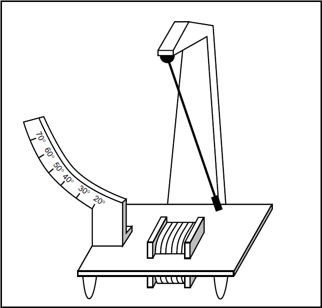
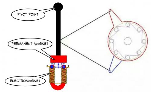
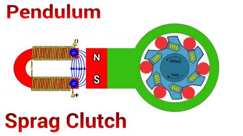
Taking this truth and applying it to this problem of the sprag clutch we might think of something like a pendulum with a permanent magnet on the end and an electromagnet. If you switch the polarity of the electromagnet at the right times you can control every aspect of it's forces.
.
.
.
This is the sort of thing I come up with.
You could either go with a single or dual sprag clutch configuration. (though actually I can't see how to get to dual from here)
Position sensors might be the way to go... even in the single sprag clutch case you should be able to switch polarity fast enough because of sensor processing to get what you want.
There would be a tradeoff between torque (a longer pendulum) verses rotation achieved in the sprag clutch. Once you know the general "looseness" of the sprag clutch you can determine the maximum torque you could produce while still actually making some rotation happen. If not enough rotation is performed I'd guess the sprag clutch will just latch and unlatch and make no actual rpm.
.
At that point, I'm wondering if it wouldn't be better to forget the solenoid and drive the dual Sprags with an electric motor attached to a small crankshaf with 2 connecting rods (vertical twin crank).
.
We kind of have to go back to "why" a ratchet has benefits that an electric motor does not.
Power = Torque * RPM
In a small motor Torque tends to be small and RPM is very high.
The basic idea of the ratchet is to maximize Torque so you can lower RPM.
A solenoid is very effective in creating a straight line Force in one direction only.
Torque = Force * Leverage
...all we are doing by going with a Pendulum is allowing for Torque in both directions.
(so it's pretty good)
Think of it like you are taking a 24 pole pair motor and extracting just one of those pole pairs and then ballooning it up to a much larger size to increase Torque. All the Torque is generated in one place rather than being spread out over 24 pole pairs.
It's very compact... in fact I think it could simply be bolted to the innermost chainring... the "granny gear". Then the electromagnet could be bolted to the frames downtube. The whole thing would only weigh a few pounds as far as I can figure. The true test would be a full FEMM simulation where I would measure the Force and Torque it generates. You really don't know until you get a simulation if the ideas are any good.
----------------
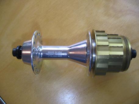
But I'm certain the Sprag Clutch is a superior idea to clicking ratchets. On my ebike I actually was using a "Roller Clutch" that was undersized. The "Roller Clutch" has been used on bicycle hubs before.
.
.
"Roller Clutches" are generally known to be inferior to "Sprag Clutches". The difference is that the Sprag Clutch uses actual springs, but the Roller Clutch sort let's things wiggle around and hope they align okay.
--------------
The Pendulum Sprag Clutch doesn't need a stroke any longer than it takes to achieve forward motion on the output. We actually want a very low rpm... about 90 rpm... and no ordinary motor is going to spin so slowly without having a very high pole count and needing way too much room.
.
.
...something like this could work. Mechanical leverage could be good.
.
EXACTLY!
By using an electric motor and a small crankshaft driving the two arms of the dual sprag, we get all the advantages!
I cannot make a drawing, but on the drawing above, rotate one of the two clutches so both arms are side-by-side. And position them so they point up.
Now, place the crankshaft at the left of the arms, on the same centerline, and connect each of the connecting rods to an arm of the clutch.
So when the crank rotates, it will "wiggle" the arms and the clutches will transmit power to the output shaft.
You don't need a slow RPM to activate the clutches because if the crankshaft has a small stroke, and the clutches have long arms, you get a very high reduction ratio and high torque.
The motor can therefore be used in its most powerful RPM range.
The advantage of the motor is that it gives you variable torque, which was difficult to get with solenoids.
You realize that most small motors (like an RC motor) run best at 6000 rpm right?
In order to get to 100 rpm you need to divide the sprag clutch stroke into 60 steps.
360 degrees in a circle divided by 60 is just 6 degrees of rotation per motor rotation.
----------------
If that's possible (6 degrees per stroke) you might be onto something.
The sprag clutches just become a very unusual geardown unit.
If you do dual sprag clutches then it would actually be just 3 degrees each.
(which seems unlikely)
.

.
Going the other way with the math and with a single sprag clutch...
A 30 degree stroke means 6 strokes per revolution and 600 per minute at 100 rpm.
.
Don't calculate gear ratio like that.
With this system, there is NO limit to the theoretical gear ratio.
Just imagine that if the two arms of the clutch were veeeeeeeeeeryyyyyyyyyy long, the stroke of the crankshaft very short, then the angular displacement of the the clutches would be of the order of a hundred of a degree or less for each turn of the crankshaft.
Just make a simple drawing of it and it will become clear...
.
This might be easier.
Just create a cam that rotates with the motor. You can make a longer or shorter stroke depending on how long the cam is and the shape of the area it travels through. A roller at the end of the cam would reduce friction. (not shown)
We agree that this is a mid drive right?
At the end of all this we want about 100 rpm at the sprag clutch.
.
That was actually the criticism I was trying to make.
What is the practical rotation angle required to overcome sprag clutch "slop".
...my experience with Roller Clutches is that it takes about 15 degrees to guarantee a solid lock.
Maybe the Sprag Clutch tolerances are less, but they aren't zero.
I'd guess a design of 10 degrees is about the minimum.
.
Yes, that would be for a mid drive.
If the (theoretical)clutch advances one hundreth of a degree per revolution of the motor, it means that it will take 36000 revolutions to get one turn on the clutch. Gear ratio: 36000:1 !
With a 6000RPM motor, you then get 0.166 RPM...
On a real-world drive, there will not be any problem obtaining 100 RPM.
The "slop" (hysteresis) is much less than 10 degs.
I have one here that has practically none at all.
It depends on the design of the clutch. The ones that have spring-loaded rollers (cams) have no slop. They engage immediately.
They sound great.
I've never had one in my hand to know.
The Roller Clutch absolutely, positively had "slop" even when new and it went downhill after about 100 miles of testing. It never slipped during that period, but I could tell it wouldn't last long.
It does make sense that with spring loading that even if the Sprag Clutch wears a little that the springs will actively compensate.
.
.
It still seems to me that the Pendulum Sprag Clutch is frictionless and extremely simple. There are no real limits to the very direct magnet-to-electromagnet system but I can understand the desire to be able to actually "buy" something and try it in real life. Talking theory is great, but life changes dramatically when you get into the garage and start building stuff.
So are you considering actually trying it?
I like all these ideas (anything with a ratchet in it) and would like to see something built.
You just never know with these things. If in testing it's discovered this works well it could completely alter the direction that mid drives develop. For the most part the mid drives being built resemble very old and conservative designs. The ratchet, as a concept, is quite unusual.
.
So we seem to have come upon a fork in the road.
On one hand there is what appears to be a very viable option using off the shelf RC motors, a twin crank, and dual sprag clutches. We don't have the great graphic for it yet, but at some point we will. This idea seems fully buildable right now without too much fuss.
-----------------
On the more abstract and idealized side (not easily buildable with present options) the Pendulum Sprag Clutch has many benefits.
.

.
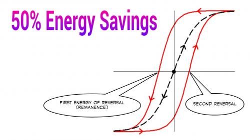
If you consider the UNEQUAL power requirements for the forward and rebound stroke you come upon a new revelation:
.
.
Every time an electromagnet is used it takes a certain amount of power to "charge up" the material.
When you expend your "First Reversal" of energy to demagnetize the material this represents your first truly wasteful act. In a perfect world you would turn off the power and all the magnetism would disappear, but because of hysteresis there is a residual "Remanence" that needs to be purged from the system.
If you cycle from full positive to full negative magnetic polarity you have a "First Reversal" AND a "Second Reversal" which doubles the losses.
So the surprising find is that since real power is only needed in one direction you actually never are forced to waste energy on a major "Second Reversal". A trivial rebound pulse, just enough to reset the sprag clutch is all that's needed and that saves energy.
This would require that the controller has UNEQUAL power cycles. (unique)
Some benefits include:
Reduced copper heating (50% less)
Reduced silicon steel heating (50% less)
Reduced controller MOSFET heating (50% less)
...which means you could actually think about either driving the system 50% harder than usual or reducing it's size by 50%. In essence you pull half of the negatives out while only running half the time.
-------------
If you drive on both forward and backwards strokes with a dual sprag clutch design you double your power output while also doubling your energy requirements.
So in the final comparison efficiency is about the same, with friction being the only difference.
The Pendulum Sprag Clutch approach is mechanically less complex, has less friction and probably is more durable because of fewer moving parts. The Dual Sprag Clutch with RC motor has a lot of friction, but is less difficult for a DIY builder to put together despite actually being more mechanically complex. That mechanical complexity is "bought not built".
.
Last night while "sleeping" I realized that we didn't need a separate crankshaft between the motor and the clutches.
The crank could be the motor shaft itself. The motor has a shaft at each end. So each end has an offset pin to which is attached the connecting rod that goes to the arm of the clutch. Super simple.
However, because the arms are actuated via a crank and a connecting rod, like the pistons move in a gas engine, their movement in time follows a quasi-sinusoidal curve.
That means that they go slow at the beginning of stroke, accelerate to a max at mid-stroke, and decelerate to zero before changing direction.
As the output shaft that is driven by the clutches has a relatively constant speed, it means that the clutches will be engaged for only a small portion of the stroke.
This is not necessarily bad in itself, although not optimum. At least not worse than the power strokes in a four-stroke engine that produce power for only about 1/6 of the total cycle.
So the magnetically driven clutch has the excellent feature that the clutch will be engaged for almost the whole length of the stroke.
Before stumbling onto this thread, I had considered building myself a mid-drive with a brushless DC motor and a worm drive (I know the efficiency is lower) but finally decided to order a Bafang drive (that I have not received yet) because of lack of time to develop a new system. I have other big projects, and my business that are taking all my time. And here in Quebec, summer is short.
It would be very interesting however to try the clutch drive. The simplest way would be to remove the pedals from a bike and put the drive in its place. For testing purposes, pedals are not needed anyway.
On your pendulum drive with a single clutch, I think that the electronics should put out a short pulse of opposite polarity at the end of the stroke. That will eliminate remanence and help the return stroke.
But I think I would still prefer having 2 clutches and a bi-directional pendulum.
By adding another pole to your U-core to make it double-U, and a third coil, you would make it bi-directional.
I had not read your last post before writing my last paragraph above... so I'll rethink that.
AH ! Now I know why I had not seen the text. You edited your post and added the text.
The Bafang mid drive should be fun.
I started this hobby before the whole concept really was in existence back in 2006.
After some 10,000 miles on a multispeed roughly 1000 watt ebike I've been mostly out of the actual fabrication and riding side now and do the hobby as an intellectual challenge.
My good fortunes in life have also allowed me to still be healthy enough to ride a regular bicycle without power. I'll ride three hours a day and just love it.
The problem with ebikes is they are almost "too good" and you don't have to work out if you don't want to.
Reliability has been a big problem with all these ebikes. You will probably discover this summer that something will wear out and you will be spending time fixing things. That's why I stress the simplicity and potential long term reliability more based on my experience.
.
.
I would suggest you just have fun with the Bafang this summer and save this Sprag Clutch idea for winter when you have time to do it. (assuming you have a workspace in winter)
I'm toying with getting back into it (building) but not sure yet.
The hobby is very addictive...
.
I chose the Bafang because it is the most quiet, and it seems quite reliable.
But I'm sure I'll modify it at some time. I think there's not a single thing that I bought in my life, that I have not modified/repaired at some point.
The thing I don't like about the Bafang is that you cannot have a very small sprocket at the front. So you're limited in climbing ability.
I'm not after speed on my mountain bike, rather the contrary. I like going in small trails through very rocky terrain, and the slow speed performance is the most important for me. I want it to climb like a tractor... Like a trials bike. (I own a Sherco). If I can't modify it to my taste, I'll resell it and make a different one.
One thing I would like to integrate is regeneration. And eliminate the derailleur.
Pages