I see that you haven't understood my post.
There is no way that the solenoid can "slam" itself into the walls at the end of the stroke, because its speed is LIMITED by the clutch, and that speed is relatively slow.
With a Hall effect sensor determining the end-of-stroke position, the solenoid reverses direction and instantaneously the other clutch engages, again limiting the speed of that return stroke.
If the POSITION of the plunger is plotted against TIME on a graph, it will draw a nice triangular waveform.
The changes of direction at the end of strokes are done smoothly and silently.
You can know when it's time to turn the power off because the sensor let's you know what is going on.
Initially I was assuming a sensorless design (for everything) so having natural rebounding seemed the most logical way to keep things running as planned.
If the "device" has no natural limits to it's stroke then it will just keep extending.
Which actually leads me to the next problem about the dual sprag clutch... "friction":
.
.
In our earlier design:
.
.
...and just ignore the "propulsion device" and focus on the Forces that are created by the two struts that connect to the levers coming off the sprag clutches.
When one is "loaded" the other is not. This is a problem.
Actually this pendulum idea isn't that bad because the pivot holds the intersection point in one spot. Had this been our more solenoid like diagram then the reaction forces of one strut that is "free" and another that is "loaded" will produce a twisting torque that would cause friction, especially if the solenoid is anything like a shock absorber in mechanical design. (smooth long shaft)
.
.
The "push-pull" idea would involve the "force device" being fixed to the bike, but at least when the device operated the imbalanced forces will at least cause limited friction.
If this is the way to go then an entirely different electrical force creating "device" needs to be looked into as an alternative.
The single and dual sprag clutch designs seem to cause things to drift apart.
Single seems to go best with an "oscillator". (sine wave)
Dual seems to go best with "push-pull". (linear)
...but I will have to try out the pendulum approach in FEMM. That hasn't been simulated yet and it's the easiest to do. The "push-pull" design has a subtle problem in that you need a "floating linkage" of some sort to correct for rotation, so the pendulum might be the way to go.
.
This begins to really create a potential "product".
The fact that the silicon steel is now wrapped around the sprag clutch means you have the room you need for copper which means lower copper losses at the price of a little more weight, but this is very light to begin with, so we can splurge.
Very, very compact.
It might be possible to use the right side bottom bracket threads as a mount. Just pull out the stock right side cup and install one that holds the coil in place. You might need an extra brace, but that's easy to do.
The 2 linkages between the solenoid and the clutches do not apply anymore.
About one week ago I described a system with only one linkage, with the 2 clutch arms placed side by side, and a small lever between the two.
Anyway, this will necessitate a reduction drive before going to the crankwheel.
The sprags direct on the crankwheel will not be powerful enough.
The 2 linkages between the solenoid and the clutches do not apply anymore.
About one week ago I described a system with only one linkage, with the 2 clutch arms placed side by side, and a small lever between the two. There is no un-aligned forces, so no friction.
Anyway, this will necessitate a reduction drive before going to the crankwheel.
The sprags direct on the crankwheel will not be powerful enough.
The sprags direct on the crankwheel will not be powerful enough.
.
.
The truth is it's hard to know without deeper study.
The way small motors achieve impressive power is through high rpm. If you can switch rapidly and at a higher current level you produce more power. This is the basis of just about every motor, electric or gas, to simply spin faster.
So it's not a simple calculation for "power".
I know when I was rewinding the old Unite motors it took a while to get the feel of all the parameters and limitations involved. In some cases I'd so completely saturate the iron that I'd be wasting at least 50% of the energy producing nothing but heat. (which usually ended up destroying the motor)
Efficiency always seems to occur when there is a balance of all the losses... not too much current or too little or too much speed or too little. Typically the conventional motor reaches it's best overall efficiency at about 75% of it's maximum speed.
Having the option to shorten the stroke means you can blast away at higher current... which means a higher voltage (technically a higher duty cycle percentage with PWM), and since it doesn't have to go as far it can be quick.
It's still a little fuzzy to me (variable stroke length) but I think it's possible to "emulate" different gear ratios with it.
.
.
In "regular" electric motors there is a sine wave relationship of a coil and a magnet. If you were to create a Single Phase motor it would have a Force relationship with it's power such that maximum Force occurs in a narrow zone as the coil and magnet are near each other.
Three Phase (and above) motors overlap multiple "shifted" coils so that the normally sine wave relationship is smoothed out and power becomes more continuous... but ironically this trick actually means that the copper "resource pool" gets diluted and rather than having a massive peak of Force you spread it out. Obviously this depends on the design, but generally this is the case.
Linear relationships, such as a Solenoid, "can" exist, but you actually have less peak Force in those because they typically rely on a fixed air gap. Flat ended Solenoids actually allow the air gap to shrink to zero which is why they have high Force at the end, but they make lousy alternating polarity devices. (better for opening or closing something just once)
So in an oscillator it's peak Force... it's "sweet spot"... is in a narrow range in the middle.
This means if you want to exploit the full potential of the magnet-to-coil relationship you need to hit the peak MANY times per second.
Small motors actually are doing this by spinning at high rpm.
Think of the magnet as a "resource" that can be used once per second or 100 times per second. If you can use the same "resource" more often it's as though you multiplied it.
------------------
Higher efficiency can be part of the overall powerband dynamics (complex) or it can be a change in the design or behavior of the system.
Motors are often specifically designed to run best at a certain speed.
They do this by carefully adjusting the rate of current so that it matches the natural "time constant" of the motor. In a "perfect world" the current matches what the motor "wants".
So in this oscillator in "power mode" you would ram current through at higher frequency and higher current to maximize the magnets. In "efficiency mode" you lower the frequency and drop the current to just enough to deliver the minimum Force required.
.
.
Given this knowledge we ask:
"Why not increase the pole count to infinity?"
Up to a point increasing pole count is a great idea. After all, the more magnetic pole pairs you have means that the switching is taking place faster which means each magnet is being exploited more often which produces more power. A win, win.
But as some point you hit a wall... either the iron has problems with hysteresis switching so fast (heat wasted) or you simply can't get the MOSFETS in the controller to handle the insane frequencies that are required.
So we want to have the ability to increase our switching rate... but within limits.
.
Getting back to how one might create a "true to life" push-pull (expanding and contracting) device with magnets, I have tried many times to make one in FEMM but haven't done well.
It seems the most natural solution would involve magnets that are set up to oppose each other so that oscillation can occur between them, but they are not inclined to bang into each other.
.
.
The thinking would go that you would somehow "extract" concentrations of flux in one area creating a kind of vacuum, then flood the other zones with excess flux to create a pressure area. The "problem" is how to actually do that without having flux leak all over the place.
I have no good answer.
.
.
This is interesting...
I moved the copper coils into the center between two magnets pointed at each other.
Notice how the magnetic flux is forced to "tunnel" in between.
If this can be properly exploited so that all the energy is focused inward it looks like a possible direction to go in. Normally one would try to spin the magnetic flux outward and use a lot of silicon steel to get any power out of it.
At some point I need to actually go through the math...
Power = Torque * Speed
As it applies to the Sprag Clutch concept we can observe certain things:
Torque is defined as .
.
.
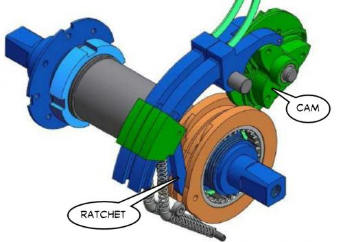
So when we look at the "root idea" cam system we see that they actually had an adjustable Torque capability because the length of the lever could be changed while in use. At present I'm not thinking of doing that, but it's there if needed.
What we can adjust is the Speed or "Angular Velocity". Since the Sprag Clutch has no set ratchet spacing and an oscillator device can vary it's stroke it's possible to change the Speed of the Sprag Clutch relative to the oscillation frequency.
As I see it you would begin by discovering the MINIMUM stroke length the Sprag Clutch is capable of while still maintaining an actual forward motion. You need this knowledge because this represents the MINIMUM oscillation stroke that can be applied when at full Power and at low Speed.
Once this minimum is known you can design the leverage so as to maximize the Radius component of Torque. This means that at maximum oscillation frequency the system overall produces the maximum power.
...which is strange.
Normally we match our maximum oscillation frequency of our "motor device" so that it exists at the maximum speed of our system. So we would be inverting the normal behavior.
Since we are already "maxed out" in our oscillation frequency and power at our lowest speed we have no way to increase speed through increased oscillation rates.
"So how do we increase speed?"
We increase speed by INCREASING the stroke length of the Sprag Clutch while DECREASING the oscillation rate. Force is created because of the "rate of change" of magnetic flux in the system ("Faradays Paradox") so if we wanted to have the same "rate of change" at lower frequency we would need to drive the currents LONGER which means more copper loss heat and likely saturation of the iron. Since this extra "waste" is not helpful we simply conceed that as the speed increases we must LOWER our expectations for the Force component. (so we actually slow the rate of current applied)
The net effect would be a system whose Torque is highest at low Speed and that Torque declines as the Speed increases. However, the current is "bound" more tightly at low Speed because under those conditions the oscillation frequency is highest. Hysteresis losses would flip and be highest at low speed as would copper losses.
On a regular PM motor they "burn up" at low Speed and low oscillation frequency, but the Hysteresis component is good at low speed and bad at high, so it's more balanced.
"Low end torque" motors do exist and one example is the Induction motor that actually works best at low speed and then fades out as speed increases.
But for a mid drive we might be able to just design for a single speed, so this option might not be required.
...not sure if I answered my own question or opened a can of worms.
.
At this point I need to do a review of some electric motor types.
The first permanent magnet types (which are the most common) are defined by their magnet strength. The slope of the line will match some measure of the magnet strength and stronger magnets produce more torque for the same current. In real life one doesn't typically run a permanent motor "wide open" like this because of excess heat that is created (the controller limits this) but this is the absolute torque potntial.
The second is the series motor. A field coil put in the same circuit as the "normal" coils (normal compared to a permanent magnet motor) will cause very high magnetic strength when starting out. This is sort of how I figure the Sprag Clutch idea would work because you draw more current and create more torque at low rpm than high. So the idea of an "upside down" motor does exist already.
The third motor is the shunt motor. Oddly this has a potential place in our thinking too. For a human powered bicycle the standard pedal rate is about 90 rpm. This is a fairly constant rate and good cyclists tend to keep their pedal rates between 90 - 100 rpm at all times. For a mid drive there is a strong argument that you really only want things to work well at one speed since you would be pedaling to that speed normally. This powerband resembles a "constant motor current limited" permanent magnet motor setup, which I've done a lot of testing with. The power is low at first, but it builds linearly and it "feels" satisfying because there is no disappointment as torque declines which happens with the other types. Sometimes rider satisfaction is an important criteria. (I've called it "Force Limiting" in previous threads)
--------------------
Applying this to the Sprag Clutch idea...
With the Sprag Clutch idea the maximum torque is simply a matter of how long the lever is and how powerful the magnets pull or push against each other. Beyond that it's essentially up to the designer to decide how it "behaves". It can do whatever you want it to do.
My thinking is that:
Mid Drive - Will be best served with a "constant motor current" type system because we only need to optimize for a narrow band between about 80 rpm to 110 rpm.
Direct Drive - For a direct drive configuration you want as much low end torque as you can get. This tends to push things towards high currents and torque at low speed. Since torque is interchangeable with speed, the direct drive uses excess torque to compensate for the lack of proper gearing. The Sprag Clutch has this bizarre potential to vary it's oscillation stroke which opens the door to a direct drive with a kind of variable gear ratio.
----------------
One has to ask:
"Just because you CAN, does that mean you SHOULD ?"
...and I'm not sure, variable stroke seems like a cool idea, but for a mid drive it's meaningless.
.
"How much Force must my oscillator make to deliver 250 watts of power?"
For simplicity let's assume our oscillator follows a sine wave pattern and we are using a dual sprag clutch so power is being generated in both directions. We note that:
1 rad/s = 60/2π rpm exactly = 9.55 rpm approx.
So for roughly 95 rpm (desired for pedaling) we have an angular velocity of 10 rad/s.
Which means that our 250 watts divided by the 10 rad/s tells us we need 25 Nm of Torque.
"But how much Force?"
Well, that depends on the leverage involved. Let's assume we are using a lever that is 1/10 of a meter. So we get:
Torque = Force * Radius
Force = Torque / Radius
Force = 25 Nm / 0.1 m = 250 Newtons.
But we are using a sine wave...
"So how much peak Force is required?"
You take the (RMS) Root Mean Squared Force (250 Newtons) and multiply by the square root of 2 (approx 1.4) which means we require a peak Force of:
250 N * 1.4 = 350 Newtons
...so those big scary magnets aren't far from where you have to be and that's just for 250 watts.
So this is the point where you have to ask yourself:
"What don't I want in the design?"
I definitely don't want whatever parts are moving to have any more mass than necessary, because as an oscillator a lot of mass will create excessive vibration.
One typical line of reasoning is to have a stationary iron with copper coils and then have magnets move relative to the iron.
Another idea is to have magnets form a tight loop on their own and then pass nothing but copper between the magnets. This eliminates hysteresis entirely, but tends to have reduced heat tolerance because you can only fit a small amount of copper between magnets, so the copper is severely current limited.
Fortunately there is a better way...
You can combine the iron, the magnets and the copper coils into one stationary unit. This unit simply "switches magnetic flux" from one side to the other. In the case of an oscillator we "pull" one of the two iron "stubs" inward with a Force of 500 Newtons while only "paying" 250 Watts through the copper to achieve it.
This thought process was originated in the Lavet Motor and was duplicated and expanded upon with Parallel Path as well as others. Many patents already exist.
.
.
.
.
...so some variation of this theme seems workable as an oscillator.
The unifying charactoristic is that they all perform "flux switching" of permanent magnet flux that already exists rather than creating flux from scratch. Since copper space limitations tend to disappear (and the copper is stationary, so inertia is not an issue) we can use more copper and that lowers copper losses which usually account for most losses in the system.
We can say that technically the Sprag Clutch idea is "possible".
I'd also say that a Dual Sprag Clutch design using flux switching should be possible and if it can be completely frictionless that would be ideal. One needs to so some "origami" with the idea in order to flip things around correctly.
In a "normal" ebike we typically either have the very old fashioned brushed motor (mostly obsolete) or a three phase brushless motor.
In the brushed motor the controller first chops the current into pulses and then delivers the result as an unsmoothed DC output. The natural inductance of the motor smoothes out the result so that the motor is tricked into experiencing a varying current and voltage as simple DC.
In the three phase brushless motor the controller does the same chopping behavior only now you have three times as much complexity for three phases and hall effect sensors as well. The controller has to "simulate" the motor behavior and apply power as it's informed by the sensors. Sensorless operation is possible, but it's generally very poor in an ebike.
.
Okay, this is where I'm about to do some "outside the box" thinking...
"What if the motor itself acted as the inductive components of the controller?"
Typically a controller uses a "Flyback Diode" to either dissipate or reuse the voltage spike that occurs whenever a coil is deactivated.
There are two laws to think about:
Lenz's Law states that when you try to force current into an inductor it "pushes back" and creates a back emf.
Faraday's Law of Induction states that you only actually create a magnetic flux when the current in an inductor changes... a constant current does nothing... which is why the Faraday Paradox is what it is.
Faraday is basically saying you don't get power unless you vary current rapidly, but Lenz replies that the harder you try to push the current the more the inductor tries to inhibit you.
-----------------
So the logic of the Flyback Diode is that a coil that becomes charged and is then released of it's voltage source will have a lot of pent up energy that wants to go someplace. If you have a Flyback Diode you can either dissipate that "waste" or you can find ways to recycle it doing something useful. Without this logic the PWM controllers would never have achieved the 95% efficiencies they do.
------------------
Basically what I'm imagining here is the merging of the controller functionality into this oscillator motor concept. Since an oscillator is a very simple device with at most two inductors it seems reasonable that the Flyback Diode could be inserted into the motor itself.
An ebike where the motor and controller are truly one entity and not two!
------------------
My thinking is presently going away from permanent magnet "flux switching" (previous post) and moving towards doing the switching electronically using the Flyback Diode(s). This would permit a simplified design using just two coils and no permanent magnets.
Will eventually get to FEMM simulations.
Why do all that fancy Parallel Path stuff when a Flyback Diode does the same thing?
.
If you add a diode to the circuit the current will continue FORWARD, but it will now "flyback" to the entrance of the coil and form a freewheeling loop. That loop will lose momentum at a rate equal to the resistance of the loop, so if you want to dissipate energy faster you need to add a resistor. It's somewhat strange, but true that the current never reverses even when the voltage source is cut off.
.
.
What I'd want to do with two coils is "somehow" reroute the energy from one coil that has a collapsing field to the other coil that is faced with charging up it's field. This way you recycle some energy that would otherwise be discarded. At least that's how I imagine it.
If the MOSFETS are used in such a way that they are "tuned" to the oscillators inductance then the overall system should work very efficiently.
Typically the controllers are made as generic items. This would be a sort of custom controller that would be simplified and designed for a specific oscillator.
Obviously my controller circuit knowledge is minimal, so I'm just learning.
.
This would be a Dual Coil, Dual Sprag Clutch, with a special custom controller described previously that would allow the "flyback" diode to reroute some excess energy from the collapsing coil back into the energizing coil so as to improve overall efficiency.
No permanent magnets.
No springs.
No friction.
Since magnetic flux seeks the "path of least resistance" when the coil is activated the two iron stubs will be attracted so as to line up centered around the coil. On the opposite side of the Sprag Clutches the two iron stubs are pushed outwards which prepares them for the next cycle.
The Dual Sprag Clutches would be side by side and a very narrow air gap would exist between them so that magnetic flux would easily cross from one to the other completing a loop with the iron stubs.
In action the "free" Sprag Clutch would immediately reset as part of it's natural desire to seek the "path of least resistance", but the "power" side will demonstrate a resistance to centering that will actually create the torque.
It's all quite good... very nice...
Stroke on this will be fixed and not variable, so it's clearly better suited for a mid drive solution.
Looks to be very compact, simple, and lightweight.
Halbach Arrays are expensive because you need more magnets. But by placing iron between magnets in a Halbach Array configuration you can get most of the benefits at a lower cost and also open some other design possibilities.
.
.
...the performance is good too.
Cooling !!!
Another big benefit for a motor design is that you are creating an air gap that would improve air circulation. The extra cooling will help the coils and protect the magnets. One might even put oil or water cooling systems in these spaces.
.
Getting back to the Halbach Arrays with Iron in them...
An Axial Flux design is possible (above) that has massive cooling tunnels to allow heat to dissipate.
But where people should get really excited is when you consider the more conventional motor designs with are either Inrunners or Outrunners. Either way you could do it, here is an Inrunner design:
.
.
This is actually very exciting because you can use about the same amount of Iron as normal, but by rotating the magnets sideways into a Halbach Array configuration you can produce the massive cooling tunnels that people dream of to allow more extreme currents.
The typical problem with direct drive ebikes is that at cruising speed you want efficiency and low currents, but every once in a while you want excessive currents and that generates a lot of heat. With this design you can abuse the motor more because the cooling is better and the magnets are also further from the hottest areas, so they are protected.
Great stuff.
With a slight skew in the Iron pieces between the magnets you create a directional airflow so you could in effect "pump air" through the hottest region inside your motor. Where normally people are obsessed with narrow air gaps (which means no room for air circulation) this introduces these massive cooling tunnels while not subtracting from the magnet strength. The magnetic flux is very high with this too since the Iron pieces act to extend the range of the magnetic flux.
All the fractional poles-to-coils math can apply too, so all the RC motor tricks are usable. (DLRK)
.
The current prototype is implemented on a Rotax 500cc one-cylinder engine with a modified head. The power requirement for this particular prototype has been measured experimentally to be 56 watts at 1000 rpm and up to 278 watts at 5000 rpm. In addition to the low power requirements, the valve seats reliably at a velocity below 0.1 m/s. In order to operate robustly, the actuator and controller were designed to handle large changes in operating temperature and differences in pressure across the valve. The actuator is designed to dissipate 500 watts of waste heat at a maximum operating temperature of 392F. The controller is able to compensate for the significant changes in the actuators electrical resistance as well.
.
.
.
.
LaunchPoint has some really, really smart guys and they built a Halbach Array motor that was excellent some years back that they have now upgraded to a Version 2.0.
In short... EVERYTHING I've been thinking about in a high efficiency oscillator has been achieved with their LaunchPoint actuator. They use the "magnetic spring" concept to achieve a non-linear spring response that assists in reversing oscillation momentum. (very important)
Good job LaunchPoint !!!
One could combine one of these LaunchPoint actuators and a single Sprag Clutch and basically be "done" because the efficiency is so good that improvement would be difficult.
Again, it's the Halbach Magnet configuration that is at the core of the idea, so it seems that Halbach ideas can show up in many places.
.
.
Two opposite polarity magnets by themselves will create a force of repulsion between them, but what makes this so interesting is that as the magnets pass from side to side there is a very powerful realignment force that tends to center everything. The centering force is almost as strong as the repulsive force, so it's strong enough to keep a train from falling off it's track.
Now we are getting into something like a RC motor design. This (above) would be designed for high rpm operation. Four magnets is the practical minimum. A 4 Pole (2 Pole Pairs) motor could use fewer slots for the coils, there are many possibilities.
.
.
The geometrical relationships seem to matter. I really haven't figured out exactly how the geometry would work best, but some are better than others.
The scale is now going all the way up to 2.0 Teslas, which is impressive.
People have gotten pretty good at optimizing the magnetic flux for a given set of magnets and iron, but they've never gone to this extent to increase cooling. For an RC motor cooling is no big deal because you don't spend much time at low rpm and high torque. For an ebike the extra cooling tunnels could be the difference between meltdown and survival.
So this is an example of design where "form follows function", for ebikes cooling really matters more than in most other applications. (so it's a unique situation seeking a unique design)
.
.
...normally this 12N, 14P DLRK configuration is for an Outrunner, but it seems to work as an Inrunner too. Would have to do some serious research before making one.
High magnetic flux (Tesla) levels are created because two opposing magnets build a sort of "sandwich" with the iron in the middle and it just squishes outward.
An important note:
The iron in the middle between the magnets NEVER oscillates... so you can afford to allow it to saturate (2.0 Teslas) and not have hysteresis losses. Only the iron on the outer ring oscillates fully.
.
Even the highest strength Neodymium magnets only max out at around 1.4 Teslas (BrMax) of flux strength. That means that by themselves they NEVER climb any higher.
.
.
Different mixtures of steel (including mixes that involve Cobalt) can rise to 2.5 Teslas of flux but don't go there on their own and if you drive them there it will create a large Remanence (hysteresis) that will create heat if oscillating. These "Flux Sandwich" elements don't oscillate, so they will not heat excessively. (they will heat somewhat)
.
.
What makes this so interesting is the "Flux Sandwich" combines two opposing magnets of lessor flux strength and squeezes the iron so that it is "driven" to it's potential.
Overall this configuration seems to amplify each element to their maximum potential.
The air gaps are an added bonus... but the increase in flux is the most alluring feature.
By adding a "Third Magnet" we can flip things around and produce an Inrunner design.
Magnetic flux is even better.
Really amazing flux strength... that's 2.5 Teslas in some areas... one starts to wonder if there is such a thing as having "too much" flux.
And why isn't this being done already?
It should be possible to start with a pre-existing stator from an RC motor, then go about custom building the external magnet and iron shell, that way the DIY aspect is a little easier. The magnets are all cubes of sizes that are likely easy to buy. You would need to machine the iron parts, but since there is no oscillation you might get away with simple (1020) mild steel.
...it was from this patent that I figured out the "Third Magnet".
If you started with the 6374 Turnigy Aerodrive RC motor as your base...
.
.
Then you build the "enhanced flux" triple magnet shell shown above.
Now for the math: (I used dimensions close to the actual 6374)
At 40 amps of current I get a Torque reading of 5.5 Nm.
Angular Momentum = 2 x pi x RPM / 60
Since Power = Torque * Angular Momentum we get:
At 1000 rpm -> 5.5 Nm * 2 * pi x 1000 rpm / 60 = 576 Watts
At 2000 rpm -> 5.5 Nm * 2 * pi x 2000 rpm / 60 = 1152 Watts
At 4000 rpm -> 5.5 Nm * 2 * pi x 4000 rpm / 60 = 2304 Watts
At 8000 rpm -> 5.5 Nm * 2 * pi x 8000 rpm / 60 = 4608 Watts
...which is good.
Losses related to all kinds of things creep in as the RPM rises, but those Power figures are probably near where you would end up. The stock motor claims numbers around 2250 Watts, so this would be a moderate improvement over that. Air cooling would be much better, so your chances of overheating your magnets declines, but the stock bearings are pitiful, so you need to build everything except the stator up from scratch.
Those main magnets are 1/4" x 1/4" x 2" as used in my imperfect simulation.
The stock magnets are 1/8" x 1/4" x 2" so you can easily see you are doubling your magnet sizes this way, but then the Third magnet at 1/8" x 3/8" x 2" increases it further still. Maybe this is "flux overkill" I'm not sure, but it clearly is a strong design for flux enhancement. The outermost shell can be aluminum because it's not used for flux manipulations anymore.
Air gaps could be reduced because the stator could be carefully smoothed to perfect roundness, then the shell with it's iron elements could be smoothed and brought into very close tolerances with the stator. Normal designs expose raw magnets to the stator and are not sandable because magnets are brittle, this would not suffer this problem. The magnets are also physically further from the copper coils, so heat is diverted away through air cooling before it reaches the magnets. Radiant (direct) heating is prevented entirely.
The Bigger Hammer
The simple way to look at it is from the "Bigger Hammer" perspective. The stronger the magnetic flux (no matter how you achieve it) the stronger you make your Torque which means you can build power at lower RPM. You can always just start with a bigger motor which automatically gives you the "Bigger Hammer", but adds a lot of weight. So the idea of "flux enhancement" through magnet amplification is a way to make a smaller motor behave more like a bigger one.
If all you needed was 1000 watts of Power you could figure ways to get it to run well at 2000 RPM which makes gearing reduction much easier.
Increasing magnetic flux strength is the same as lowering the Kv.
*** Correction: In the previous post that should be an "Outrunner". (sorry)
.
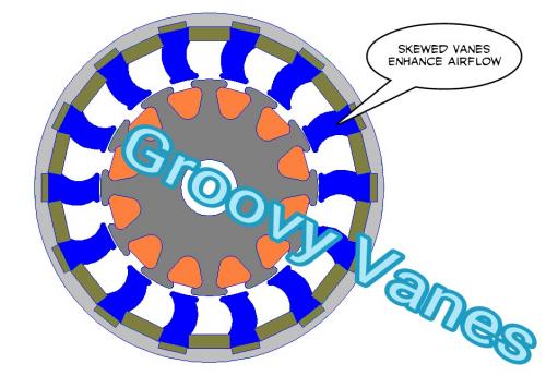
The different colors represent the flux orientation for the magnets or the phases of the coils as well as aluminum and iron pieces.
This version really slims down the magnets and pushes them even further away from the heat source which is the copper. Air circulation would be at least 10x better than a normal RC motor design, so this motor could absorb punishment well into the abusive range. For ebikes that tend to get abused this would be the way to prevent failures.
It would still run efficiently at low currents... so that's another "Win Win".
.
.
This is an afterthought... but if you look at the blue "Vanes" of the motor, if they are skewed by design then the air will be pushed sideways like a jet engine. It will literally "pump air" from side to side so external fans would not be required. Considerable airflow is possible, especially at 5000 rpm which would be considered something of a turbo effect.
.
.
There's always the guy that needs to "find the limit" on these things... so this is about as extreme as you can get. This is for the "Bad Boy" that wants the "Big Balls". (you know who you are)
At 1000 rpm -> 7 Nm * 2 * pi x 1000 rpm / 60 = 733 Watts
At 2000 rpm -> 7 Nm * 2 * pi x 2000 rpm / 60 = 1466 Watts
At 4000 rpm -> 7 Nm * 2 * pi x 4000 rpm / 60 = 2932 Watts
At 8000 rpm -> 7 Nm * 2 * pi x 8000 rpm / 60 = 5864 Watts
...air cooling is the same as before, but weight increases as does overall radius.
Figure 1 shows the model of a usual space harmonic gear with usual permanent magnet array. It consists of a high speed rotor with permanent magnetic chips at its outer surface, a stator gear with beam type poles made of soft iron and a low speed rotor in which permanent magnetic chips are pasted on its inner surface. In a surface magnet type magnetic gear, the torque is transmitted from the driver to the follower by magnetic forces. Since, the number of poles of the high speed rotor is 8 and the number of poles of the low speed rotor is 44 in this research, the gear ratio is 5.5, and the low-speed rotor is rotated in the opposite direction to the high-speed rotor.
.
.
This might be the "Holy Grail" of magnetic gear reduction with a 95% efficiency.
(something I struggled with much earlier in the thread)
.
...the hysteresis has low efficiency, so I gave up on it.
.
The PDD® machine is a pioneering extension of the low ratio magnetic gear and was invented and demonstrated by Magnomatics personnel in 2005 and is widely regarded as the most significant advancement in electrical machine design for 20 years. This ground breaking technology combines the high torque density of the magnetic gear and the functionality and performance of a brushless permanent magnet machine to offer unparalleled torque output for direct drive applications.
.
.
Basically they took it to the next level and COMBINED the magnetic gear with a motor to create the "Holy Grail" of ebike designs.
Amazing.
Gear reduction is built into the motor itself through magnets, so it's frictionless.
This product is already designated as "EV centric", so it's on track for electric cars. What is needed is an ebike version.
.


I see that you haven't understood my post.
There is no way that the solenoid can "slam" itself into the walls at the end of the stroke, because its speed is LIMITED by the clutch, and that speed is relatively slow.
With a Hall effect sensor determining the end-of-stroke position, the solenoid reverses direction and instantaneously the other clutch engages, again limiting the speed of that return stroke.
If the POSITION of the plunger is plotted against TIME on a graph, it will draw a nice triangular waveform.
The changes of direction at the end of strokes are done smoothly and silently.
Yes, with a sensor it should work.
You can know when it's time to turn the power off because the sensor let's you know what is going on.
Initially I was assuming a sensorless design (for everything) so having natural rebounding seemed the most logical way to keep things running as planned.
If the "device" has no natural limits to it's stroke then it will just keep extending.
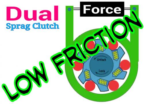
Which actually leads me to the next problem about the dual sprag clutch... "friction":
.
.
In our earlier design:
.
.
...and just ignore the "propulsion device" and focus on the Forces that are created by the two struts that connect to the levers coming off the sprag clutches.
When one is "loaded" the other is not. This is a problem.
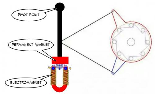
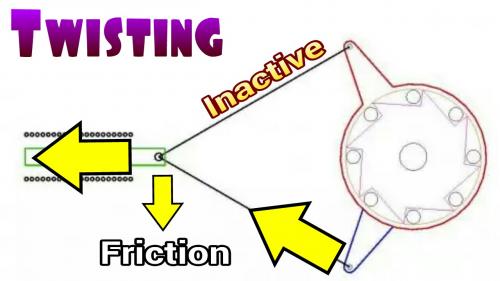
Actually this pendulum idea isn't that bad because the pivot holds the intersection point in one spot. Had this been our more solenoid like diagram then the reaction forces of one strut that is "free" and another that is "loaded" will produce a twisting torque that would cause friction, especially if the solenoid is anything like a shock absorber in mechanical design. (smooth long shaft)
.
.
The "push-pull" idea would involve the "force device" being fixed to the bike, but at least when the device operated the imbalanced forces will at least cause limited friction.
If this is the way to go then an entirely different electrical force creating "device" needs to be looked into as an alternative.
The single and dual sprag clutch designs seem to cause things to drift apart.
Single seems to go best with an "oscillator". (sine wave)
Dual seems to go best with "push-pull". (linear)
...but I will have to try out the pendulum approach in FEMM. That hasn't been simulated yet and it's the easiest to do. The "push-pull" design has a subtle problem in that you need a "floating linkage" of some sort to correct for rotation, so the pendulum might be the way to go.
.
.
Pendulum Sprag Clutch (or Leveraged Sprag Clutch)
Seems to have everything:
No friction sliding problem.
Dual sprag clutch.
Sensorless since it's a self correcting oscillator.
...even incorporates the Halbach style magnets.
.
.
This is the Single.
Such a design is mechanically less complex and has no friction at all.
The oscillator self regulates and centers itself, so sensorless operation is possible.
Power is good because of powerful Neodymium magnets in a Halbach style.
...it has a lot going for it.
.
.
This begins to really create a potential "product".
The fact that the silicon steel is now wrapped around the sprag clutch means you have the room you need for copper which means lower copper losses at the price of a little more weight, but this is very light to begin with, so we can splurge.
Very, very compact.
It might be possible to use the right side bottom bracket threads as a mount. Just pull out the stock right side cup and install one that holds the coil in place. You might need an extra brace, but that's easy to do.
.

.
Totally off this topic, but this new rim drive looks nice.
http://www.gizmag.com/velological-worlds-lightest-e-bike-drive/31976/
.
.
The 2 linkages between the solenoid and the clutches do not apply anymore.
About one week ago I described a system with only one linkage, with the 2 clutch arms placed side by side, and a small lever between the two.
Anyway, this will necessitate a reduction drive before going to the crankwheel.
The sprags direct on the crankwheel will not be powerful enough.
The 2 linkages between the solenoid and the clutches do not apply anymore.
About one week ago I described a system with only one linkage, with the 2 clutch arms placed side by side, and a small lever between the two. There is no un-aligned forces, so no friction.
Anyway, this will necessitate a reduction drive before going to the crankwheel.
The sprags direct on the crankwheel will not be powerful enough.
.
.
The truth is it's hard to know without deeper study.
The way small motors achieve impressive power is through high rpm. If you can switch rapidly and at a higher current level you produce more power. This is the basis of just about every motor, electric or gas, to simply spin faster.
So it's not a simple calculation for "power".
I know when I was rewinding the old Unite motors it took a while to get the feel of all the parameters and limitations involved. In some cases I'd so completely saturate the iron that I'd be wasting at least 50% of the energy producing nothing but heat. (which usually ended up destroying the motor)
Efficiency always seems to occur when there is a balance of all the losses... not too much current or too little or too much speed or too little. Typically the conventional motor reaches it's best overall efficiency at about 75% of it's maximum speed.
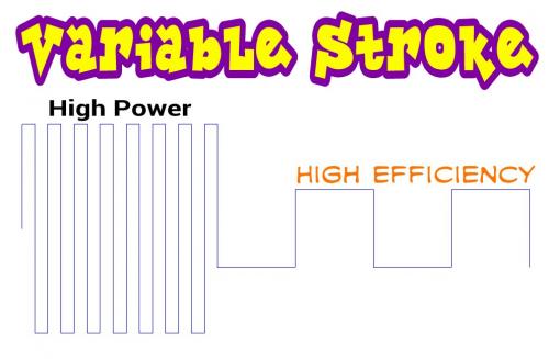
Having the option to shorten the stroke means you can blast away at higher current... which means a higher voltage (technically a higher duty cycle percentage with PWM), and since it doesn't have to go as far it can be quick.
It's still a little fuzzy to me (variable stroke length) but I think it's possible to "emulate" different gear ratios with it.
.
.
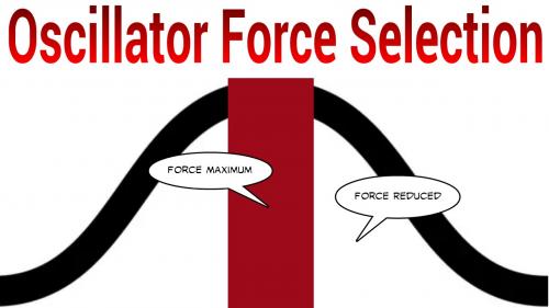
In "regular" electric motors there is a sine wave relationship of a coil and a magnet. If you were to create a Single Phase motor it would have a Force relationship with it's power such that maximum Force occurs in a narrow zone as the coil and magnet are near each other.
Three Phase (and above) motors overlap multiple "shifted" coils so that the normally sine wave relationship is smoothed out and power becomes more continuous... but ironically this trick actually means that the copper "resource pool" gets diluted and rather than having a massive peak of Force you spread it out. Obviously this depends on the design, but generally this is the case.
Linear relationships, such as a Solenoid, "can" exist, but you actually have less peak Force in those because they typically rely on a fixed air gap. Flat ended Solenoids actually allow the air gap to shrink to zero which is why they have high Force at the end, but they make lousy alternating polarity devices. (better for opening or closing something just once)
So in an oscillator it's peak Force... it's "sweet spot"... is in a narrow range in the middle.
This means if you want to exploit the full potential of the magnet-to-coil relationship you need to hit the peak MANY times per second.
Small motors actually are doing this by spinning at high rpm.
Think of the magnet as a "resource" that can be used once per second or 100 times per second. If you can use the same "resource" more often it's as though you multiplied it.
------------------
Higher efficiency can be part of the overall powerband dynamics (complex) or it can be a change in the design or behavior of the system.
Motors are often specifically designed to run best at a certain speed.
They do this by carefully adjusting the rate of current so that it matches the natural "time constant" of the motor. In a "perfect world" the current matches what the motor "wants".
So in this oscillator in "power mode" you would ram current through at higher frequency and higher current to maximize the magnets. In "efficiency mode" you lower the frequency and drop the current to just enough to deliver the minimum Force required.
.

.
Given this knowledge we ask:
"Why not increase the pole count to infinity?"
Up to a point increasing pole count is a great idea. After all, the more magnetic pole pairs you have means that the switching is taking place faster which means each magnet is being exploited more often which produces more power. A win, win.
But as some point you hit a wall... either the iron has problems with hysteresis switching so fast (heat wasted) or you simply can't get the MOSFETS in the controller to handle the insane frequencies that are required.
So we want to have the ability to increase our switching rate... but within limits.
.
.
Getting back to how one might create a "true to life" push-pull (expanding and contracting) device with magnets, I have tried many times to make one in FEMM but haven't done well.
It seems the most natural solution would involve magnets that are set up to oppose each other so that oscillation can occur between them, but they are not inclined to bang into each other.
.
.
The thinking would go that you would somehow "extract" concentrations of flux in one area creating a kind of vacuum, then flood the other zones with excess flux to create a pressure area. The "problem" is how to actually do that without having flux leak all over the place.
I have no good answer.
.
.
This is interesting...
I moved the copper coils into the center between two magnets pointed at each other.
Notice how the magnetic flux is forced to "tunnel" in between.
If this can be properly exploited so that all the energy is focused inward it looks like a possible direction to go in. Normally one would try to spin the magnetic flux outward and use a lot of silicon steel to get any power out of it.
.
At some point I need to actually go through the math...
Power = Torque * Speed
As it applies to the Sprag Clutch concept we can observe certain things:
Torque is defined as .
.
.
.
So when we look at the "root idea" cam system we see that they actually had an adjustable Torque capability because the length of the lever could be changed while in use. At present I'm not thinking of doing that, but it's there if needed.
What we can adjust is the Speed or "Angular Velocity". Since the Sprag Clutch has no set ratchet spacing and an oscillator device can vary it's stroke it's possible to change the Speed of the Sprag Clutch relative to the oscillation frequency.
As I see it you would begin by discovering the MINIMUM stroke length the Sprag Clutch is capable of while still maintaining an actual forward motion. You need this knowledge because this represents the MINIMUM oscillation stroke that can be applied when at full Power and at low Speed.
Once this minimum is known you can design the leverage so as to maximize the Radius component of Torque. This means that at maximum oscillation frequency the system overall produces the maximum power.
...which is strange.
Normally we match our maximum oscillation frequency of our "motor device" so that it exists at the maximum speed of our system. So we would be inverting the normal behavior.
Since we are already "maxed out" in our oscillation frequency and power at our lowest speed we have no way to increase speed through increased oscillation rates.
"So how do we increase speed?"
We increase speed by INCREASING the stroke length of the Sprag Clutch while DECREASING the oscillation rate. Force is created because of the "rate of change" of magnetic flux in the system ("Faradays Paradox") so if we wanted to have the same "rate of change" at lower frequency we would need to drive the currents LONGER which means more copper loss heat and likely saturation of the iron. Since this extra "waste" is not helpful we simply conceed that as the speed increases we must LOWER our expectations for the Force component. (so we actually slow the rate of current applied)
The net effect would be a system whose Torque is highest at low Speed and that Torque declines as the Speed increases. However, the current is "bound" more tightly at low Speed because under those conditions the oscillation frequency is highest. Hysteresis losses would flip and be highest at low speed as would copper losses.
On a regular PM motor they "burn up" at low Speed and low oscillation frequency, but the Hysteresis component is good at low speed and bad at high, so it's more balanced.
"Low end torque" motors do exist and one example is the Induction motor that actually works best at low speed and then fades out as speed increases.
But for a mid drive we might be able to just design for a single speed, so this option might not be required.
...not sure if I answered my own question or opened a can of worms.
.
.
At this point I need to do a review of some electric motor types.
The first permanent magnet types (which are the most common) are defined by their magnet strength. The slope of the line will match some measure of the magnet strength and stronger magnets produce more torque for the same current. In real life one doesn't typically run a permanent motor "wide open" like this because of excess heat that is created (the controller limits this) but this is the absolute torque potntial.
The second is the series motor. A field coil put in the same circuit as the "normal" coils (normal compared to a permanent magnet motor) will cause very high magnetic strength when starting out. This is sort of how I figure the Sprag Clutch idea would work because you draw more current and create more torque at low rpm than high. So the idea of an "upside down" motor does exist already.
The third motor is the shunt motor. Oddly this has a potential place in our thinking too. For a human powered bicycle the standard pedal rate is about 90 rpm. This is a fairly constant rate and good cyclists tend to keep their pedal rates between 90 - 100 rpm at all times. For a mid drive there is a strong argument that you really only want things to work well at one speed since you would be pedaling to that speed normally. This powerband resembles a "constant motor current limited" permanent magnet motor setup, which I've done a lot of testing with. The power is low at first, but it builds linearly and it "feels" satisfying because there is no disappointment as torque declines which happens with the other types. Sometimes rider satisfaction is an important criteria. (I've called it "Force Limiting" in previous threads)
--------------------
Applying this to the Sprag Clutch idea...
With the Sprag Clutch idea the maximum torque is simply a matter of how long the lever is and how powerful the magnets pull or push against each other. Beyond that it's essentially up to the designer to decide how it "behaves". It can do whatever you want it to do.
My thinking is that:
Mid Drive - Will be best served with a "constant motor current" type system because we only need to optimize for a narrow band between about 80 rpm to 110 rpm.
Direct Drive - For a direct drive configuration you want as much low end torque as you can get. This tends to push things towards high currents and torque at low speed. Since torque is interchangeable with speed, the direct drive uses excess torque to compensate for the lack of proper gearing. The Sprag Clutch has this bizarre potential to vary it's oscillation stroke which opens the door to a direct drive with a kind of variable gear ratio.
----------------
One has to ask:
"Just because you CAN, does that mean you SHOULD ?"
...and I'm not sure, variable stroke seems like a cool idea, but for a mid drive it's meaningless.
.
.
Okay so we ask:
"How much Force must my oscillator make to deliver 250 watts of power?"
For simplicity let's assume our oscillator follows a sine wave pattern and we are using a dual sprag clutch so power is being generated in both directions. We note that:
1 rad/s = 60/2π rpm exactly = 9.55 rpm approx.
So for roughly 95 rpm (desired for pedaling) we have an angular velocity of 10 rad/s.
Which means that our 250 watts divided by the 10 rad/s tells us we need 25 Nm of Torque.
"But how much Force?"
Well, that depends on the leverage involved. Let's assume we are using a lever that is 1/10 of a meter. So we get:
Torque = Force * Radius
Force = Torque / Radius
Force = 25 Nm / 0.1 m = 250 Newtons.
But we are using a sine wave...
"So how much peak Force is required?"
You take the (RMS) Root Mean Squared Force (250 Newtons) and multiply by the square root of 2 (approx 1.4) which means we require a peak Force of:
250 N * 1.4 = 350 Newtons
...so those big scary magnets aren't far from where you have to be and that's just for 250 watts.
.

.
.
So this is the point where you have to ask yourself:
"What don't I want in the design?"
I definitely don't want whatever parts are moving to have any more mass than necessary, because as an oscillator a lot of mass will create excessive vibration.
One typical line of reasoning is to have a stationary iron with copper coils and then have magnets move relative to the iron.
Another idea is to have magnets form a tight loop on their own and then pass nothing but copper between the magnets. This eliminates hysteresis entirely, but tends to have reduced heat tolerance because you can only fit a small amount of copper between magnets, so the copper is severely current limited.
Fortunately there is a better way...
You can combine the iron, the magnets and the copper coils into one stationary unit. This unit simply "switches magnetic flux" from one side to the other. In the case of an oscillator we "pull" one of the two iron "stubs" inward with a Force of 500 Newtons while only "paying" 250 Watts through the copper to achieve it.
This thought process was originated in the Lavet Motor and was duplicated and expanded upon with Parallel Path as well as others. Many patents already exist.
.

.
.

.
...so some variation of this theme seems workable as an oscillator.
The unifying charactoristic is that they all perform "flux switching" of permanent magnet flux that already exists rather than creating flux from scratch. Since copper space limitations tend to disappear (and the copper is stationary, so inertia is not an issue) we can use more copper and that lowers copper losses which usually account for most losses in the system.
We can say that technically the Sprag Clutch idea is "possible".
I'd also say that a Dual Sprag Clutch design using flux switching should be possible and if it can be completely frictionless that would be ideal. One needs to so some "origami" with the idea in order to flip things around correctly.
.
In a "normal" ebike we typically either have the very old fashioned brushed motor (mostly obsolete) or a three phase brushless motor.
In the brushed motor the controller first chops the current into pulses and then delivers the result as an unsmoothed DC output. The natural inductance of the motor smoothes out the result so that the motor is tricked into experiencing a varying current and voltage as simple DC.
In the three phase brushless motor the controller does the same chopping behavior only now you have three times as much complexity for three phases and hall effect sensors as well. The controller has to "simulate" the motor behavior and apply power as it's informed by the sensors. Sensorless operation is possible, but it's generally very poor in an ebike.
.
Okay, this is where I'm about to do some "outside the box" thinking...
"What if the motor itself acted as the inductive components of the controller?"
http://en.m.wikipedia.org/wiki/Flyback_diode
Typically a controller uses a "Flyback Diode" to either dissipate or reuse the voltage spike that occurs whenever a coil is deactivated.
There are two laws to think about:
Lenz's Law states that when you try to force current into an inductor it "pushes back" and creates a back emf.
Faraday's Law of Induction states that you only actually create a magnetic flux when the current in an inductor changes... a constant current does nothing... which is why the Faraday Paradox is what it is.
Faraday is basically saying you don't get power unless you vary current rapidly, but Lenz replies that the harder you try to push the current the more the inductor tries to inhibit you.
-----------------
So the logic of the Flyback Diode is that a coil that becomes charged and is then released of it's voltage source will have a lot of pent up energy that wants to go someplace. If you have a Flyback Diode you can either dissipate that "waste" or you can find ways to recycle it doing something useful. Without this logic the PWM controllers would never have achieved the 95% efficiencies they do.
------------------
Basically what I'm imagining here is the merging of the controller functionality into this oscillator motor concept. Since an oscillator is a very simple device with at most two inductors it seems reasonable that the Flyback Diode could be inserted into the motor itself.
An ebike where the motor and controller are truly one entity and not two!
------------------
My thinking is presently going away from permanent magnet "flux switching" (previous post) and moving towards doing the switching electronically using the Flyback Diode(s). This would permit a simplified design using just two coils and no permanent magnets.
Will eventually get to FEMM simulations.
Why do all that fancy Parallel Path stuff when a Flyback Diode does the same thing?
.
This website does a good job explaining the flyback diode:
http://www.4qdtec.com/catch.html
If you have a simple circuit with a coil:
.

.
Then it will behave like:
.

.
If you add a diode to the circuit the current will continue FORWARD, but it will now "flyback" to the entrance of the coil and form a freewheeling loop. That loop will lose momentum at a rate equal to the resistance of the loop, so if you want to dissipate energy faster you need to add a resistor. It's somewhat strange, but true that the current never reverses even when the voltage source is cut off.
.

.
What I'd want to do with two coils is "somehow" reroute the energy from one coil that has a collapsing field to the other coil that is faced with charging up it's field. This way you recycle some energy that would otherwise be discarded. At least that's how I imagine it.
If the MOSFETS are used in such a way that they are "tuned" to the oscillators inductance then the overall system should work very efficiently.
Typically the controllers are made as generic items. This would be a sort of custom controller that would be simplified and designed for a specific oscillator.
Obviously my controller circuit knowledge is minimal, so I'm just learning.
.
.
This would be a Dual Coil, Dual Sprag Clutch, with a special custom controller described previously that would allow the "flyback" diode to reroute some excess energy from the collapsing coil back into the energizing coil so as to improve overall efficiency.
No permanent magnets.
No springs.
No friction.
Since magnetic flux seeks the "path of least resistance" when the coil is activated the two iron stubs will be attracted so as to line up centered around the coil. On the opposite side of the Sprag Clutches the two iron stubs are pushed outwards which prepares them for the next cycle.
The Dual Sprag Clutches would be side by side and a very narrow air gap would exist between them so that magnetic flux would easily cross from one to the other completing a loop with the iron stubs.
In action the "free" Sprag Clutch would immediately reset as part of it's natural desire to seek the "path of least resistance", but the "power" side will demonstrate a resistance to centering that will actually create the torque.
It's all quite good... very nice...
Stroke on this will be fixed and not variable, so it's clearly better suited for a mid drive solution.
Looks to be very compact, simple, and lightweight.
.
.
http://sbfel3.ucsb.edu/6mv/undulators/hybrid_config.html
.
.
Halbach Arrays are expensive because you need more magnets. But by placing iron between magnets in a Halbach Array configuration you can get most of the benefits at a lower cost and also open some other design possibilities.
.
.
...the performance is good too.
Cooling !!!
Another big benefit for a motor design is that you are creating an air gap that would improve air circulation. The extra cooling will help the coils and protect the magnets. One might even put oil or water cooling systems in these spaces.
.
.
Kind of a simple concept.
You could create a linkage that would pivot and give Dual Sprag Clutch behavior.
This obviously has friction, but if it allows for the use of a single oscillator it might be worth it just because it's easy to do.
Could be a "first test" design.
There are probably many variations on this including leverage enhancing ones.
.
.
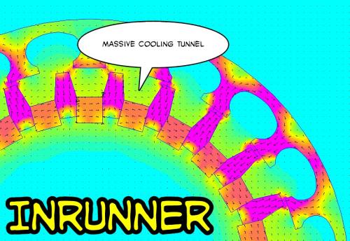
Getting back to the Halbach Arrays with Iron in them...
An Axial Flux design is possible (above) that has massive cooling tunnels to allow heat to dissipate.
But where people should get really excited is when you consider the more conventional motor designs with are either Inrunners or Outrunners. Either way you could do it, here is an Inrunner design:
.
.
This is actually very exciting because you can use about the same amount of Iron as normal, but by rotating the magnets sideways into a Halbach Array configuration you can produce the massive cooling tunnels that people dream of to allow more extreme currents.
The typical problem with direct drive ebikes is that at cruising speed you want efficiency and low currents, but every once in a while you want excessive currents and that generates a lot of heat. With this design you can abuse the motor more because the cooling is better and the magnets are also further from the hottest areas, so they are protected.
Great stuff.
With a slight skew in the Iron pieces between the magnets you create a directional airflow so you could in effect "pump air" through the hottest region inside your motor. Where normally people are obsessed with narrow air gaps (which means no room for air circulation) this introduces these massive cooling tunnels while not subtracting from the magnet strength. The magnetic flux is very high with this too since the Iron pieces act to extend the range of the magnetic flux.
All the fractional poles-to-coils math can apply too, so all the RC motor tricks are usable. (DLRK)
.
.
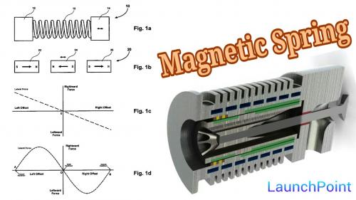
http://www.launchpnt.com/portfolio/transportation/electromechanical-valve-actuator/
The current prototype is implemented on a Rotax 500cc one-cylinder engine with a modified head. The power requirement for this particular prototype has been measured experimentally to be 56 watts at 1000 rpm and up to 278 watts at 5000 rpm. In addition to the low power requirements, the valve seats reliably at a velocity below 0.1 m/s. In order to operate robustly, the actuator and controller were designed to handle large changes in operating temperature and differences in pressure across the valve. The actuator is designed to dissipate 500 watts of waste heat at a maximum operating temperature of 392F. The controller is able to compensate for the significant changes in the actuators electrical resistance as well.
.
.
.
.
LaunchPoint has some really, really smart guys and they built a Halbach Array motor that was excellent some years back that they have now upgraded to a Version 2.0.
In short... EVERYTHING I've been thinking about in a high efficiency oscillator has been achieved with their LaunchPoint actuator. They use the "magnetic spring" concept to achieve a non-linear spring response that assists in reversing oscillation momentum. (very important)
Good job LaunchPoint !!!
One could combine one of these LaunchPoint actuators and a single Sprag Clutch and basically be "done" because the efficiency is so good that improvement would be difficult.
This is dramatically better than a solenoid.
.
.
Another thing LaunchPoint is up to is Levitation.
Again, it's the Halbach Magnet configuration that is at the core of the idea, so it seems that Halbach ideas can show up in many places.
.
.
Two opposite polarity magnets by themselves will create a force of repulsion between them, but what makes this so interesting is that as the magnets pass from side to side there is a very powerful realignment force that tends to center everything. The centering force is almost as strong as the repulsive force, so it's strong enough to keep a train from falling off it's track.
http://www.launchpnt.com/portfolio/transportation/spm-maglev/
.
.
I have to say this is some really great stuff... the Halbach Array with Iron.
Since the Iron associated with the magnets doesn't really "cycle" we can use compounds like Cobalt in the Iron which increases magnetic flux.
The air cooling capability is probably increased by 10 times over an ordinary motor.
.
.
...I noticed that the tighter the backside gets the stronger the magnetic flux.
Lot's of air spaces without sacrificing magnetic flux strength !!!
http://www.google.com.mx/patents/US7148778
.
.
...this is a way to enhance an Outrunner design.
.
.
Now we are getting into something like a RC motor design. This (above) would be designed for high rpm operation. Four magnets is the practical minimum. A 4 Pole (2 Pole Pairs) motor could use fewer slots for the coils, there are many possibilities.
.
.
The geometrical relationships seem to matter. I really haven't figured out exactly how the geometry would work best, but some are better than others.
The scale is now going all the way up to 2.0 Teslas, which is impressive.
People have gotten pretty good at optimizing the magnetic flux for a given set of magnets and iron, but they've never gone to this extent to increase cooling. For an RC motor cooling is no big deal because you don't spend much time at low rpm and high torque. For an ebike the extra cooling tunnels could be the difference between meltdown and survival.
So this is an example of design where "form follows function", for ebikes cooling really matters more than in most other applications. (so it's a unique situation seeking a unique design)
.
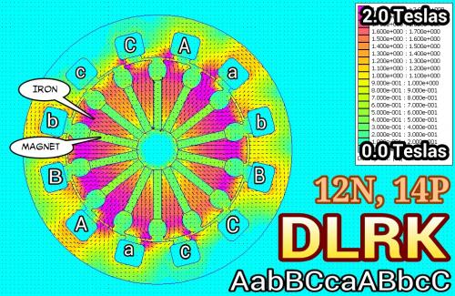
.
...normally this 12N, 14P DLRK configuration is for an Outrunner, but it seems to work as an Inrunner too. Would have to do some serious research before making one.
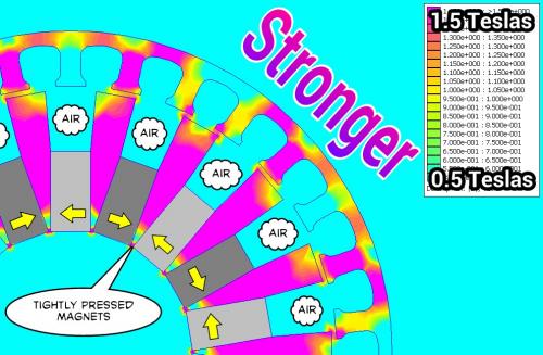
High magnetic flux (Tesla) levels are created because two opposing magnets build a sort of "sandwich" with the iron in the middle and it just squishes outward.
An important note:
The iron in the middle between the magnets NEVER oscillates... so you can afford to allow it to saturate (2.0 Teslas) and not have hysteresis losses. Only the iron on the outer ring oscillates fully.
.
.
Even the highest strength Neodymium magnets only max out at around 1.4 Teslas (BrMax) of flux strength. That means that by themselves they NEVER climb any higher.
.
.
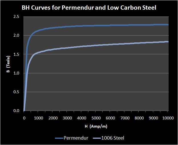
Different mixtures of steel (including mixes that involve Cobalt) can rise to 2.5 Teslas of flux but don't go there on their own and if you drive them there it will create a large Remanence (hysteresis) that will create heat if oscillating. These "Flux Sandwich" elements don't oscillate, so they will not heat excessively. (they will heat somewhat)
.
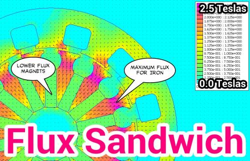
.
What makes this so interesting is the "Flux Sandwich" combines two opposing magnets of lessor flux strength and squeezes the iron so that it is "driven" to it's potential.
Overall this configuration seems to amplify each element to their maximum potential.
The air gaps are an added bonus... but the increase in flux is the most alluring feature.
A true "Win Win".
.
.
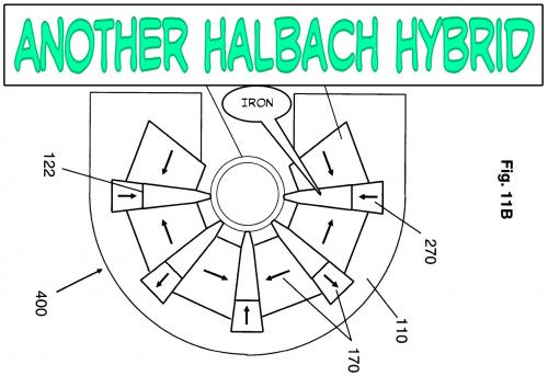
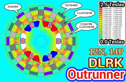
By adding a "Third Magnet" we can flip things around and produce an Inrunner design.
Magnetic flux is even better.
Really amazing flux strength... that's 2.5 Teslas in some areas... one starts to wonder if there is such a thing as having "too much" flux.
And why isn't this being done already?
It should be possible to start with a pre-existing stator from an RC motor, then go about custom building the external magnet and iron shell, that way the DIY aspect is a little easier. The magnets are all cubes of sizes that are likely easy to buy. You would need to machine the iron parts, but since there is no oscillation you might get away with simple (1020) mild steel.
...it was from this patent that I figured out the "Third Magnet".
.

.
.
If you started with the 6374 Turnigy Aerodrive RC motor as your base...
.
.
Then you build the "enhanced flux" triple magnet shell shown above.
Now for the math: (I used dimensions close to the actual 6374)
At 40 amps of current I get a Torque reading of 5.5 Nm.
Angular Momentum = 2 x pi x RPM / 60
Since Power = Torque * Angular Momentum we get:
At 1000 rpm -> 5.5 Nm * 2 * pi x 1000 rpm / 60 = 576 Watts
At 2000 rpm -> 5.5 Nm * 2 * pi x 2000 rpm / 60 = 1152 Watts
At 4000 rpm -> 5.5 Nm * 2 * pi x 4000 rpm / 60 = 2304 Watts
At 8000 rpm -> 5.5 Nm * 2 * pi x 8000 rpm / 60 = 4608 Watts
...which is good.
Losses related to all kinds of things creep in as the RPM rises, but those Power figures are probably near where you would end up. The stock motor claims numbers around 2250 Watts, so this would be a moderate improvement over that. Air cooling would be much better, so your chances of overheating your magnets declines, but the stock bearings are pitiful, so you need to build everything except the stator up from scratch.
Those main magnets are 1/4" x 1/4" x 2" as used in my imperfect simulation.
The stock magnets are 1/8" x 1/4" x 2" so you can easily see you are doubling your magnet sizes this way, but then the Third magnet at 1/8" x 3/8" x 2" increases it further still. Maybe this is "flux overkill" I'm not sure, but it clearly is a strong design for flux enhancement. The outermost shell can be aluminum because it's not used for flux manipulations anymore.
Air gaps could be reduced because the stator could be carefully smoothed to perfect roundness, then the shell with it's iron elements could be smoothed and brought into very close tolerances with the stator. Normal designs expose raw magnets to the stator and are not sandable because magnets are brittle, this would not suffer this problem. The magnets are also physically further from the copper coils, so heat is diverted away through air cooling before it reaches the magnets. Radiant (direct) heating is prevented entirely.
The Bigger Hammer
The simple way to look at it is from the "Bigger Hammer" perspective. The stronger the magnetic flux (no matter how you achieve it) the stronger you make your Torque which means you can build power at lower RPM. You can always just start with a bigger motor which automatically gives you the "Bigger Hammer", but adds a lot of weight. So the idea of "flux enhancement" through magnet amplification is a way to make a smaller motor behave more like a bigger one.
If all you needed was 1000 watts of Power you could figure ways to get it to run well at 2000 RPM which makes gearing reduction much easier.
Increasing magnetic flux strength is the same as lowering the Kv.
*** Correction: In the previous post that should be an "Outrunner". (sorry)
.
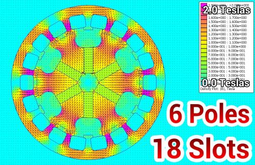
.
The different colors represent the flux orientation for the magnets or the phases of the coils as well as aluminum and iron pieces.
This version really slims down the magnets and pushes them even further away from the heat source which is the copper. Air circulation would be at least 10x better than a normal RC motor design, so this motor could absorb punishment well into the abusive range. For ebikes that tend to get abused this would be the way to prevent failures.
It would still run efficiently at low currents... so that's another "Win Win".
.
.
This is an afterthought... but if you look at the blue "Vanes" of the motor, if they are skewed by design then the air will be pushed sideways like a jet engine. It will literally "pump air" from side to side so external fans would not be required. Considerable airflow is possible, especially at 5000 rpm which would be considered something of a turbo effect.
.
.
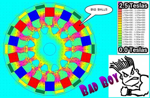
There's always the guy that needs to "find the limit" on these things... so this is about as extreme as you can get. This is for the "Bad Boy" that wants the "Big Balls". (you know who you are)
At 1000 rpm -> 7 Nm * 2 * pi x 1000 rpm / 60 = 733 Watts
At 2000 rpm -> 7 Nm * 2 * pi x 2000 rpm / 60 = 1466 Watts
At 4000 rpm -> 7 Nm * 2 * pi x 4000 rpm / 60 = 2932 Watts
At 8000 rpm -> 7 Nm * 2 * pi x 8000 rpm / 60 = 5864 Watts
...air cooling is the same as before, but weight increases as does overall radius.
.
Journal of Electromagnetic Analysis and Applications
Vol. 5 No. 6 (2013) , Article ID: 32637 , 7 pages DOI:10.4236/jemaa.2013.56039
http://file.scirp.org/Html/1-9801447_32637.htm
.
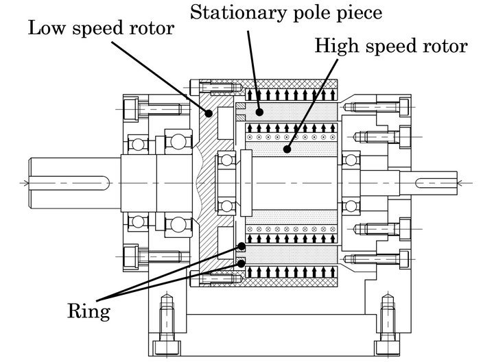
Figure 1 shows the model of a usual space harmonic gear with usual permanent magnet array. It consists of a high speed rotor with permanent magnetic chips at its outer surface, a stator gear with beam type poles made of soft iron and a low speed rotor in which permanent magnetic chips are pasted on its inner surface. In a surface magnet type magnetic gear, the torque is transmitted from the driver to the follower by magnetic forces. Since, the number of poles of the high speed rotor is 8 and the number of poles of the low speed rotor is 44 in this research, the gear ratio is 5.5, and the low-speed rotor is rotated in the opposite direction to the high-speed rotor.
.
.
This might be the "Holy Grail" of magnetic gear reduction with a 95% efficiency.
(something I struggled with much earlier in the thread)
.
...the hysteresis has low efficiency, so I gave up on it.
.
http://www.magnomatics.com
The PDD® machine is a pioneering extension of the low ratio magnetic gear and was invented and demonstrated by Magnomatics personnel in 2005 and is widely regarded as the most significant advancement in electrical machine design for 20 years. This ground breaking technology combines the high torque density of the magnetic gear and the functionality and performance of a brushless permanent magnet machine to offer unparalleled torque output for direct drive applications.
.

.
Basically they took it to the next level and COMBINED the magnetic gear with a motor to create the "Holy Grail" of ebike designs.
Amazing.
Gear reduction is built into the motor itself through magnets, so it's frictionless.
This product is already designated as "EV centric", so it's on track for electric cars. What is needed is an ebike version.
.
Pages