*** Disclaimer: At this point I'm excited about the magnetic gearing concept, but don't understand all the harmonics involved. Take this as a beginners mind vision of what is possible.
Taking the Turnigy 6374 Aerodrive as a base (stationary) you could wrap that base with a rotating shell of Iron spaced at a correct harmonic relative to the base. Then on the outside you have another harmonic that is relative to the other two and it has many magnets.
The gear ratio becomes the outer ring divided by the inner stator.
--------------
With DLRK you will have something like a 12N stator and a 14P set of magnets. This means that if you divide the magnets in half you have 7 magnets per half compared to 6 stator elements... that's one extra per half. By that logic one might "guess":
12N --> ( 6 + 1 ) * 2 = 14
12N --> ( 6 + 2 ) * 2 = 16
12N --> ( 6 + 3 ) * 2 = 18
...but there are other harmonics like with dividing the 12 by 3 or by 4, so it gets very involved. Knowing which harmonics work best will take some research.
What's really great about all of this is that you can in effect build the gear reduction into the internals of the motor itself, which has been a kind of "Holy Grail" of ebikes since the beginning.
------------
Doubt
I'm already becoming a little doubtful of using this magnetic gearing idea inside the motor. The most critical thing in most motors is the air gap. Larger air gaps tend to diminish performance and in these magnetic gearing motors you tend to have two (or more) air gaps.
As a magnetic gear alone you can argue that it's a comparison between a friction based interaction of metal on metal verses a magnetic interaction... so you can claim some small benefit. (1% to 2%)
A big plus is that magnetic gearing should be really quiet and never wear out and those features might be the stronger arguments.
And there's always just the idea of using a higher pole count motor to begin with which reduces motor rpm anyway. If you are using all those magnets on the outer ring you might as well build a stator with a near equal number of elements.
...so unlike the addition of the "Halbach Hybrid" idea discussed previously which is "pure improvement" I'm not entirely sure if having two air gaps is a good direction to go.
You could combine the "Halbach Hybrid" ideas into the "Magnetic Gearing Motor" idea to make things better, but the added air gap is still a problem.
Separating the "motor" and the "gears" by using magnets makes some sense.
If you had a motor that ran optimally at 6000 rpm, but a maximum output desired of around 100 rpm you have a 60-to-1 gear reduction requirement.
But if you could make the first stage be magnetic and you could gear it down by 6-to-1 on that first stage now all you have is a gear reduction of 10-to-1 left to complete which is easier to do with chains and sprockets.
So maybe a "two stage" solution with magnets first, then mechanical second is the way to go.
This will reduce the noise level and also eliminate the primary failure point which is usually the high speed gear. Also, since magnetic gearing has built in torque limiting it lowers the chances that the motor can become overloaded and overheated. A motor only builds heat on a "load" no matter what speed it spins, so if you have a torque limitation built in you are in esssence helping the controller control current automatically.
.
.
My understanding is that the higher the gear reduction goes the lower the torque goes (because magnetic flux gets diluted as it's redirected through the vanes) so a small first reduction followed by a larger second makes sense because it allows more torque to go through.
- High Precision : Due to the absence of mechanical interaction, the gear delivers constant precision in both low and high load cycles.
- Abrasion Free : As it is friction free, the gear performs consistently without lubrication.
- Overload Friendly : At overload the magnetic transmission acts naturally as a clutch, but remains fully functional. The elasticity causes a reduction in the natural frequency of the entire drive system, avoiding unnecessary stress to related components.
- Torque Measuring : By exploiting the inherent elasticity, the torque in magnetic gears can be easily and inexpensively measured.
- Highly Efficient : Magnetic gearboxes offer highly economical energy transfer. Energy conversion is practically seamless: losses via rolling friction and low magnetic hysteresis phenomena are minimal in operation.
- High Torque Capability : The magnetic wobble mechanism takes advantage of a constant air gap over the entire active area which makes it superior to other magnetic concepts. The result is a compact design with maximized torque.
- Scaleability : Magnetic gears, like toothed gears, are scalable. They are suited for both high and low torque operation. As the relationship between size and maximum torque transmission is cubic in nature, a gear twice as large supports up to eight times higher torque, making the gear applicable to a wide range of industries.
- High Transmission Ratio : Due to the unique concept of wobbling gears, only one gear stage is necessary to achieve high transmission ratios.
---------------
So maybe a 60-to-1 gear reduction is possible with magnetic gears. It might be expensive because it would involve a lot of magnets, but it could be possible... at least this is what is being said.
This first design has two sets of magnets and two sets of electrical copper coils that appear to be fixed. Then between these fixed elements rotates an iron ring that actually delivers output. I believe this is capable of functioning as a stand alone motor, but it also could function as just a variable speed transmission. (not sure)
This second design also comes from Magnomatics and appears designed exclusively as a variable speed transmission. This one has so many air gaps it's hard to count, but could work if you used enough magnets in order to compensate for those gaps. A motor / generator on the output feeds electrical energy back to the device in order to control gearing.
------------------
The "bottom line" is that variable speed transmissions are possible using magnets and this may be valuable for improved hub motor designs. For a mid drive a fixed ratio seems adequate.
The first thing was to check to get an idea how much torque the configuration can handle and it seems somewhere between 5 Nm and 8 Nm is possible. The later design increased torque over the "stock" patent.
.
.
If you had an RC motor that was spinning at 6000 rpm and the maximum torque through the magnetic gearing is 6 Nm then:
Angular Momentum = 2 x pi x RPM / 60
Since Power = Torque * Angular Momentum we get:
At 6000 rpm -> 6 Nm * 2 * pi x 6000 rpm / 60 = 3770 Watts
---------------
3770 Watts is 5 horsepower !!!
That little magnet could be enough for an ebike and this gives a first stage 5-to-1 gear reduction without friction and with zero noise or maintenance.
You would still need a mechanical second stage gear reduction, but you are dealing with not much more than 1000 rpm at this point and that's easier to work with. RC motors would be less likely to fail as sensorless motors because the built in torque limiting of the magnetic gearing will simply allow an overloaded motor to skip. It's like an "overload clutch" which slips if too much current is being run through the motor trying to tackle the load. Rather than forcing the controller (or the very primitive ESC's) to handle it electronically the magnetic gearing does it for you.
That patent was from 1968. (3,378,710)
Later designs improved upon this patent, but also made things more complex. This is probably the best design for a diametrically magnetized ring magnet that can be purchased for $23.
--------------------
How to understand magnetic gearing?
I see it as two waves in parallel where one has a longer wavelength than the other. If the waves line up just right they create a "surfing" situation where there is always a forward moving "preferred" path of least resistance. But just like with surfing if you fall behind the wave you lose your "torque" and have to try to catch the next one that comes along. Whenever a magnetic gear exceeds it's torque limit you fall behind to the next wave, then the next and so on which basically is like a slipping clutch.
Basically the Cycloidal Magnetic Gear is one slightly "eccentric" circle of magnets of lessor number rotating within another circle of magnets with sligtly more magnets. The difference is so small between them that the net rotation is a very small fraction of the input speed.
The problem with this idea is that you introduce a vibration because of the "eccentric" path of the inner circle, so some serious counter balancing needs to be done. You basically need the same kind of counterweight as a pisten driven crankshaft.
Otherwise it's a great idea... gear reduction of 26 to 1 is amazing.
An RC motor running at 6000 rpm would need to be extremely well counter balanced or the vibrations would be excessive. (would make for a fun challenge)
There are some slighly weird bearing interactions that need to be included and that introduces some friction. Not a major issue, but it does complicate things.
.
...as it turns out there is a patent from 2008 that took a standard 12 pole stator and added fixed pieces and then put an Outrunner shell on the outside.
.
.
I improved on the design slightly by "going Halbach" with the magnets on the outer shell in order to increase performance, but the stock configuration would be good too. Since there are fixed stator "extensions" there are large air cooling tunnels, so cooling will be very good anyway, but you add extra circulation going down the halbach hybrid route.
Features:
44 Outside Magnetic Poles
26 Fixed Stator "Extensions"
12 Pole Standard Turnigy 6374 Motor Stator
Effective Gear Ratio -> 44 / 12 = 3.667
-------------
So a 6000 rpm motor that was reconfigured this way should behave like it was going at 3.667 times a slower speed or about 1600 rpm.
Take that 1600 rpm and run it through a 5-to-1 magnetic gear reduction and you get a final output of around 300 rpm.
From 300 rpm you can easily do a mechanical gear reduction of 3-to-1 and get to the 100 rpm you need for a mid drive.
--------------
This is very impressive. You basically get a full powered RC motor that through clever use of magnets is "tamed" and made quiet and reliable.
A motor like this in a mid drive would last forever.
Actually... I'm finding many ideas for Cycloidal Drives online.
The biggest negative seems to be that if the output feeds back into one of these that the system sort of jams up because it does like working in reverse, but for a mid drive which is going to need a freewheel anyway that's not an issue.
.
.
The Dual Rotor Cycloidal Gear Reducer "solves" the vibration issue (for the most part) because the two rotors run opposite each other.
With decent bearings on all the surfaces this looks good:
.
.
...I've even seen triple rotor designs that would reduce vibration even more, but then we are getting into some serious complexity.
This category of "gear reducer" is pretty large and given all the problems ebikes have had with unreliable gear reduction it seems that a very durable concept like this could really help and allow the smaller motors to run free.
Something "more perfect" like magnetic gear reduction seems preferred, but not absolutely required. It would be interesting to see a mid drive developed with a cycloidal gear reducer.
.
I have seen people on the internet get confused about the usage of the word "Cycloidal".
The earliest gears were cut something like this:
.
.
...this was called a "Cycloidal Gear" because the teeth were cut in such a way that the contact was such that rounded edges touched other rounded edges and a lot of friction occurred. This teeth cutting style has become obsolete and was replaced by:
.
.
...which is called an "Involute Gear". The "Involute Gear" shapes it's surfaces so there is almost no slip between gear teeth and that means friction is very low.
Finally we get the last concept:
.
.
...which is called the "Cycloidal Drive" which is basically a separate category that has a variety of implementations.
"Cycloidal Gears" and "Cycloidal Drives" just don't have anything to do with each other.
The single stage "Cycloidal Drive" can have a 93% efficiency. This compares favorably with a single stage of chain and sprockets, but since on a mid drive we often see multiple gear reduction stages you have to add them up.
Stage 1: 95%
Stage 2: 95%
...overall you get 90% efficiency with a two stage reduction, so the "Cycloidal Drive" can actually have LESS friction.
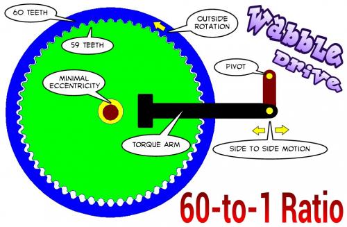
The guy calls it a "Wabble Drive" and for the moment I'll go with his terminology.
.
.
What is interesting is that higher gear reduction ratios actually translate into LESS vibration because the relative difference between inner and outer teeth numbers is less.
You could also (possibly) move the orbital bearings to the outside.
Drive this one with the bearing to the right and have the left two fixed.
.
.
...this one is "only" 40-to-1. :)
By moving the bearings outside it allows the gears to become smaller. The output is now in the center which allows for a single durable bearing there.
Not sure if driving one will actually get the other two to follow along. In a three dimensional design you could link all three bearings as they normally do with a single driveshaft which would definitely work.
Smaller gears with larger tooth counts (that are wider) will reduce eccentricity and vibration, so there is a strong incentive to push the bearings outside the gears.
.
The eccentric bearing would be "behind" and the outer gear would extend over the top of the inner gear. Then the outer gear has a torque arm which would have a linkage to give it some freedom of movement.
The output gear probably would need it's bearing as if coming out from the animation.
Really need to do this in AutoCAD. (I'm in FEMM)
Same 40-to-1 gear reduction.
Less mass to get oscillating and fewer bearings... just two major bearings and two pivots.
-------------------
Having gone past 250 posts on this topic it's amazing how a fresh new idea comes in... actually there have been several new influences lately.
This could really seriously permit high rpm motors to run at high enough speeds and still be able to get enough gear reduction to drop those speeds to something reasonable.
With a little finesse in the counter balancing it could operate smoothly.
-----------------
Don't forget that you cannot operate this without an additional freewheel. This type of device cannot be run backwards (regen) and would make no sense as part of a hub motor.
I'm still toying with a sprag / ratchet / cycloidal design, but my mind sort of explodes on how to do it. One day maybe. ;)
.
How about putting a solenoid on the arm and oscillating the outer ring which would then rotate the inner ring. This would allow a high frequency short stroke solenoid to rotate a wheel without the use of a cam and gear down several thousand strokes per second to a few hundred rpm. There may be some difficulty getting constant coordinated contact between the central sprocket and the eccentric ring.
With a hammer, a chisle can be made. With a hammer and chistle, files can be made. With hammer, chisle, and file anything else can be made.
Kaishan k500w retired, Merida TEV500 on indefinite sabbatical, currently using a Currie E-zip Trailz.
My mind is filled with so many ideas related to this that I'm having troubles filtering it all down to a single direction to go in.
The idea of using an oscillator instead of a rotating motor is good because with the cycloidal gear we are "already" vibrating... why not just merge the two? (your point)
Called a "Hypocycloid" or a "Two Stage Cycloidal" this can reduce by a combination of two concurrent cycloidal gears at the same time creating an incomprehensible reduction in a compact package.
.
.
This particular reduction unit has a 100-to-1 ratio.
The trick is that the two gears "handshake" each other and that eliminates the need for a torque arm. Power comes in the input and goes out the output without the need for an external torque arm or the need for spinning needle bearings in an internal shaft. (no positional shafts required)
.
.
The two cycloidal gears are of slighlty different sizes, but close enough to largely balance out each others vibrations. There would be some vibration, but not much... and gear reduction is so high that you are capable of using extremely high rpm motors which maximizes the magnets in them. High speed tends to translate to high power-to-weight ratios.
These are the two gearsets for the Hypocycloid mentioned previously.
Notice that one spins (the outside ring) faster than the other, but the input is the same.
Since each independent gearset acts in a "handshake" with the other where when one is "active" the other is "floating" they will tend to reposition themselves so as to advance the outer ring more slowly.
The phrase:
"One step forwards, two steps back."
...comes to mind, only in this case it's:
"8/7 step forward, then back up by 6/7 of that." (net result 1/49)
Not sure if all my geometries are correct. (should the gearsets be eccentric relative to each other or should they be aligned in phase or out of phase?)
One gearset acts as the "torque arm" of the other.
Update:
This is a real "no-brainer". The first gearset outer ring is attached to a base (attached to the frame) and the second gearset outer ring runs independently and provides output. It's a simple matter of two gearsets with differing ratios making up a combined output. It's not complicated at all.
Looking at the animations above the output is the "relative difference" in induced rotation speeds of the two gearsets.
Check it out... this is NOT rocket science...
.
A very easy way to get significant gear reduction with high reliability and requiring very little volume. (for an ebike this could be about 1" in diameter)
Commentary
We are all going to look back to the days when mid drives were using multistage gear reduction and probably laugh at how bulky and unreliable they were. This Hypocycloid Reducer seems capable of giving as much gear reduction as we require (which is about 50-to-1) and it does so with minimal effort.
I'm shocked... were we all this dumb? How was this missed?
Would work great on an ebike as part of a mid drive. (requires additional freewheel)
.
.
This animation is somewhat abstract... but it starts from a zero aligned position and goes through one revolution of the outer gearset and that translates into very little movement on the inner gearset.
The brown dot moves very little.
(it was a lot of work just to produce 9 frames of animation)
It should at least clear your mind on the logic of how it works... it's very simple.
.
It should be easy enough to build into the eccentric shaft an extra counterweight that will balance out the oscillations of the gears.
I've heard that it might require some "out of phase" adjustments because the rotation of these gearsets is not in simple circles. (they are hypocycloids)
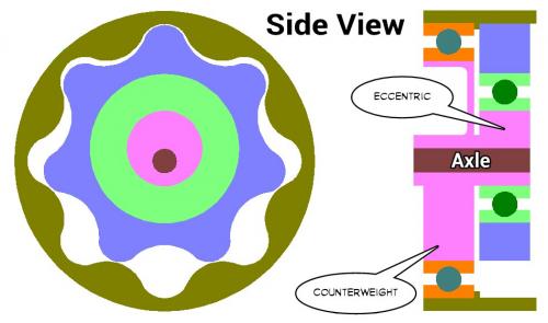
You can either increase the size of the main bearing and place the Counterweight inside or you can place it on the side.
Another idea would be to have a true "crankshaft" with Counterweights on each side. Since the Two Stage Hypocycloid Reducer has "gears" of different sizes I could imagine two separate weights on either side that compensated exactly for the gear on each side. If done properly you could have almost no vibration even when the motor is spinning at 5000 rpm or above.
.
.
A Side View of the idea of using the larger outside bearing.
Notice how this makes the design more compact over having the Counterweight external to the bearing.
R1 = Average radius of the two eccentric gears.
L1 = Combined width (thickness) of the two eccentric gears.
M1 = Total mass of the two eccentric gears.
I1 = Moment of inertia of the two eccentric gears. (pre-eccentric)
Half Cylinder:
R2 = Radius of the counterweight.
L2 = Width (thickness) of the counterweight.
M2 = Total mass of the counterweight.
I2 = Moment of inertia of the counterweight.
Other Variables:
D = Density of steel. (same for gears and counterweight)
E = Radius of eccentricity of the two eccentric gears.
IE = Moment of inertia of the two eccentric gears. (post-eccentric)
I2 = ( (1/2) - (16/(9 * (Pi)^2)) ) * (1/2) * Pi * (R2)^4 * L2 * D
-----------------
By the Parallel Axis Theorem we get:
Eccentric Moment of Inertia = (Moment of Inertia) + ((Mass) * (Eccentricity)^2)
IE = I1 + ( M1 * (E)^2 )
-----------------
Since the eccentricity of the two gears "creates" the imbalance we want our counterweight to exactly equal the moment of inertia of these two eccentric gears:
.
IE = I2
.
IE = I1 + ( M1 * (E)^2 )
IE = ( (1/2) * Pi * (R1)^4 * L1 * D ) + ( ( Pi * (R1)^2 * L1 * D ) * (E)^2 )
.
I2 = ( (1/2) - (16/(9 * (Pi)^2)) ) * (1/2) * Pi * (R2)^4 * L2 * D
.
Now let's combine the two equations and isolate the eccentricity (E):
.
( (1/2) * Pi * (R1)^4 * L1 * D ) +
( ( Pi * (R1)^2 * L1 * D ) * (E)^2 ) =
.
( ( (1/2) - (16/(9 * (Pi)^2)) ) * (1/2) * Pi * (R2)^4 * L2 * D )
.
Subtracting:
.
( Pi * (R1)^2 * L1 * D * (E)^2 ) =
.
( ( (1/2) - (16/(9 * (Pi)^2)) ) * (1/2) * Pi * (R2)^4 * L2 * D ) -
( (1/2) * Pi * (R1)^4 * L1 * D )
.
Now we see we can remove Pi and D from each part of the equation:
.
Okay, now that's nasty enough that I need to go back and confirm that it's valid (or reasonable) by plugging in some numbers. Will do later.
There are a total of five variables (R1, L1, R2, L2, E) that interact with each other so the equations might need to be redone in order to solve for a desired outome. R2 is the radius of the counterweight, so that might be a good equation to have.
.
Plugging these formulas into a spreadsheet is a no-brainer.
I wouldn't bother too much with deriving the pure math equation when you can use a computer to do the math. I just defined the variables in the spreadsheet and then you can manipulate the entire messy equation as a stand alone entity.
Anyway... seems that you need a considerable counterweight to balance a hypocycloid reducer.
The idea of squeezing the counterweight inside a large bearing is not likely going to be enough.
.
I - input speed
O - output speed
a - first (or input) stage ratio
b - second (or output) stage ratio
.
So what's interesting is that in the chart the YELLOW gear ratios are what you think they would be, but outside those combinations it gets very weird.
Just be careful to realize that this is a fractional relationship. Closer ratios of the gearsets will have the highest output ratios, but as they diverge the output ratios go DOWN which is counter intuitive.
It's not as simple as multiplying the ratios together !!!
I was fiddling with the spreadsheet and looking at the numbers and I believe I made an assumption that was incorrect.
Why would the ENTIRE eccentric gear mass need to be balanced?
Wouldn't you only need to discover the difference between the centered gear mass and the eccentric mass?
If this is the case (and it seems "more intuitive" that it would be) then the counterweight only needs to be big enough to adjust for the eccentricity induced vibration.
.
.
Assuming this is true, then the use of a big bearing makes sense and it would make for a very compact design.
In this example the counterweight is about 1/10 the weight of the gears.
.
.
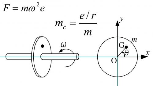
I did a little more research about eccentricity balancing. The Force of the vibration is defined by the mass times the angular velocity squared times the eccentricity dimension. The balancing mass (Mc) can be at any distance from the center of rotation (r) and that determines how much you need. The longer the counterweight is from the center of rotation the smaller that counterweight can be because e/r where e is the eccentricity of the unbalanced mass.
So it's a ratio... the larger the eccentricity, then the larger the percentage of the eccentric gears that will create an unbalanced condition. But with small eccentricity you will have a small percentage of the eccentric gear mass that needs balancing. You would not equal or exceed 100% until the eccentricity extended beyond the edge of the gears. (which would never happen)
As for the counterweight... there is no fixed weight definition because the distance that the weight is from the center of rotation determines it's apparent mass.
General Guidelines:
Make the eccentricity of the gears as small as possible.
Make the radius of the counterweight as large as possible so that you can reduce it's mass to a level that balances the system.
Apply the formulas using a spreadsheet because it's easier than working out the math in full.
Expect all situations to have a customized solution.
Many things about the Hypocycloid Reducer defy your common sense.
One interesting thing is looking at the relationship between the size of the gears that will rotate in an eccentric manner and what kind of vibration will result.
It's obvious that as eccentricity increases that vibration will also increase, but since the formula for the increased moment of inertia reduces to:
Vibration = ( Mass of Gear ) * Eccentricity * Eccentricity
Anyone who ever took an old Sturmey Archer three speed apart would have seen an example of "Compound Planetary Gears".
The negative is that you have the extra planetary gears (which might be fragile) but the positive is that you get the same high gear reductions with better efficiency.
Since you are using conventional gear tooth geometries you can use Involute gears which make sure the teeth aren't sliding against each other creating friction.
.
.
During World War II, a special variation of epicyclic gearing was developed for portable radar gear, where a very high reduction ratio in a small package was needed. This had two outer annular gears, each half the thickness of the other gears. One of these two annular gears was held fixed and had one tooth fewer than did the other. Therefore, several turns of the "sun" gear made the "planet" gears complete a single revolution, which in turn made the rotating annular gear rotate by a single tooth.
------------------
More than anything else the biggest advantage is that "Compound Planetary Gears" have a symmetric geometry which means they are naturally balanced. No need for a counterweight !!!
So "old school" might actually be better or at least easier to make vibration free.
The thinking is that the gear itself takes the place of a bearing so that a planetary gear configuration has fewer breakable parts.
.
.
By placing an electric motor in the middle you now have the dual stage "fractional" gear reduction with very high reduction rates but without as much friction.
--------------
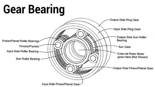
Precise control: Rifle-true anti-backlash produces a planetary transmission with zero backlash, resulting in smoother operation and superior control.
Improved thrust bearing: Gear teeth design give superior thrust bearing performance.
Unprecedented speed reduction: Through phase tuning, a one-tooth difference between ground and output rings is possible, creating opportunities for significant reduction ratios at both low and high speeds (from 0.5:1 to >2,000:1).
Less noise and vibration: More evenly distributed planet loading reduces cyclic loading and rough spots, reducing noise and vibration.
Low cost, simple design: Gear bearings combine gear and bearing functions to reduce materials and cost, while also reducing weight and simplifying the design.
High strength: Gear bearings are more structurally rigid and provide higher overall load capacity compared to fixed planetary designs.
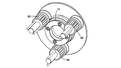
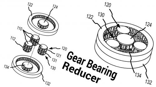
In this reducer the center gears spin. Both center gears (124, 134) are actually fixed together even though they are represented as separate in one view. One external ring would be fixed and be considered the input side. The other external ring would be the output side.
The planetary gears would spin freely... causing no output... if the gear ratios were the same on both input and output.
But if the output gears have just one less tooth than the input gears then the output would be a small fraction (one tooth relative to tooth total) compared to the input. The planetary gears spin like crazy, but the output just crawls along !!!
Note that the gear bearings are supported by a ring on the outside edges. This ring acts as the bearing surface and the gear bearing rolls on it like a roller bearing. This is the essential idea of the gear bearing.
.
.
The final step is to insert an electric motor inside one of these reducers. However, one wonders if this last step is necessary and would depend on the configuration you are seeking. For an ebike I can see the "inside motor" design as favorable because it narrows the system overall, but as weight is concerned a more compact external reducer might be better.
There are other very bizarre things about the gear ratios where weird combinations of planetary vs inner vs outer gears create insanely large gear reductions. I need to study that math some more.
Education:
B.S., military science,
U.S. Military Academy at West Point;
M.S. electrical engineering,
The George Washington University
Born: Brainerd, Minnesota
...like Klaus Halbach his work may benefit ebikes and deserves mention.
The gear bearing reducer seems perfect for a lightweight gear reduction to transfer power from a high speed small motor to a middrive, a reduction of about 50-to-1.
At present it seems that middrives are using conventional gear reduction strategies that are rather bulky.
His most recent patent (2012) uses planetary gears to create a variable speed transmission which has always been the "Holy Grail" of gear reduction.
From the patent:
This invention is the result of nearly twenty years of periodic efforts by John M. Vranish to find a way to get continuously variable performance from a geared two-stage planetary transmission. The initial work began around 1995 with the first failed attempt and received renewed emphasis in 2005 when John M. Vranish developed two-stage epicyclical planetary gear-bearing transmissions for precision positioning telescopes in NASA applications. The work attracted interest from the NASA commercialization group and efforts turned to finding a way to turn this concept into a continuously variable planetary transmission. The search for a geared CVPT failed repeatedly. Each new approach failed for one of three reasons. 1. The concept violated the “Tooth Count Dilemma”. That is, continuously variable shifting requires the ground ring gear to add teeth to retain proper mesh. 2. Solutions that provided a way around the “Tooth Count Problem,” didn't shift. The Ground gear teeth could move along the planets, but the output would not change. 3. Designs that used moveable grounds shifted speeds at the output, but did not provide mechanical advantage. Also these moveable grounds required extra energy and were wasteful.
---------------
I've attempted to understand the SGGT, but haven't figured it out yet.
.
The gear bearing drive, or GBD, as the team's unique actuator is called, consists of a motor embedded directly inside the gear transmission, allowing for cheaper, lighter, and stronger functioning. The GBD is a compact mechanism with two key abilities. It operates as an actuator providing torque and as a joint providing support. Back in 2006, Mavroidis and then graduate student Brian Weinberg developed the idea in collaboration with John Vranish, a NASA Goddard Space Flight Center engineer.
Elias Brassitos, a doctoral candidate in Mavroidis' lab, will use funding from a Space Technology Research Fellowship to develop the GBD for use on the Mars Rover. "For space applications, everything needs to be lighter and stronger," said Brassitos, who noted that the device would replace the entire joint assembly for the rover's manipulator, the arm that extends outside the vehicle to collect rock samples and other things
"Mobile Robotics, particularly the use of rovers as part of a wider NASA exploration strategy, puts pressures on actuation technology," said Brett Kennedy, supervisor of the Robotic Vehicles and Manipulators Group at the Jet Propulsion Laboratory in Pasadena, Calif. "We are always looking for ways to pack more torque, more power, and more functions into smaller packages," added Kennedy, who has high hopes that the GBD will help them do just that.
First, Brassitos must design various GBD architectures, each of which might be good for different applications. He'll design and build a prototype at Northeastern, and then assemble and test the device at the JPL.
While Brassitos works to develop the GBD for space, another graduate student will work to "commercialize it for earth."


*** Disclaimer: At this point I'm excited about the magnetic gearing concept, but don't understand all the harmonics involved. Take this as a beginners mind vision of what is possible.
Taking the Turnigy 6374 Aerodrive as a base (stationary) you could wrap that base with a rotating shell of Iron spaced at a correct harmonic relative to the base. Then on the outside you have another harmonic that is relative to the other two and it has many magnets.
The gear ratio becomes the outer ring divided by the inner stator.
--------------
With DLRK you will have something like a 12N stator and a 14P set of magnets. This means that if you divide the magnets in half you have 7 magnets per half compared to 6 stator elements... that's one extra per half. By that logic one might "guess":
12N --> ( 6 + 1 ) * 2 = 14
12N --> ( 6 + 2 ) * 2 = 16
12N --> ( 6 + 3 ) * 2 = 18
...but there are other harmonics like with dividing the 12 by 3 or by 4, so it gets very involved. Knowing which harmonics work best will take some research.
What's really great about all of this is that you can in effect build the gear reduction into the internals of the motor itself, which has been a kind of "Holy Grail" of ebikes since the beginning.
------------
Doubt
I'm already becoming a little doubtful of using this magnetic gearing idea inside the motor. The most critical thing in most motors is the air gap. Larger air gaps tend to diminish performance and in these magnetic gearing motors you tend to have two (or more) air gaps.
As a magnetic gear alone you can argue that it's a comparison between a friction based interaction of metal on metal verses a magnetic interaction... so you can claim some small benefit. (1% to 2%)
A big plus is that magnetic gearing should be really quiet and never wear out and those features might be the stronger arguments.
And there's always just the idea of using a higher pole count motor to begin with which reduces motor rpm anyway. If you are using all those magnets on the outer ring you might as well build a stator with a near equal number of elements.
...so unlike the addition of the "Halbach Hybrid" idea discussed previously which is "pure improvement" I'm not entirely sure if having two air gaps is a good direction to go.
You could combine the "Halbach Hybrid" ideas into the "Magnetic Gearing Motor" idea to make things better, but the added air gap is still a problem.
Hmmmmmmm.
.
.
Separating the "motor" and the "gears" by using magnets makes some sense.
If you had a motor that ran optimally at 6000 rpm, but a maximum output desired of around 100 rpm you have a 60-to-1 gear reduction requirement.
But if you could make the first stage be magnetic and you could gear it down by 6-to-1 on that first stage now all you have is a gear reduction of 10-to-1 left to complete which is easier to do with chains and sprockets.
So maybe a "two stage" solution with magnets first, then mechanical second is the way to go.
This will reduce the noise level and also eliminate the primary failure point which is usually the high speed gear. Also, since magnetic gearing has built in torque limiting it lowers the chances that the motor can become overloaded and overheated. A motor only builds heat on a "load" no matter what speed it spins, so if you have a torque limitation built in you are in esssence helping the controller control current automatically.
.

.
My understanding is that the higher the gear reduction goes the lower the torque goes (because magnetic flux gets diluted as it's redirected through the vanes) so a small first reduction followed by a larger second makes sense because it allows more torque to go through.
.

.
...however:
http://www.rejlek.at/en/Group/Magnetic-Gear-The-Invention/Magnetic-Gear-The-Invention
- High Precision : Due to the absence of mechanical interaction, the gear delivers constant precision in both low and high load cycles.
- Abrasion Free : As it is friction free, the gear performs consistently without lubrication.
- Overload Friendly : At overload the magnetic transmission acts naturally as a clutch, but remains fully functional. The elasticity causes a reduction in the natural frequency of the entire drive system, avoiding unnecessary stress to related components.
- Torque Measuring : By exploiting the inherent elasticity, the torque in magnetic gears can be easily and inexpensively measured.
- Highly Efficient : Magnetic gearboxes offer highly economical energy transfer. Energy conversion is practically seamless: losses via rolling friction and low magnetic hysteresis phenomena are minimal in operation.
- High Torque Capability : The magnetic wobble mechanism takes advantage of a constant air gap over the entire active area which makes it superior to other magnetic concepts. The result is a compact design with maximized torque.
- Scaleability : Magnetic gears, like toothed gears, are scalable. They are suited for both high and low torque operation. As the relationship between size and maximum torque transmission is cubic in nature, a gear twice as large supports up to eight times higher torque, making the gear applicable to a wide range of industries.
- High Transmission Ratio : Due to the unique concept of wobbling gears, only one gear stage is necessary to achieve high transmission ratios.
---------------
So maybe a 60-to-1 gear reduction is possible with magnetic gears. It might be expensive because it would involve a lot of magnets, but it could be possible... at least this is what is being said.
.
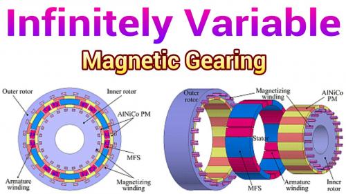
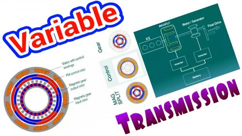
Up to this point I was studying "fixed gear" magnetic gears as well as "fixed gear" magnetic gear motors.
The next step is to have a "variable gear" design:
.
.
http://www.mdpi.com/1996-1073/7/3/1539
This first design has two sets of magnets and two sets of electrical copper coils that appear to be fixed. Then between these fixed elements rotates an iron ring that actually delivers output. I believe this is capable of functioning as a stand alone motor, but it also could function as just a variable speed transmission. (not sure)
.
.
http://www.greencarcongress.com/2014/02/20140212-magnomatics.html
This second design also comes from Magnomatics and appears designed exclusively as a variable speed transmission. This one has so many air gaps it's hard to count, but could work if you used enough magnets in order to compensate for those gaps. A motor / generator on the output feeds electrical energy back to the device in order to control gearing.
------------------
The "bottom line" is that variable speed transmissions are possible using magnets and this may be valuable for improved hub motor designs. For a mid drive a fixed ratio seems adequate.
.
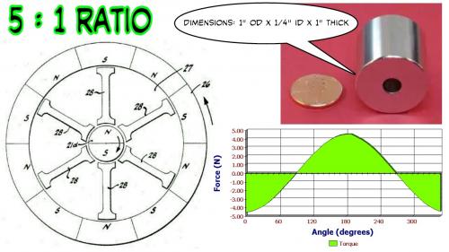
Starting with a diametrically magnetized ring magnet here:
http://www.kjmagnetics.com/proddetail.asp?prod=RX04X0DIA
.
.
The first thing was to check to get an idea how much torque the configuration can handle and it seems somewhere between 5 Nm and 8 Nm is possible. The later design increased torque over the "stock" patent.
.
.
If you had an RC motor that was spinning at 6000 rpm and the maximum torque through the magnetic gearing is 6 Nm then:
Angular Momentum = 2 x pi x RPM / 60
Since Power = Torque * Angular Momentum we get:
At 6000 rpm -> 6 Nm * 2 * pi x 6000 rpm / 60 = 3770 Watts
---------------
3770 Watts is 5 horsepower !!!
That little magnet could be enough for an ebike and this gives a first stage 5-to-1 gear reduction without friction and with zero noise or maintenance.
You would still need a mechanical second stage gear reduction, but you are dealing with not much more than 1000 rpm at this point and that's easier to work with. RC motors would be less likely to fail as sensorless motors because the built in torque limiting of the magnetic gearing will simply allow an overloaded motor to skip. It's like an "overload clutch" which slips if too much current is being run through the motor trying to tackle the load. Rather than forcing the controller (or the very primitive ESC's) to handle it electronically the magnetic gearing does it for you.
That patent was from 1968. (3,378,710)
Later designs improved upon this patent, but also made things more complex. This is probably the best design for a diametrically magnetized ring magnet that can be purchased for $23.
--------------------
How to understand magnetic gearing?
I see it as two waves in parallel where one has a longer wavelength than the other. If the waves line up just right they create a "surfing" situation where there is always a forward moving "preferred" path of least resistance. But just like with surfing if you fall behind the wave you lose your "torque" and have to try to catch the next one that comes along. Whenever a magnetic gear exceeds it's torque limit you fall behind to the next wave, then the next and so on which basically is like a slipping clutch.
.
.
Oh okay... gotta do "Cycloidal".
Basically the Cycloidal Magnetic Gear is one slightly "eccentric" circle of magnets of lessor number rotating within another circle of magnets with sligtly more magnets. The difference is so small between them that the net rotation is a very small fraction of the input speed.
The problem with this idea is that you introduce a vibration because of the "eccentric" path of the inner circle, so some serious counter balancing needs to be done. You basically need the same kind of counterweight as a pisten driven crankshaft.
Otherwise it's a great idea... gear reduction of 26 to 1 is amazing.
An RC motor running at 6000 rpm would need to be extremely well counter balanced or the vibrations would be excessive. (would make for a fun challenge)
There are some slighly weird bearing interactions that need to be included and that introduces some friction. Not a major issue, but it does complicate things.
.
.
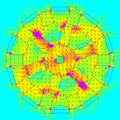
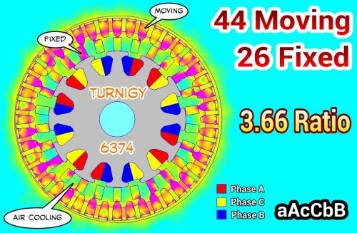
Starting with the Turnigy 6374 Aerodrive motor.
.
.
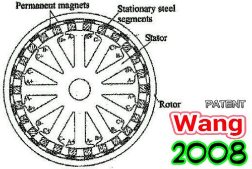
...as it turns out there is a patent from 2008 that took a standard 12 pole stator and added fixed pieces and then put an Outrunner shell on the outside.
.
.
I improved on the design slightly by "going Halbach" with the magnets on the outer shell in order to increase performance, but the stock configuration would be good too. Since there are fixed stator "extensions" there are large air cooling tunnels, so cooling will be very good anyway, but you add extra circulation going down the halbach hybrid route.
Features:
44 Outside Magnetic Poles
26 Fixed Stator "Extensions"
12 Pole Standard Turnigy 6374 Motor Stator
Effective Gear Ratio -> 44 / 12 = 3.667
-------------
So a 6000 rpm motor that was reconfigured this way should behave like it was going at 3.667 times a slower speed or about 1600 rpm.
Take that 1600 rpm and run it through a 5-to-1 magnetic gear reduction and you get a final output of around 300 rpm.
From 300 rpm you can easily do a mechanical gear reduction of 3-to-1 and get to the 100 rpm you need for a mid drive.
--------------
This is very impressive. You basically get a full powered RC motor that through clever use of magnets is "tamed" and made quiet and reliable.
A motor like this in a mid drive would last forever.
.
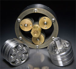
Sprag or Ratchet based Cycloidal Gear?
If you take a Cycloidal Gear basically like this:
.
.
Then you use either a Sprag Clutch:
.
.
Or a regular Ratchet Clutch (Freewheel):
.
.
Now you have something that generates large gear reduction without a lot of fuss.
20-to-1 gear reduction is very possible so 6000 rpm becomes 300 rpm.
Will have to simulate this idea...
.
.
Actually... I'm finding many ideas for Cycloidal Drives online.
The biggest negative seems to be that if the output feeds back into one of these that the system sort of jams up because it does like working in reverse, but for a mid drive which is going to need a freewheel anyway that's not an issue.
.
.
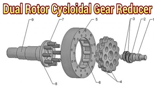
The Dual Rotor Cycloidal Gear Reducer "solves" the vibration issue (for the most part) because the two rotors run opposite each other.
With decent bearings on all the surfaces this looks good:
.
.
...I've even seen triple rotor designs that would reduce vibration even more, but then we are getting into some serious complexity.
This category of "gear reducer" is pretty large and given all the problems ebikes have had with unreliable gear reduction it seems that a very durable concept like this could really help and allow the smaller motors to run free.
Something "more perfect" like magnetic gear reduction seems preferred, but not absolutely required. It would be interesting to see a mid drive developed with a cycloidal gear reducer.
.
Naming Convention Alert !!!
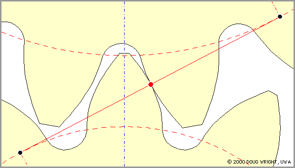
I have seen people on the internet get confused about the usage of the word "Cycloidal".
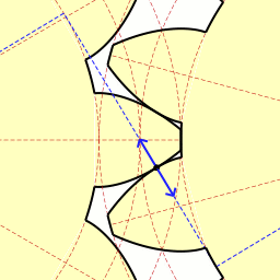
The earliest gears were cut something like this:
.

.
...this was called a "Cycloidal Gear" because the teeth were cut in such a way that the contact was such that rounded edges touched other rounded edges and a lot of friction occurred. This teeth cutting style has become obsolete and was replaced by:
.
.
...which is called an "Involute Gear". The "Involute Gear" shapes it's surfaces so there is almost no slip between gear teeth and that means friction is very low.
Finally we get the last concept:
.

.
...which is called the "Cycloidal Drive" which is basically a separate category that has a variety of implementations.
"Cycloidal Gears" and "Cycloidal Drives" just don't have anything to do with each other.
http://en.m.wikipedia.org/wiki/Cycloidal_drive
The single stage "Cycloidal Drive" can have a 93% efficiency. This compares favorably with a single stage of chain and sprockets, but since on a mid drive we often see multiple gear reduction stages you have to add them up.
Stage 1: 95%
Stage 2: 95%
...overall you get 90% efficiency with a two stage reduction, so the "Cycloidal Drive" can actually have LESS friction.
.
.
The guy calls it a "Wabble Drive" and for the moment I'll go with his terminology.
.
.
What is interesting is that higher gear reduction ratios actually translate into LESS vibration because the relative difference between inner and outer teeth numbers is less.
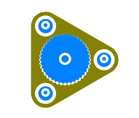
You could also (possibly) move the orbital bearings to the outside.
Drive this one with the bearing to the right and have the left two fixed.
.
.
...this one is "only" 40-to-1. :)
By moving the bearings outside it allows the gears to become smaller. The output is now in the center which allows for a single durable bearing there.
Not sure if driving one will actually get the other two to follow along. In a three dimensional design you could link all three bearings as they normally do with a single driveshaft which would definitely work.
Smaller gears with larger tooth counts (that are wider) will reduce eccentricity and vibration, so there is a strong incentive to push the bearings outside the gears.
.
.
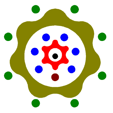
You have to use your imagination on this one...
The eccentric bearing would be "behind" and the outer gear would extend over the top of the inner gear. Then the outer gear has a torque arm which would have a linkage to give it some freedom of movement.
The output gear probably would need it's bearing as if coming out from the animation.
Really need to do this in AutoCAD. (I'm in FEMM)
Same 40-to-1 gear reduction.
Less mass to get oscillating and fewer bearings... just two major bearings and two pivots.
-------------------
Having gone past 250 posts on this topic it's amazing how a fresh new idea comes in... actually there have been several new influences lately.
This could really seriously permit high rpm motors to run at high enough speeds and still be able to get enough gear reduction to drop those speeds to something reasonable.
With a little finesse in the counter balancing it could operate smoothly.
-----------------
Don't forget that you cannot operate this without an additional freewheel. This type of device cannot be run backwards (regen) and would make no sense as part of a hub motor.
I'm still toying with a sprag / ratchet / cycloidal design, but my mind sort of explodes on how to do it. One day maybe. ;)
.
How about putting a solenoid on the arm and oscillating the outer ring which would then rotate the inner ring. This would allow a high frequency short stroke solenoid to rotate a wheel without the use of a cam and gear down several thousand strokes per second to a few hundred rpm. There may be some difficulty getting constant coordinated contact between the central sprocket and the eccentric ring.
With a hammer, a chisle can be made. With a hammer and chistle, files can be made. With hammer, chisle, and file anything else can be made.
Kaishan k500w retired, Merida TEV500 on indefinite sabbatical, currently using a Currie E-zip Trailz.
Yes, definitely.
My mind is filled with so many ideas related to this that I'm having troubles filtering it all down to a single direction to go in.
The idea of using an oscillator instead of a rotating motor is good because with the cycloidal gear we are "already" vibrating... why not just merge the two? (your point)
It seems to get better too. (see next post)
.
.
Just when you think it can't get any better there is the invention above.
http://www.zincland.com/hypocycloid/
Called a "Hypocycloid" or a "Two Stage Cycloidal" this can reduce by a combination of two concurrent cycloidal gears at the same time creating an incomprehensible reduction in a compact package.
.

.
This particular reduction unit has a 100-to-1 ratio.
The trick is that the two gears "handshake" each other and that eliminates the need for a torque arm. Power comes in the input and goes out the output without the need for an external torque arm or the need for spinning needle bearings in an internal shaft. (no positional shafts required)
.
.
The two cycloidal gears are of slighlty different sizes, but close enough to largely balance out each others vibrations. There would be some vibration, but not much... and gear reduction is so high that you are capable of using extremely high rpm motors which maximizes the magnets in them. High speed tends to translate to high power-to-weight ratios.
--------------
For an ebike the following ratio would be ideal:
Cycloidal Gearset 1: 8 --> 7
Cycloidal Gearset 2: 6 --> 7
...which I "think" will create a 7 x 7 = 49-to-1 gear reduction.
Then a 5000 rpm motor will create 100 rpm output ideal for a mid drive.
.
.
These are the two gearsets for the Hypocycloid mentioned previously.
Notice that one spins (the outside ring) faster than the other, but the input is the same.
Since each independent gearset acts in a "handshake" with the other where when one is "active" the other is "floating" they will tend to reposition themselves so as to advance the outer ring more slowly.
The phrase:
"One step forwards, two steps back."
...comes to mind, only in this case it's:
"8/7 step forward, then back up by 6/7 of that." (net result 1/49)
Not sure if all my geometries are correct. (should the gearsets be eccentric relative to each other or should they be aligned in phase or out of phase?)
One gearset acts as the "torque arm" of the other.
Update:
This is a real "no-brainer". The first gearset outer ring is attached to a base (attached to the frame) and the second gearset outer ring runs independently and provides output. It's a simple matter of two gearsets with differing ratios making up a combined output. It's not complicated at all.
Looking at the animations above the output is the "relative difference" in induced rotation speeds of the two gearsets.
Check it out... this is NOT rocket science...
.
A very easy way to get significant gear reduction with high reliability and requiring very little volume. (for an ebike this could be about 1" in diameter)
Commentary
We are all going to look back to the days when mid drives were using multistage gear reduction and probably laugh at how bulky and unreliable they were. This Hypocycloid Reducer seems capable of giving as much gear reduction as we require (which is about 50-to-1) and it does so with minimal effort.
I'm shocked... were we all this dumb? How was this missed?
Who will be the first to try it?
.
.
The exact idea I was thinking about (8-7, 6-7) has been built:
http://www.cnczone.com/forums/linear-and-rotary-motion/72261-backlash-free-rotary-table-13.html#post607728
.
.
Would work great on an ebike as part of a mid drive. (requires additional freewheel)
.
.
This animation is somewhat abstract... but it starts from a zero aligned position and goes through one revolution of the outer gearset and that translates into very little movement on the inner gearset.
The brown dot moves very little.
(it was a lot of work just to produce 9 frames of animation)
It should at least clear your mind on the logic of how it works... it's very simple.
.
.
The Hypocycloid Reducer needs a counterweight.
It should be easy enough to build into the eccentric shaft an extra counterweight that will balance out the oscillations of the gears.
I've heard that it might require some "out of phase" adjustments because the rotation of these gearsets is not in simple circles. (they are hypocycloids)
http://en.m.wikipedia.org/wiki/Hypocycloid
.

.
Even if the vibration cannot be completely removed a counterweight would at least reduce the extremes.
It seems like the main mass of the gearsets should roughly travel in a circle with only the teeth creating some subtle deviations... but I'm not sure.
Seems like a simple crankshaft scenario.
.
.
More video:
.
.
.
.
This will revolutionize the mid drive market !!!
.
This is a nice little animated gif that I pulled out of one of the videos:
.
.
Given the upload limits here that's about as much as can be done.
A screengrab from the video:
.

.
.
Just some more Counter Balancing ideas...
.
.
You can either increase the size of the main bearing and place the Counterweight inside or you can place it on the side.
Another idea would be to have a true "crankshaft" with Counterweights on each side. Since the Two Stage Hypocycloid Reducer has "gears" of different sizes I could imagine two separate weights on either side that compensated exactly for the gear on each side. If done properly you could have almost no vibration even when the motor is spinning at 5000 rpm or above.
.
.
A Side View of the idea of using the larger outside bearing.
Notice how this makes the design more compact over having the Counterweight external to the bearing.
.
.
Okay... so we have the Hypocycloid Reducer above.
What might the math look like in order make it balanced when rotating?
.
.
.
http://en.m.wikipedia.org/wiki/Parallel_axis_theorem
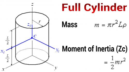
Full Cylinder:
R1 = Average radius of the two eccentric gears.
L1 = Combined width (thickness) of the two eccentric gears.
M1 = Total mass of the two eccentric gears.
I1 = Moment of inertia of the two eccentric gears. (pre-eccentric)
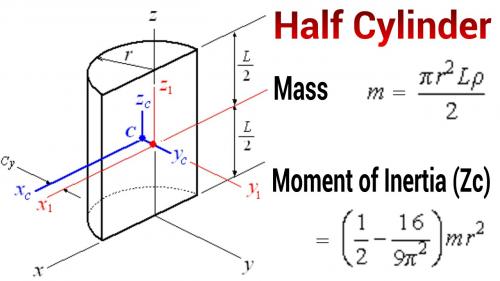
Half Cylinder:
R2 = Radius of the counterweight.
L2 = Width (thickness) of the counterweight.
M2 = Total mass of the counterweight.
I2 = Moment of inertia of the counterweight.
Other Variables:
D = Density of steel. (same for gears and counterweight)
E = Radius of eccentricity of the two eccentric gears.
IE = Moment of inertia of the two eccentric gears. (post-eccentric)
-----------------
For the eccentric gears:
M1 = Pi * (R1)^2 * L1 * D
I1 = (1/2) * M1 * (R1)^2
I1 = (1/2) * (Pi * (R1)^2 * L1 * D) * (R1)^2
I1 = (1/2) * Pi * (R1)^4 * L1 * D
-----------------
For the counterweight:
M2 = (1/2) * Pi * (R2)^2 * L2 * D
I2 = ( (1/2) - (16/(9 * (Pi)^2)) ) * M2 * (R2)^2
I2 = ( (1/2) - (16/(9 * (Pi)^2)) ) * ((1/2) * Pi * (R2)^2 * L2 * D) * (R2)^2
I2 = ( (1/2) - (16/(9 * (Pi)^2)) ) * (1/2) * Pi * (R2)^4 * L2 * D
-----------------
By the Parallel Axis Theorem we get:
Eccentric Moment of Inertia = (Moment of Inertia) + ((Mass) * (Eccentricity)^2)
IE = I1 + ( M1 * (E)^2 )
-----------------
Since the eccentricity of the two gears "creates" the imbalance we want our counterweight to exactly equal the moment of inertia of these two eccentric gears:
.
IE = I2
.
IE = I1 + ( M1 * (E)^2 )
IE = ( (1/2) * Pi * (R1)^4 * L1 * D ) + ( ( Pi * (R1)^2 * L1 * D ) * (E)^2 )
.
I2 = ( (1/2) - (16/(9 * (Pi)^2)) ) * (1/2) * Pi * (R2)^4 * L2 * D
.
Now let's combine the two equations and isolate the eccentricity (E):
.
( (1/2) * Pi * (R1)^4 * L1 * D ) +
( ( Pi * (R1)^2 * L1 * D ) * (E)^2 ) =
.
( ( (1/2) - (16/(9 * (Pi)^2)) ) * (1/2) * Pi * (R2)^4 * L2 * D )
.
Subtracting:
.
( Pi * (R1)^2 * L1 * D * (E)^2 ) =
.
( ( (1/2) - (16/(9 * (Pi)^2)) ) * (1/2) * Pi * (R2)^4 * L2 * D ) -
( (1/2) * Pi * (R1)^4 * L1 * D )
.
Now we see we can remove Pi and D from each part of the equation:
.
( (R1)^2 * L1 * (E)^2 ) =
.
( ( (1/2) - (16/(9 * (Pi)^2)) ) * (1/2) * (R2)^4 * L2 ) -
( (1/2) * (R1)^4 * L1 )
.
Divide by L1:
.
( (R1)^2 * (E)^2 ) =
.
( ( ( (1/2) - (16/(9 * (Pi)^2)) ) * (1/2) * (R2)^4 * L2 ) / L1 ) -
( (1/2) * (R1)^4 )
.
Divide by (R1)^2:
.
(E)^2 =
.
( ( ( (1/2) - (16/(9 * (Pi)^2)) ) * (1/2) * (R2)^4 * L2 ) / ( L1 * (R1)^2 ) ) -
( (1/2) * (R1)^2 )
.
E = sqrt ( ( ( ( (1/2) - (16/(9 * (Pi)^2)) ) * (1/2) * (R2)^4 * L2 ) / ( L1 * (R1)^2 ) ) -
( (1/2) * (R1)^2 ) )
.
Okay, now that's nasty enough that I need to go back and confirm that it's valid (or reasonable) by plugging in some numbers. Will do later.
There are a total of five variables (R1, L1, R2, L2, E) that interact with each other so the equations might need to be redone in order to solve for a desired outome. R2 is the radius of the counterweight, so that might be a good equation to have.
.
.
Plugging these formulas into a spreadsheet is a no-brainer.
I wouldn't bother too much with deriving the pure math equation when you can use a computer to do the math. I just defined the variables in the spreadsheet and then you can manipulate the entire messy equation as a stand alone entity.
Anyway... seems that you need a considerable counterweight to balance a hypocycloid reducer.
The idea of squeezing the counterweight inside a large bearing is not likely going to be enough.
.
.
Gear ratios are not what you think with Hypocycloid Reducers. (at least the two stage ones)
From here:
http://gearotic.com/ESW/FavIcons/index.php?topic=471.15
I/O = (b+1) / (b-a) , where,
I - input speed
O - output speed
a - first (or input) stage ratio
b - second (or output) stage ratio
.
So what's interesting is that in the chart the YELLOW gear ratios are what you think they would be, but outside those combinations it gets very weird.
Just be careful to realize that this is a fractional relationship. Closer ratios of the gearsets will have the highest output ratios, but as they diverge the output ratios go DOWN which is counter intuitive.
It's not as simple as multiplying the ratios together !!!
.
.
I was fiddling with the spreadsheet and looking at the numbers and I believe I made an assumption that was incorrect.
Why would the ENTIRE eccentric gear mass need to be balanced?
Wouldn't you only need to discover the difference between the centered gear mass and the eccentric mass?
If this is the case (and it seems "more intuitive" that it would be) then the counterweight only needs to be big enough to adjust for the eccentricity induced vibration.
.

.
Assuming this is true, then the use of a big bearing makes sense and it would make for a very compact design.
In this example the counterweight is about 1/10 the weight of the gears.
.
.
I did a little more research about eccentricity balancing. The Force of the vibration is defined by the mass times the angular velocity squared times the eccentricity dimension. The balancing mass (Mc) can be at any distance from the center of rotation (r) and that determines how much you need. The longer the counterweight is from the center of rotation the smaller that counterweight can be because e/r where e is the eccentricity of the unbalanced mass.
So it's a ratio... the larger the eccentricity, then the larger the percentage of the eccentric gears that will create an unbalanced condition. But with small eccentricity you will have a small percentage of the eccentric gear mass that needs balancing. You would not equal or exceed 100% until the eccentricity extended beyond the edge of the gears. (which would never happen)
As for the counterweight... there is no fixed weight definition because the distance that the weight is from the center of rotation determines it's apparent mass.
General Guidelines:
Make the eccentricity of the gears as small as possible.
Make the radius of the counterweight as large as possible so that you can reduce it's mass to a level that balances the system.
Apply the formulas using a spreadsheet because it's easier than working out the math in full.
Expect all situations to have a customized solution.
.
.
Many things about the Hypocycloid Reducer defy your common sense.
One interesting thing is looking at the relationship between the size of the gears that will rotate in an eccentric manner and what kind of vibration will result.
It's obvious that as eccentricity increases that vibration will also increase, but since the formula for the increased moment of inertia reduces to:
Vibration = ( Mass of Gear ) * Eccentricity * Eccentricity
Vibration = ( PI() * RadiusGear * RadiusGear ) * Eccentricity * Eccentricity
...we see that both the Radius of the Gear and the Eccentricity increase as squared values.
(numbers in chart are scaled by 1000)
-------------
This suggests that larger gears which operate with smaller eccentricities are better. This is the case with the higher gear reduction ratios.
So the Hypocycloidal Reducer actually vibrates LESS the more gear reduction it performs !!!
.

.
Inrunners are normally unimaginable for ebikes because the high rpm is unworkable.
With a 144-to-1 Hypocycloidal Reducer you could easily:
~720kv * 20v = 14,400 rpm
14,400 rpm / 144 = 100 rpm
...and this is conservative for this motor.
http://www.hobbyking.com/hobbyking/store/__24853__Turnigy_AquaStar_T20_3T_730KV_1280KV_Water_Cooled_Brushless_Motor.html
Max Watts: 5280w
Weight is about two pounds and it's watercooled.
.
.
While there are more moving parts than the Hypocycloidal Reducer there are benefits to "Compound Planetary Gears":
http://en.m.wikipedia.org/wiki/Epicyclic_gearing
.

.
Anyone who ever took an old Sturmey Archer three speed apart would have seen an example of "Compound Planetary Gears".
The negative is that you have the extra planetary gears (which might be fragile) but the positive is that you get the same high gear reductions with better efficiency.
Since you are using conventional gear tooth geometries you can use Involute gears which make sure the teeth aren't sliding against each other creating friction.
.
.
During World War II, a special variation of epicyclic gearing was developed for portable radar gear, where a very high reduction ratio in a small package was needed. This had two outer annular gears, each half the thickness of the other gears. One of these two annular gears was held fixed and had one tooth fewer than did the other. Therefore, several turns of the "sun" gear made the "planet" gears complete a single revolution, which in turn made the rotating annular gear rotate by a single tooth.
------------------
More than anything else the biggest advantage is that "Compound Planetary Gears" have a symmetric geometry which means they are naturally balanced. No need for a counterweight !!!
So "old school" might actually be better or at least easier to make vibration free.
The Rohloff Hub uses this type of gear:
http://www.rohloff.de/en/technology/speedhub/index.html
.
.
Now this takes it a step further...
We begin at NASA:
http://techtransfer.gsfc.nasa.gov/ft_tech_gear_bearings.shtm
Where they talk about a "gear bearing".
.
.
The thinking is that the gear itself takes the place of a bearing so that a planetary gear configuration has fewer breakable parts.
.
.
By placing an electric motor in the middle you now have the dual stage "fractional" gear reduction with very high reduction rates but without as much friction.
--------------
Precise control: Rifle-true anti-backlash produces a planetary transmission with zero backlash, resulting in smoother operation and superior control.
Improved thrust bearing: Gear teeth design give superior thrust bearing performance.
Unprecedented speed reduction: Through phase tuning, a one-tooth difference between ground and output rings is possible, creating opportunities for significant reduction ratios at both low and high speeds (from 0.5:1 to >2,000:1).
Less noise and vibration: More evenly distributed planet loading reduces cyclic loading and rough spots, reducing noise and vibration.
Fewer fatigue failures: Reduced cyclic loading decreases susceptibility to fatigue failures.
Low cost, simple design: Gear bearings combine gear and bearing functions to reduce materials and cost, while also reducing weight and simplifying the design.
High strength: Gear bearings are more structurally rigid and provide higher overall load capacity compared to fixed planetary designs.
.
.
By combining a roller bearing and a spur gear you achieve the ability to perform the gear function with fewer moving parts.
The patent is from 2006 - 2009:
http://www.google.com/patents/US7537541
.
.
In this reducer the center gears spin. Both center gears (124, 134) are actually fixed together even though they are represented as separate in one view. One external ring would be fixed and be considered the input side. The other external ring would be the output side.
The planetary gears would spin freely... causing no output... if the gear ratios were the same on both input and output.
But if the output gears have just one less tooth than the input gears then the output would be a small fraction (one tooth relative to tooth total) compared to the input. The planetary gears spin like crazy, but the output just crawls along !!!
Note that the gear bearings are supported by a ring on the outside edges. This ring acts as the bearing surface and the gear bearing rolls on it like a roller bearing. This is the essential idea of the gear bearing.
.
.
The final step is to insert an electric motor inside one of these reducers. However, one wonders if this last step is necessary and would depend on the configuration you are seeking. For an ebike I can see the "inside motor" design as favorable because it narrows the system overall, but as weight is concerned a more compact external reducer might be better.
There are other very bizarre things about the gear ratios where weird combinations of planetary vs inner vs outer gears create insanely large gear reductions. I need to study that math some more.
.
.
http://techtransfer.gsfc.nasa.gov/newsletter/winter_04.htm#researchprofile
John Vranish
Code 544
18 years at NASA
Education:
B.S., military science,
U.S. Military Academy at West Point;
M.S. electrical engineering,
The George Washington University
Born: Brainerd, Minnesota
...like Klaus Halbach his work may benefit ebikes and deserves mention.
The gear bearing reducer seems perfect for a lightweight gear reduction to transfer power from a high speed small motor to a middrive, a reduction of about 50-to-1.
At present it seems that middrives are using conventional gear reduction strategies that are rather bulky.
-----------
Segmented ground gear transmission (SGGT)
http://www.google.com/patents/US20130337957
His most recent patent (2012) uses planetary gears to create a variable speed transmission which has always been the "Holy Grail" of gear reduction.
From the patent:
This invention is the result of nearly twenty years of periodic efforts by John M. Vranish to find a way to get continuously variable performance from a geared two-stage planetary transmission. The initial work began around 1995 with the first failed attempt and received renewed emphasis in 2005 when John M. Vranish developed two-stage epicyclical planetary gear-bearing transmissions for precision positioning telescopes in NASA applications. The work attracted interest from the NASA commercialization group and efforts turned to finding a way to turn this concept into a continuously variable planetary transmission. The search for a geared CVPT failed repeatedly. Each new approach failed for one of three reasons. 1. The concept violated the “Tooth Count Dilemma”. That is, continuously variable shifting requires the ground ring gear to add teeth to retain proper mesh. 2. Solutions that provided a way around the “Tooth Count Problem,” didn't shift. The Ground gear teeth could move along the planets, but the output would not change. 3. Designs that used moveable grounds shifted speeds at the output, but did not provide mechanical advantage. Also these moveable grounds required extra energy and were wasteful.
---------------
I've attempted to understand the SGGT, but haven't figured it out yet.
.
.
http://m.phys.org/news/2013-11-motor-mars-rover.html
The gear bearing drive, or GBD, as the team's unique actuator is called, consists of a motor embedded directly inside the gear transmission, allowing for cheaper, lighter, and stronger functioning. The GBD is a compact mechanism with two key abilities. It operates as an actuator providing torque and as a joint providing support. Back in 2006, Mavroidis and then graduate student Brian Weinberg developed the idea in collaboration with John Vranish, a NASA Goddard Space Flight Center engineer.
Elias Brassitos, a doctoral candidate in Mavroidis' lab, will use funding from a Space Technology Research Fellowship to develop the GBD for use on the Mars Rover. "For space applications, everything needs to be lighter and stronger," said Brassitos, who noted that the device would replace the entire joint assembly for the rover's manipulator, the arm that extends outside the vehicle to collect rock samples and other things
"Mobile Robotics, particularly the use of rovers as part of a wider NASA exploration strategy, puts pressures on actuation technology," said Brett Kennedy, supervisor of the Robotic Vehicles and Manipulators Group at the Jet Propulsion Laboratory in Pasadena, Calif. "We are always looking for ways to pack more torque, more power, and more functions into smaller packages," added Kennedy, who has high hopes that the GBD will help them do just that.
First, Brassitos must design various GBD architectures, each of which might be good for different applications. He'll design and build a prototype at Northeastern, and then assemble and test the device at the JPL.
While Brassitos works to develop the GBD for space, another graduate student will work to "commercialize it for earth."
.
Pages