Now is a good time to go back over the basics of motor winding.
The chart above describes an imaginary motor with four different winding patterns, but the same total copper fill. The power output of all four windings patterns is the same at 640 watts, but in the first wind (1x8) there is one turn and eight strands creating a low resistance of only 0.1 ohms. As you change the relationship of turns to strands the relative amount of current required changes as does the resistance, but the heat, torque and power all remain constant.
This was discussed recently here on endless-sphere:
...I figured this out in about 2009 or so and it's funny that it's still not crystal clear to everyone over at endless-sphere yet.
------------
There is some ancient history to be aware of...
Long, long ago in the primordial beginnings of EV's there were lead acid batterys (that had voltage sag) and brushed motors with controllers that struggled to supply adequate current. Back in this dark age it took some wizardry to get anything to work.
Those days are gone.
LifePO4 as well as the more flammable Lipo batteries can deliver all the current you will ever need, so the battery is rarely a limitation these days.
Controllers have improved and can supply more power reliably.
Brushed motors have largely been phased out as brushless controllers are now inexpensive and of good quality. Brushed motors imposed a heavy penalty on the use of current because they would overheat the brushes easily if supplied too much. Brushless motors have no such restriction, so current can be whatever you want it to be.
--------
The bottom line is that in the modern era there are no inherent limitations to your choice of windings and since most PWM controllers run efficiently over a reasonably wide range you can simply estimate your desired top speed and match your battery voltage to make the no load rpm match it.
In the modern era our primary concern is weight. We basically are trying to find the most high efficiency method to achieve 250 watts of power output (750 watts USA) while limiting the weight to under 5 lbs. Stealth also seems to be another goal as hostility against ebikes has been rising.
The dream I once had of creating EBRR ("Electric Bicycle Road Racing") that was a sort of spin off of BMX is completely lacking in stealth and seeing the present course where governments are cracking down on excessive power and banning ebikes from publically owned dirt trails things are likely going to become more restrictive than less. A Road Racer ebike is simply asking for trouble.
My guess now is that we will need a purge of the excessively powered ebikes that will flush them out and get those riders to realize they belong on electric motorcycles. Ebikes that are illegal will be confiscated and fines imposed.
.
What if you used a Triple Tree with the center cut out?
That way you could service the battery and motor easily.
You would likely build the frame so that the head tube is a little longer to give it more strength.
Obviously this is only useful for mountain bikes with suspension, but this is an active area for ebikes so not a bad idea overall.
This is also something where you could either ride with the motor and battery or remove it and have very little difference externally. As a rider you would only notice a slight 15 lb difference in weight.
.
Hi, in reply to your reply, not sure how to do this properly as i was only able to read your reply in my email:
"There are over 300 posts on this thread.
If you go back through the thread you will see most every idea that has even
been imagined as it relates to ebike propulsion.
Actually the idea about pedal / generator / motor is very old... and yes, the
problem is that you are just increasing your copper losses (where most losses
come from) by doubling them.
The mid-drive satisfies the combining of pedal power with motor power in a
very elegant way and with the advantage of multispeed gearing through the
derailler it's hard to beat.
A patent from 1898:
.
.
My advice would be to create an image with some paint program that describes
your idea in general ways and upload it here. You can then link your image to
a post and describe it.
As the saying goes:
*"A Picture is Worth a Thousand Words."*
...let's see what you have.
There's a 99% probability it's an old idea that has a dozen patents already.
(so don't worry)
."
Firstly thanks for the reply.
Secondly i am going to put together a prototype just to try to prove the theory to myself but i will let you know right now the concept, i am tired of keeping it to myself since i am not the type of person to take out patents etc. too much paperwork!
So it is so simple that i just don't see why i can't find any info in the concept although mechanically it is not necessarily the best concept for a bike. Although i found your forum whilst looking for clues as to weather my concept may work or not.
I was trying to find a way to make a generate that would produce dc volts without using brushes or electronics. So to cut to the point. When we drop a magnet down a solenoid it deflects the voltage / current in one direction whilst it is falling down the solenoid, so what would happen if the solenoid was infinite? Well it would keep deflecting a dc voltage. Well how can we achieve this? Simple! We make the solenoid into a toroid and the magnets will either fall as the torus moves like a wheel in the vertical plain or we could rotate the magnets around by setting the torus up in a horizontal off centre plain.
Now i am wondering if this is possible so i will test to see if i can make this function or not. After that would come the process of finding practical applications for such a theory.
One idea is to build it into a powerball (the wrist strengthening toy) by building a flywheel out of strong magnets on a hollow bearing and then pass the torus around the gyro. The speeds that we can achieve with the gyro are impressive considering that we are only administering a slow stirring motion with out hand. So what if we could create a mechanical device which would change a slow physical movement into the action required to spin the gyro!?
So most of my ideas here revolve around these theories. But:
There is one last concept i have had that i would like to try to describe to you. It is based around the design of the worlds most powerful electromagnet. This electromagnet is basically made of flat copper discs which are built up with insulating material in-between them however they are joined together so that they form a huge spiral of copper discs. This is not easy to recreate but i have thought of a way to do this on a smaller scale. the idea here is to use this type of flat spiral winding rather than use wire. The advantage is that it will be low voltage and high current when using it as a generator rather than a magnet. Then like before we turn this into a torus by bending one end around to the other. Since the discs will surround the magnet(s) with a much thicker diameter less energy will be wasted as we can collect the energy that is usually wasted in conventional coils, Basically the magnets will be totally encompassed by copper and nothing can escape. (less of the magnetic field will be outside of the device).
Well there you have it, all of my secrets that i will probably never develop but if any of them are worth anything to the world it would be nice to see some sort of credit from the ideas. But it's all come from other things that already exist so… Some of the reasons that they may have not been implemented in the past may be to do with the technology, the materials available or the cost involved in the past. However now with 3d printing incorporated with metal plating onto plastics some of these ideas can be brought to reality.
I hope the concept of torodial dc generator works, obviously there are a million ways to wind such a thing and different ways to add more than one into a device.
Perhaps we need to concentrate more on how we can spin gyros at high speed with a low speed input such as the powerball although i was trying to find low rpm solutions for power generation to begin with.
I hope this is interesting to you, it seems we need to think from a different angle to come up with new ideas or rather find a different way of using existing ideas.
Many people who get into playing around with magnetic flux ideas fall into a very common trap.
That trap is called the "Faraday Paradox".
You cannot think of magnetism as a static thing. Force is only created when there are CHANGING magnetic fields. Think of it like orbiting the earth. If you are in an orbit that is stable you do not accelerate. However if your orbit decreases it's radius then you do accelerate. If you attempt to leave orbit then you decelerate.
Funny because I thought of a similiar idea way back there in this thread. (post 31)
.
.
Lot's of interesting stuff at that company.
Basically that's a torque converter like a NuVinci would function. You can keep your motor at it's optimal rpm and load (making it's peak efficiency and staying cool) and adjusting the effective ratio as needed.
One wonders how efficiently this system operates. If it's 95% efficient then it compares well with gears, chains and belts.
.
I have to build it to see that it won't work for my self, the idea was not to use it as a motor but to try to generate power with it, sorry if it's a bit off subject but there are ways of using similar setups, possibly as a type of motor. A coil gun that is setup as a circle is a bit like a brushless dc motor, hall sensors tell the coils when to fire and the ball accelerates around in circles, with enough coils firing you may be able to get a chain of ball magnets moving at just the right speed to keep the wheel moving, or enough magnets mounted in the rim and a coil that keeps firing them away and pulling them in. But i did see this idea somewhere in the discussion.
I know the idea with the magnet falling down the solenoid shouldn't work but i just can't see what should happen after it completes one revolution of the coil, normally if we drop the magnet down the coil it will deflect the voltage in one direction whilst it falls, just until the point that it exits the coil, so do you expect that once we wrap the coil into a continuous loop that it will deflect the voltage one way until half way around the loop and then it will deflect the voltage the other way until it reaches the beginning again? Or are you thinking it will do one revolution producing a negative voltage and then the next revolution will be positive? Or will it cease to produce electricity after one revolution? If i had to choose one answer i would be going with the half way point theory but i don't see how bending it into a circle would do that. So i'm sticking with the Dc theory which seems impossible from what i have learned in the past. But lets now say that we had a 20mm diameter & 50mm long cylindrical magnet inside a 22mm diameter 200mm long coil and apply dc power across the coil would the magnet shoot out the other side ? (To be honest i'm not sure any more till i build it, i think it will happen with a spherical magnet as it will rotate itself within the solenoid and find itself resting somewhere in the middle of the field), however if we somehow had the magnet held in the correct polarity, perhaps on ceramic bearings then would it shoot out the other side? Or will it ping back in the middle again, i suppose we need to switch the coil off each time the magnet passes it's mid point and then back on again once it's being pushed again. But when i try dropping the magnet through the coil i deflects in one direction until it leaves the coil.
I am confused.
James, I've made the same mistake in this thread too. It's really easy to do it because we tend to see things in absolute (static) terms and not as variable fields.
The Faraday Disk works because the current trails the magnetic field and generates it's own "wave".
These are actually pretty good as energy storage devices but their best feature is handling massive currents. eBikes tend to want high efficiency and use energy sparingly.
----------
Many perpetual motion machine ideas turn out to violate the Faraday Paradox and end up not working. It's probably THE most common mistake and also the hardest to understand. It happens to all of us.
.
We can't always use the laws of magnetics in reverse. Here is an example, if we use a speaker as a microphone we will be able to measure voltage produced from the ac current induced in the voice coil (from the vibrations caused due to air movement) However if we inject a dc source into a speaker the voice coil and cone pops in or out of the resting position (direction depending on polarity (+ to + and the cone pops outwards)) of the magnet and it stays there. now lets say we wanted to reverse this action and produce dc voltage from the speaker, there is no sound i know of that could recreate a dc voltage (this is due to the coil being suspended by the spider, like a spring holding it in the central position) that we could measure at the ends of the voice coil, yes if you push on the cone and hold it there it will cause a current to flow but current flow will quickly vanish. Why is this not a reversible action? If the coil could move an infinite amount within an infinitely long coil then would it keep producing a dv voltage in that polarity as long as the coil was moving through the magnet gap? Obviously this is not a practical example. But what would happen to the current in the coil if we could make the magnet gap into a toroid loop? I'm assuming that once the magnet becomes toroid shaped it's magnetic field would be completely different and the coil would cease to produce power when moving along it's original plain? In this case if i get a magnet to go around and around inside a toroid shaped coil rather than moving through a straight solenoid will it cease to produce a current until i break the ring open so it is no longer a toroid shape? Does this also depend on how the wire or other inductor shaped metal is wound or positioned as there are many different possibilities here. I find it difficult to imagine what would happen to the field when we pass a magnet inside of the toroidal shaped solenoid.
Sorry for this thinking out aloud, I just can't get my head round this, it makes no sense at all to me, laws must change inside the solenoid once we bend it into a toroid?
Force only happens when magnetic fields are changing.
A static uniform magnetic field creates no Force at all.
The typical permanent magnet electric motor creates it's Power by very rapidly alternating the polarity of the magnetic field in coordination with a segmented architecture of alternating permanent magnets.
All electric motors "surf" on magnetic waves in one way or another. (even the Faraday Disk)
Imagine flux as like a valley sided with hills, the steeper the hills, the stronger the Force:
.
Here's a proof:
Transformers operate using Alternating Current.
What happens if you use Direct Current?
Nothing...
The side you apply the Direct Current to will create a magnetic field, but once it's energized (levels off) the secondary coil generates no current.
The Homopolar Motor hasn't changed much in basic design since the Faraday Disk.
These days they are very desireable in situations where immense currents (1000's of Amps) are desired. One might imagine an ebike design which used 3 Volts at 250 Amps to create a 750 Watt motor.
Liquid metal alloys instead of conventional brushes to reduce friction and increase current capability.
High-temperature superconducting magnets that can produce over 10 Teslas.
...it's probably impractical to do this on a small scale, but it's not impossible.
.
.
Upon further reflection about the Faraday Paradox and the Faraday Disk it becomes clear that copper behaves in a unique way when exposed to a magnetic field. In this image above I make it clear that following the path along a uniform field (inward on the "X") does not produce a Force IF YOU ARE CONSIDERING TWO MAGNETIC FIELDS.
.
What makes copper different as a material is that it's actually made up of individual atoms with electrons that are spinning. When you pass a current through copper those electrons "line up" and that creates a magnetic flux "out of nowhere".
So there is sort of an exception to the Faraday Paradox:
"In a uniform magnetic field copper can create a Force if current passes through it."
We see this as being true in cases where the motor is designed to be ironless. In the case of the solar racers they use Halbach Arrays in an Axial Flux design and simply have copper in the middle. The only reason they use Halbach Arrays rather than just two massive magnets on each side (like the Faraday Disk) is that the flux paths are much shorter and that means higher magnetic flux levels. (Teslas)
-------
James (if you are still confused) if your design places copper spinning around inside a toroid somehow that could work. But magnets will not spin in a uniform magnetic field. An alteration to the design might make it work.
.
.
This sort of thing actually does work, but it is like a Faraday Disk and requires massive currents to generate any Force. For an ebike that operates like an arc welder (3 volts, 500 amps) you can generate Power, but you still need to deal with brushes with these scary currents so it's a difficult and impractical solution. Alternating currents with tight magnetic flux loops create a sort of "magnetic waveform" where the magnetic and the electric are better optimized.
--------
In order to increase the voltage you need inductance. Inductance is the property of a copper coil. The more turns of copper you have the more inductance you get and the less current (and more voltage) that is required to generate a magnetic field. This is why higher inductance is desired because lower currents are easier to manage.
.
.
This would work if the copper were to go from the inside to the outside, but you would want a second magnetic set that was reversed in polarity to allow the copper to return from outside to inside or you would end up wasting 50% of the copper. The Force created would go in and out of the page. (an oscillator)
.
Ultimately for every motor design there is a tradeoff of the three dimensions of Force, Magnetism and Current.
The important point to remember is that:
ALL THREE DIMENSIONS REQUIRE RETURN LOOPS
Which is clearly impossible. One of the loops must be "sacrificed" and broken so that the other two loops can complete themselves.
You can break a loop by using alternating magnetic polarity. When the magnetism reverses as the motor rotates this effectively breaks the loop. Alternating current is then also reversing so this also creates a break.
Force can be broken if you create a rail gun like device. (non-rotating)
A Homopolar Motor is an exception because the rotation of the copper disk is actually causing the electrons within the copper to change alignment, so it's as though the Current dimension is reinventing it's coordinates independently. The electrons are likely embedded in the earths magnetic field (or something) so when you alter their spin through movement you get a Force. This likely points to the deeper nature of matter and it's relationship to the universe overall. Anyway, copper is able to create a Force in a uniform magnetic field as long as it's dimensionally capable of doing so. The problems usually crop up when you try to get Current to the copper because that requires some type of brush.
In most design cases the question is always:
"Where do the loops exist and how do they interact with the other dimensions?"
Electric propulsion is always a three dimensional problem. FEMM software is nice to get an idea of what is going on, but it's only in two dimensions. Three dimensional FEMM software would be preferred. (but that's not free)
.
This is an example of how you get creative with electromagnetism.
It's an element of a Transverse Flux motor.
.
.
We know from the Right Hand Rule that Magnetic flux rotates because of Current. This induces the silicon steel horseshoe shaped piece to circulate Magnetic flux. By inserting a slight bend in the shape we get a flux path that jumps from one node to the next. Between those nodes there are magnets and so you create a complete flux loop. We use alternating Current so you create a Force that can drive the motor as it jumps from node to node.
Now you make a realization...
You have now completely separated the "natural" electromagnetism seen in the previous post and replaced it with something entirely new. You are "free" to direct Magnetic flux as you wish. The Force vector and the Current vector are now PARALLEL.
Magnetic flux can bee seen as being much like Current, it's very "bendable" to different shapes.
Switched Reluctance motors completely dispose of the need for magnets and basically just control and focus Magnetic flux.
Parallel Path designs create a switching mechanism that can toggle Magnetic flux between different loops and this is like a transitor circuit.
.
This is an old idea I've been kicking around for some time.
A magnetic clutch should slip when a high torque is applied (like when you apply full throttle on a motor) but as the rpm of the cylinders become more equal the torque equalizes and eventually they become locked as you get to your cruising speed.
Magnets facing magnets "shouldn't" create heat. (not sure, but without iron what heats up?)
And in order to test this I'd need to see if the slipping torque is a constant. Does the clutch slip with the same torque at 100 rpm and at 1000 rpm?
If it's truly constant (the slip torque) then why not attach a 5000 rpm motor directly to the 100 rpm crank / bottom bracket and just let it slip like crazy?
You could even sell "250 Watt Euro Legal" slip clutches. (100 rpm)
If there is no friction with Halbach Cylinders then why even use gears?
...this can be proven with a lab test comparing delivered slip torque verses slip speed. If the slip torque increases, decreases, or remains constant with different speed that might be useful.
The question really becomes:
"Is something being wasted somehow"?
...if there is no lost heat then what isn't creating torque?
-----------
Let me add that I've searched all over the internet for a true magnet-to-magnet slip clutch performance curve and have not yet found that information. Hysteresis magnetic clutches are everywhere and they do have heat problems.
And this also does the same thing as current limiting because if torque is limited by slip it's the same thing as torque being limited by current, so we go back to the "Force Limiting" discussion again.
Electrical RPM = Mechanical RPM * Magnetic Pole Pairs
So basically the more Magnetic Pole Pairs you have means your motors ability to rotate at higher rpm is diminished.
.
.
Added weight comes with additional Magnetic Pole Pairs.
From this we observe something rather obvious:
The Power-To-Weight Ratio is best with Low Pole Count high speed motors.
...however, efficiency is higher in the heavier High Pole Count motors for two reasons. First, it becomes possible to do Direct Drive which removes up to 5% of losses due to friction. Second, it generally takes less Current to drive the High Pole Count motor for the same power output so the Copper is under less Heat stress.
Since light weight is usually very important to a cyclist we can essentially conclude that a Small, Low Pole Count, High Speed motor with adequate gear reduction (50-to-1) will "in most cases" be the optimal solution.
The Mid Drive is generally headed in this direction already.
If we DON'T want a big fat Hub Motor that weighs too much we need to slim things down a bit.
We assume:
The Weight is defined as the number of Magnetic Poles multiplied by some SCALING FACTOR which adjusts the motor width.
The SCALING FACTOR also sets a limit on the Torque.
The Electrical RPM (eRPM) sets a fixed limit to how much we can spin the motor.
Power is defined as the number of Magnetic Poles multiplied by the Radius of the motor, but the Torque is limited with a constant so that we get 1000 Watts of output.
------------
What is the bottom line?
A Hub Motor needs to be ONE EIGHTH the width of an equally productive RC motor.
...but otherwise the two are identical in efficiency. (same Resistance)
------------
If a typical RC motor is 2" wide then the Hub Motor should be only 1/4" wide and with 60 magnets. The BionX D-Series seems to be about right.
The idea of embedding iron "poles" into a carbon fiber bicycle rim has been around since earlier in this thread. The construction of the carbon fiber rim is a topic in and of itself. Go here to review:
Previously I was thinking of having iron and coil sets on both sides because a solid horseshoe electromagnet does not allow the wheel to be removed.
The Quick Release idea would allow the horseshoe electromagnet to be opened up for easy wheel removal which is important if you get a flat tire.
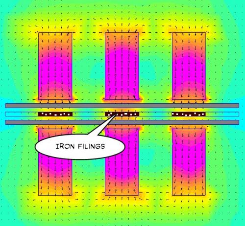
My thoughts are that the Silicon Steel laminations are interwoven in the linkage and that insulation is removed on one side of each lamination so that there is a one-to-one relationship as the flux passes through. This would prevent undesired eddy currents swirling around.
Do we really need Three Phases?
If we design the rim motor to only begin operation when the sensors register movement then we get past the start up problem. There's no reason that Single Phase can't do this job once motion has begun. K.I.S.S.
.
.
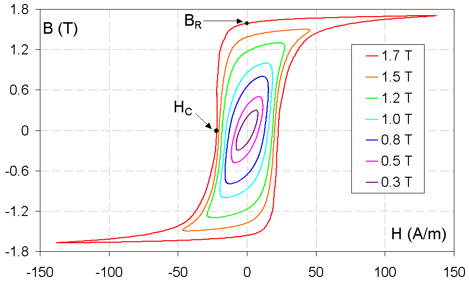
As far as sensors are concerned I see no problem with embedding very small magnets into the rim in between the iron segments OR by simply allowing the iron to retain some of it's Remanence. (allow traces of magnetism to remain, see chart above) It's even possible that this can be done as Single Phase and Single Polarity (unidirectional current) which also reduces complexity in the controller. Switched Reluctance motors don't care about the material they are passing through or if they have some Remanence left over, so a "lazy Single Phase" might actually work, but if it reduces efficiency significantly that would be bad. (once past peak Torque it's desireable to cut the current flow quickly)
It should be possible to use the rear brake bolt as the place where you attach this Switched Reluctance Rim Motor unit.
The brake would be BEHIND the frame (normal) and the motor would be in FRONT of the frame.
Some kind of clamp would attach to the frame so that you can adjust the distance to the rim very precisely. When you Quick Release the motor you are not losing your setting, so when you put the wheel back on it snaps back to it's last position.
In the FEMM simulation I'm able to fully charge this motor with just 8 watts which represents the likely losses the system would endure when operational. I'd have to see what kind of actual power output it generates later. Looking good as an idea though.
This has been discussed endlessly (endless-spherely) but I've never seen an outcome of a discussion that truly captured the real issues properly. I'm going to attempt to do that here... and with great pictures to make it entertaining.
.
.
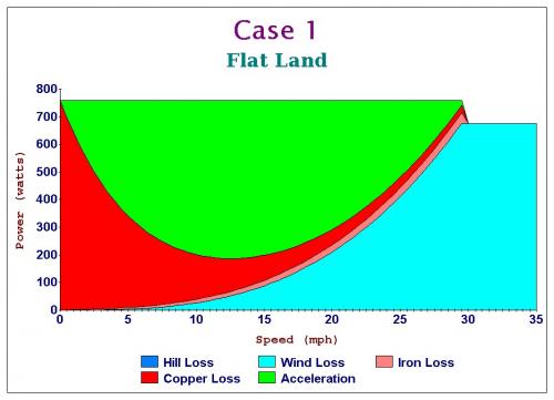
CASE 1 - FLAT LAND
We begin with a quick look at the colors in these charts. They represent derived values of real world conditions using realistic weights and gear ratios. Some will quibble with the details, but overall these are basically the five ways that input power is converted into output. Not all power produces acceleration. Heat can sap large chunks of power and a hill can turn something useful into something awful.
Green is the most useful thing to observe because it represents "what is left" to produce acceleration after accounting for all the other losses.
------------
In the chart above we choose to maximize for SPEED for a 750 watt ebike. We find that if geared for maximum speed we can get to about 30 mph. This is assuming an upright posture typical of a mountain bike.
Simple? Yes... we move on...
.
.
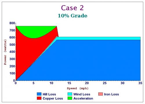
CASE 2 - 10% GRADE
Our happily naive single speed that was set for a maximum speed of 30 mph above fails terribly when one encounters a steep 10% grade. The copper losses go up many times the amount when on a flat surface. The motor is rapidly burning up and things will go very badly for the motor if this continues for very long.
This is a design doomed to fail.
.
.
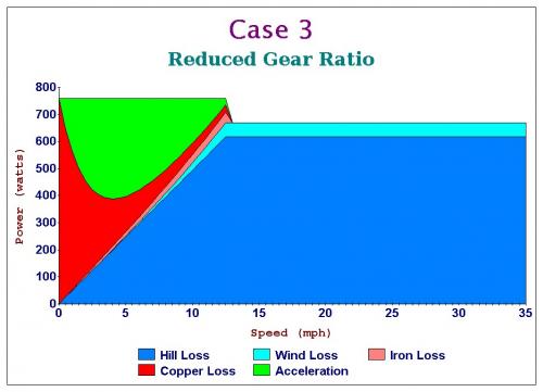
CASE 3 - REDUCED GEAR RATIO
So now all of a sudden we are operating a mid-drive ebike. We downshift to a much lower gear and increase our motor rpm. All of a sudden that 10% grade becomes a non-issue.
Gear reduction (multispeed gearing) allows a fixed motor power to function effectively with a steep hill but one does this AT A SLOWER SPEED than full speed on flat land.
One climbs slowly, but stays cool along the way.
.
.
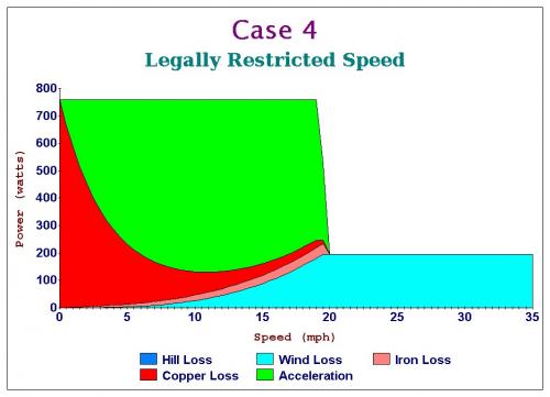
CASE 4 - LEGALLY RESTRICTED SPEED
In America we are typically both limited by a power limit (750 watts) as well as a speed limit (20 mph) so the 30 mph gearing we had in the early examples aren't a great reference point.
At 750 watts of power and 20 mph top speed a single speed has an ABUNDANCE of power.
.
.
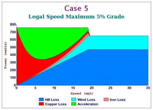
CASE 5 - LEGAL SPEED MAXIMUM 5% GRADE
An ebike designed with 750 watts of power and a top speed of 20 mph will be able to easily climb a 5% grade without overheating. (assuming your ebike isn't 200 lbs or otherwise extreme)
This is an important threshold.
5% grade happens to be the design limitation for most roads in the US. This means that an ebike of normal weight, power and speed can handle the normal grades most of the time. It's a nice law because it's well thought out concerning motor physics.
----------
CONCLUSION
A 750 watt, 20 mph 100% legal single speed ebike is adequate for most places in the US.
EUROPE
Europe has a 250 watt legal limit. This changes everything because the slightest hill will overwhelm these small output motors, so I think it's fair to say that in Europe the multi-speed mid-drive is the only decision one can make. If you want to climb the alps with 250 watts of power a single speed ebike is just plain stupid. With a low enough gear 250 watts can climb ANYTHING VERY SLOWLY.
With a little fiddling in a spreadsheet you can calculate the relationship of a 26" wheels rotation to MPH and if you plot that you get the chart above.
------------
The "bottom line" is that 10 Nm (Newton Meters) is not enough for an ebike.
20 Nm maybe.
30 Nm is more like it.
If you were running a small RC motor with a 10-to-1 gear reduction then:
3 Nm * 10 = 30 Nm
So it's much easier to generate higher Torque with a small motor and gear reduction than with a bigger motor and direct drive. This is why you see "geared hub motors" because designers realized that direct drive is hard to do without making something that weighs too much.
30 Nm (minimum)
-----------
With a 50-to-1 gear reduction we get:
1 Nm * 50 = 50 Nm
...so a little tiny motor that's geared down enough can produce power like something physically much larger. If you are a "weight weenie" who wants a light ebike you probably need to avoid anything that is lacking gear reduction. The John Vranish Gear Bearing Reducer still seems to be an ideal solution. (high reduction in one step)
This is a continuation of the idea of a Switched Reluctance Wheel Motor.
.
.
The way I was approaching this before was to have the magnetic flux pass perpendicular to the wheel. My thinking was that more "circulation" of flux would produce more Force that can be used to create Torque in a wheel.
.
.
But then I tried a different strategy.
What if you created small circles in a sort of figure eight?
The result was a doubling in Force for the same energy.
Why?
As I see it the Force is strongest when there is an "obstruction" in the path of the magnetic flux. So if you have a "low resistance" path coupled with a "high resistance" path the CLOG wants to clear and so the Force will be the highest.
This design could actually get closer to being practical because the Forces are where they should be. If we want 30 Newton Meters of Torque we need a Force on a wheel of about 120 Newtons and since a Switched Reluctance system is only active less than 50% of the time we need about 306 Newtons. (or add more phases)
Each side of the wheel has a Toroid shaped electromagnet coil so efficiency should be very good as no copper is wasted. (no end turns)
A big part of this design strategy is in the materials you would use. Ideally the iron which creates the magnetic flux path and generates the Force is also a functioning part of the wheel strength. The biggest limitation is weight, if it's too heavy then the whole idea falls apart.
.
Okay so now I'm fiddling with the width of these iron regions that transmit magnetic flux and find that there is a peak efficiency.
.
.
Basically the peak occurs at the saturation point of the iron. (1.5 Teslas)
Adding more iron does NOT help.
This is good to know because we want to know the lightest weight solution.
By passing the magnetic flux "sideways" like this it opens up the possibility of using circular shapes because you have in effect created something more like a solenoid in three dimensions. If it were possible to build a wheel with an iron pattern inside and that iron also served to make the wheel strong then it could work. It would be like replacing the spokes with a pattern. Which pattern is most effective will require some thinking.
Honeycomb?
.
.
Such patterns can be structurally sound and also work magnetically.
.
"Which is better? A high Kv motor or a low Kv motor?"
The animation above shows how the motor power changes with different Kv.
One assumption is that you use the same controller with a fixed motor current limit. As the Kv climbs to a higher percentage relative to stock (100%) the powerband "shifts" to higher rpm.
There is always a point where "too much is too much" and that's defined by when you run into wind resistance.
Another factor is hill climbing ability. Unless you upgrade the controller to a higher motor current limit you will lose low end power for hill climbs.
.
.
What is interesting is that with a higher Kv on a hill your "worst case scenario" is actually going to produce LESS heat than with a lower Kv. This is because a higher Kv motor will have lower resistance and so create less heat for the same current. (since Heat = I^2 * R) However, when you are on the hill (5% Grade) and are able to pull successfully to higher rpm the lower Kv is slightly better.
One of the slickest and most stealthy upgrades you can do to a fixed gear ebike is to simply rewind the motor to a higher Kv and that way it can exceed it's 20 mph speed limit while not having to change the battery or controller. If you live in a hilly area it's a bad idea though. Multispeed ebikes like the mid drives don't have to worry about this issue.
SUMMARIZING:
It is the Battery Current Limit that defines the power input of a motor. (Volts x Amps)
The Motor Current Limit often has a maximum based on the controller in use, but Kv is something that is rather flexible. One can choose a higher Kv and attain a powerband that shifts to a higher speed and this does not significantly effect performance.
The easiest stealthy trick is increasing your Kv by rewinding your motor.
.
What if you could triple the peak power of your ebike without burning up the motor?
Well... you actually can, but there are some things to be concerned about.
First you need to determine what is a realistic top speed and get your Kv adjusted so that the motor reaches it's no load speed at that point. Aerodynamics determine this top speed.
You then need to have some idea of what the "continuous heat dissipation" capability is for your motor. In most cases a motor can dissipate about 10% of it's input energy continuously so a 1000 watt input can dissipate about 100 watts all day long.
Notice that in the animation the scale now goes up to 2000 watts.
As we clamp down on the Motor Current relative to the Battery Current we see how the heat (red) drastically reduces. We are left with nearly three times the peak power on top than a stock 750 watt ebike motor.
.
.
Next we need to consider the maximum Grade the ebike will encounter and that will involve some knowledge of your overall weight. You need to do some math and experimenting to figure this out. From this you can subtract the power drain caused by an increasingly steep hill.
There is a point where the hill will "break" this scheme... so be aware that you run the risk of overgearing (increasing the Kv too much) in the search for more top speed. Expect to tinker to get it just right.
.
.
This is actually how my ebike is configured. Peak power is about 3 hp and you can run it all day and not overheat. It's very slow to accelerate below 10 mph, but once you get going it pulls 30 mph like it's nothing. At one point I geared it for 40 mph (which it pulled easily at 50 amps) but changed the gear ratio to make it "more legal" and at this point I'm not interested in dealing with the police about it.
The ebike is in storage and might never be used.
There is also a complete thread dedicated to encouraging this idea for ebike racing.
An ebike with the standard upright rider position and 750 watts of input Power will have an Aerodynamic Drag Coefficient of about 0.50 and be able to go about 30 mph.
The streamlined ebike (recumbent for example) will have a lower drag number (0.25) and gain SEVEN mph for a top speed of about 37 mph.
Most casual bicycle riders produce about 100 watts in an upright position, so typically a regular bicyclist moves along at about 15 mph.
.
Using the same logic as constant Force, the thinking here is that if you have an ebike with a motor that has a fairly well known continuous heat dissipation that you literally design the ebike around that variable.
The Aerodynamic Cooefficient of the ebike sets the limit of how much you can increase the Kv. (as well as electrical rpm for brushless motor controllers)
When you push the limits of aerodynamics you don't really see the negatives until you encounter a hill of 3% Grade or more.
Hills erase all your top end.
What is interesting is that the ebike never exceeds 100 watts of heat, so it never burns up.
.
What we doing here is starting off with something like your ordinary hub motor which can handle about 100 watts of continuous heat, but is typically set up so that it gets pounded by 500 watts in some situations (steep hills or when accelerating from a stop) and then has essentially no heat when on the flat and after accelerating.
We change the behavior of this hub motor (fixed gear) by INCREASING the Battery Current limit while at the same time DECREASING the Phase (also called Motor or Armature) Current.
...this is what I've done on my own ebike and it works exactly as you would expect. The acceleration is perfectly linear from zero up until you hit your limits of wind drag.
There is no "mechanical" change required... just change your controller settings assuming you have a programmable controller like a Kelly.
Your 750 watt hub motor really can produce 2000 peak watts without overheating if you know what you are doing. Just don't be unwise. If you increase the Battery Current you need to reduce your Phase Current because you are "managing heat" by changing it's shape. With the normal setting it's an "averaging" concept where things radically overheat some of the time (low rpm) and then compensate when running at higher rpm. In order to make this compromise you have to seriously underperform in your higher rpm. Hopefully the animation makes this easy to understand.
.
* The negative is that at low rpm power is low. (no burnouts)
* The positive is that power is abundant at full speed and the motor stays very cool.
* This is also very stealthy because you accelerate slowly, but continuously. (more like bicycles)
.
"I live in the Alps and our European laws restrict us to 250 watts of Power. What does that look like when you own a mid-drive?"
Fair enough. Multispeed gearing typically spans no more than 500% relative to the lowest gear, so the animation above shows what that looks like if you have 9 gears.
Note how 8th and 9th produce the same top speed, but 9th just creates more heat.
.
.
Since you are in the Alps you will be climbing hills of at least 5% Grade.
3rd and 4th gear will get you up the 5% Grade at the fastest rate you can go based on 250 watts of Power. (3rd will produce less heat)
5th, 6th, 7th, 8th and 9th gear do nothing but waste more heat and actually begin to reduce performance.
250 watts can be made to climb just about anything if the low gear is low enough. (9% Grade)
Iron Losses actually go down when your gear is too high because the motor is spinning more slowly. By dropping to a lower gear we get a larger drop in Copper Losses (biggest source of heat) but a very slight gain in Iron Losses, so a moderate tradeoff is taking place.
------
Having studied the ebike for nearly a decade now I've come to the conclusion that the "Best" law that should be applied worldwide for ebikes is to simply limit Power Input to something like 250 watts and let people be free to adjust gearing to suit their environment. Once you get above 250 watts you start to get into moped territory.
Throttles also seem to be a bad idea.
If you want to create an ebike that encourages "bicycle like" behavior (but simply enhances it) then it would be better to just have a tachometer on the crank (PAS - Pedal Assist System") and make that the throttle. Some argue for a "torque sensor" which is more complex because it requires knowledge of "effort" which is probably going too far. I have not tested these PAS systems, so there might be reasons that they are done as "torque sensors" and not simple tachometers, so that's an open question to me. It's likely that it's a better rider experience with a "torque sensor".
The European Standard for ebikes looks pretty good, but I'd drop the gear ratio restriction concerning top speed. If someone gears their ebike to go a little faster that should just be allowed because wind resistance will prevent excessive speed. (20 mph on flat land anyway) Same should be true for the US Law, but Power Input should be dropped to 250 watts.
Ideally the law should simply read:
.
-------------------------------------------- "250 watts of Power Input and PAS throttle."
--------------------------------------------
.
.
Knowing how politics works makes me acknowledge that there will likely continue to be many different definitions of an ebike around the world for some time.
.
The idea of direct drive for a mid drive already exists.
So I thought:
"If we are using a PAS system (you always pedal for power) why mount the motor on the right?"
.
.
Then I remembered the "Toroidal Coil" idea and threw in the idea of Switched Reluctance.
The big advantage of the "Toroidal Coil" is the ability to increase copper which is a way to increase electrical efficiency. This also increases torque.
Switched Reluctance will eliminate cogging.
The silicon steel would be segmented with as many poles as makes sense.
Left side mounting allows the full set of chainrings on the right side which expands the range of gear ratios.
Just a concept at this point.
---------
Over on Endless Sphere they are discussing the same idea:
The rapid flashing creates the illusion of rotation.
Here I've added a very low strength magnet into the loop much like they do in the previous youtube video. This gives a bias to the magnetic flux and introduces a small amount of cogging. It only takes about 10 watts to counteract the cogging (overcome backemf) so the extra magnet isn't a big drain on the system and it does make either sensed or sensorless operation easier.
.
.
Single Phase A/C operation where Pedal Power imitates Shaded Pole motors by providing the Startup Torque.
Throw in some exotic graphite nanotube wire in place of the copper and you have yourself a very high tech solution.
Ideally you could sense rotation through backemf and control the motor with no sensors. You would do this by sensing how much the rider is putting into the system. In effect the rider pedals to overcome cogging and the motor responds by delivering the real power during it's power stroke. Sort of like switching from generator to motor 36 times per crank revolution.
Magnet strength should be kept very low... just enough to make sensing possible.


.
Now is a good time to go back over the basics of motor winding.
The chart above describes an imaginary motor with four different winding patterns, but the same total copper fill. The power output of all four windings patterns is the same at 640 watts, but in the first wind (1x8) there is one turn and eight strands creating a low resistance of only 0.1 ohms. As you change the relationship of turns to strands the relative amount of current required changes as does the resistance, but the heat, torque and power all remain constant.
This was discussed recently here on endless-sphere:
http://endless-sphere.com/forums/viewtopic.php?f=2&t=64907
...I figured this out in about 2009 or so and it's funny that it's still not crystal clear to everyone over at endless-sphere yet.
------------
There is some ancient history to be aware of...
Long, long ago in the primordial beginnings of EV's there were lead acid batterys (that had voltage sag) and brushed motors with controllers that struggled to supply adequate current. Back in this dark age it took some wizardry to get anything to work.
Those days are gone.
LifePO4 as well as the more flammable Lipo batteries can deliver all the current you will ever need, so the battery is rarely a limitation these days.
Controllers have improved and can supply more power reliably.
Brushed motors have largely been phased out as brushless controllers are now inexpensive and of good quality. Brushed motors imposed a heavy penalty on the use of current because they would overheat the brushes easily if supplied too much. Brushless motors have no such restriction, so current can be whatever you want it to be.
--------
The bottom line is that in the modern era there are no inherent limitations to your choice of windings and since most PWM controllers run efficiently over a reasonably wide range you can simply estimate your desired top speed and match your battery voltage to make the no load rpm match it.
In the modern era our primary concern is weight. We basically are trying to find the most high efficiency method to achieve 250 watts of power output (750 watts USA) while limiting the weight to under 5 lbs. Stealth also seems to be another goal as hostility against ebikes has been rising.
The dream I once had of creating EBRR ("Electric Bicycle Road Racing") that was a sort of spin off of BMX is completely lacking in stealth and seeing the present course where governments are cracking down on excessive power and banning ebikes from publically owned dirt trails things are likely going to become more restrictive than less. A Road Racer ebike is simply asking for trouble.
My guess now is that we will need a purge of the excessively powered ebikes that will flush them out and get those riders to realize they belong on electric motorcycles. Ebikes that are illegal will be confiscated and fines imposed.
.
.
.
Getting back to this Front Loading idea...
What if you used a Triple Tree with the center cut out?
That way you could service the battery and motor easily.
You would likely build the frame so that the head tube is a little longer to give it more strength.
Obviously this is only useful for mountain bikes with suspension, but this is an active area for ebikes so not a bad idea overall.
This is also something where you could either ride with the motor and battery or remove it and have very little difference externally. As a rider you would only notice a slight 15 lb difference in weight.
.
.
Hi, in reply to your reply, not sure how to do this properly as i was only able to read your reply in my email:
"There are over 300 posts on this thread.
If you go back through the thread you will see most every idea that has even
been imagined as it relates to ebike propulsion.
Actually the idea about pedal / generator / motor is very old... and yes, the
problem is that you are just increasing your copper losses (where most losses
come from) by doubling them.
The mid-drive satisfies the combining of pedal power with motor power in a
very elegant way and with the advantage of multispeed gearing through the
derailler it's hard to beat.
A patent from 1898:
.
.
My advice would be to create an image with some paint program that describes
your idea in general ways and upload it here. You can then link your image to
a post and describe it.
As the saying goes:
*"A Picture is Worth a Thousand Words."*
...let's see what you have.
There's a 99% probability it's an old idea that has a dozen patents already.
(so don't worry)
."
Firstly thanks for the reply.
Secondly i am going to put together a prototype just to try to prove the theory to myself but i will let you know right now the concept, i am tired of keeping it to myself since i am not the type of person to take out patents etc. too much paperwork!
So it is so simple that i just don't see why i can't find any info in the concept although mechanically it is not necessarily the best concept for a bike. Although i found your forum whilst looking for clues as to weather my concept may work or not.
I was trying to find a way to make a generate that would produce dc volts without using brushes or electronics. So to cut to the point. When we drop a magnet down a solenoid it deflects the voltage / current in one direction whilst it is falling down the solenoid, so what would happen if the solenoid was infinite? Well it would keep deflecting a dc voltage. Well how can we achieve this? Simple! We make the solenoid into a toroid and the magnets will either fall as the torus moves like a wheel in the vertical plain or we could rotate the magnets around by setting the torus up in a horizontal off centre plain.
Now i am wondering if this is possible so i will test to see if i can make this function or not. After that would come the process of finding practical applications for such a theory.
One idea is to build it into a powerball (the wrist strengthening toy) by building a flywheel out of strong magnets on a hollow bearing and then pass the torus around the gyro. The speeds that we can achieve with the gyro are impressive considering that we are only administering a slow stirring motion with out hand. So what if we could create a mechanical device which would change a slow physical movement into the action required to spin the gyro!?
So most of my ideas here revolve around these theories. But:
There is one last concept i have had that i would like to try to describe to you. It is based around the design of the worlds most powerful electromagnet. This electromagnet is basically made of flat copper discs which are built up with insulating material in-between them however they are joined together so that they form a huge spiral of copper discs. This is not easy to recreate but i have thought of a way to do this on a smaller scale. the idea here is to use this type of flat spiral winding rather than use wire. The advantage is that it will be low voltage and high current when using it as a generator rather than a magnet. Then like before we turn this into a torus by bending one end around to the other. Since the discs will surround the magnet(s) with a much thicker diameter less energy will be wasted as we can collect the energy that is usually wasted in conventional coils, Basically the magnets will be totally encompassed by copper and nothing can escape. (less of the magnetic field will be outside of the device).
Well there you have it, all of my secrets that i will probably never develop but if any of them are worth anything to the world it would be nice to see some sort of credit from the ideas. But it's all come from other things that already exist so… Some of the reasons that they may have not been implemented in the past may be to do with the technology, the materials available or the cost involved in the past. However now with 3d printing incorporated with metal plating onto plastics some of these ideas can be brought to reality.
I hope the concept of torodial dc generator works, obviously there are a million ways to wind such a thing and different ways to add more than one into a device.
Perhaps we need to concentrate more on how we can spin gyros at high speed with a low speed input such as the powerball although i was trying to find low rpm solutions for power generation to begin with.
I hope this is interesting to you, it seems we need to think from a different angle to come up with new ideas or rather find a different way of using existing ideas.
James
Keep it simple
.
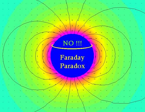
Many people who get into playing around with magnetic flux ideas fall into a very common trap.
That trap is called the "Faraday Paradox".
You cannot think of magnetism as a static thing. Force is only created when there are CHANGING magnetic fields. Think of it like orbiting the earth. If you are in an orbit that is stable you do not accelerate. However if your orbit decreases it's radius then you do accelerate. If you attempt to leave orbit then you decelerate.
Check out:
Toroidal DC Motor Concept - YouTube
www.youtube.com/watch?v=d7AgLZeuIog
My guess is that you are thinking of something like this and it's not likely to work because most motors require alternating fields to function.
.
.
http://www.guinaenergy.com/index.php/history
A very interesting company based in Croatia.
These are big motors:
.
That's 80 Megawatts of power or 80,000,000 watts @ 35k rpm.
This validates my thoughts earlier:
.
.
However, their gear reduction is only about 5-to-1 rather than 50-to-1. (they likely reduce it with secondary planetary gearing)
.
.
Funny because I thought of a similiar idea way back there in this thread. (post 31)
.
.
Lot's of interesting stuff at that company.
Basically that's a torque converter like a NuVinci would function. You can keep your motor at it's optimal rpm and load (making it's peak efficiency and staying cool) and adjusting the effective ratio as needed.
One wonders how efficiently this system operates. If it's 95% efficient then it compares well with gears, chains and belts.
.
I have to build it to see that it won't work for my self, the idea was not to use it as a motor but to try to generate power with it, sorry if it's a bit off subject but there are ways of using similar setups, possibly as a type of motor. A coil gun that is setup as a circle is a bit like a brushless dc motor, hall sensors tell the coils when to fire and the ball accelerates around in circles, with enough coils firing you may be able to get a chain of ball magnets moving at just the right speed to keep the wheel moving, or enough magnets mounted in the rim and a coil that keeps firing them away and pulling them in. But i did see this idea somewhere in the discussion.
I know the idea with the magnet falling down the solenoid shouldn't work but i just can't see what should happen after it completes one revolution of the coil, normally if we drop the magnet down the coil it will deflect the voltage in one direction whilst it falls, just until the point that it exits the coil, so do you expect that once we wrap the coil into a continuous loop that it will deflect the voltage one way until half way around the loop and then it will deflect the voltage the other way until it reaches the beginning again? Or are you thinking it will do one revolution producing a negative voltage and then the next revolution will be positive? Or will it cease to produce electricity after one revolution? If i had to choose one answer i would be going with the half way point theory but i don't see how bending it into a circle would do that. So i'm sticking with the Dc theory which seems impossible from what i have learned in the past. But lets now say that we had a 20mm diameter & 50mm long cylindrical magnet inside a 22mm diameter 200mm long coil and apply dc power across the coil would the magnet shoot out the other side ? (To be honest i'm not sure any more till i build it, i think it will happen with a spherical magnet as it will rotate itself within the solenoid and find itself resting somewhere in the middle of the field), however if we somehow had the magnet held in the correct polarity, perhaps on ceramic bearings then would it shoot out the other side? Or will it ping back in the middle again, i suppose we need to switch the coil off each time the magnet passes it's mid point and then back on again once it's being pushed again. But when i try dropping the magnet through the coil i deflects in one direction until it leaves the coil.
I am confused.
Keep it simple
.
The circle with an "X" means the path is into the image.
.
.
You cannot produce a Force unless you alter your "orbit" so to speak. (a metaphor)
.
.
Faraday Paradox:
http://en.m.wikipedia.org/wiki/Faraday_paradox
James, I've made the same mistake in this thread too. It's really easy to do it because we tend to see things in absolute (static) terms and not as variable fields.
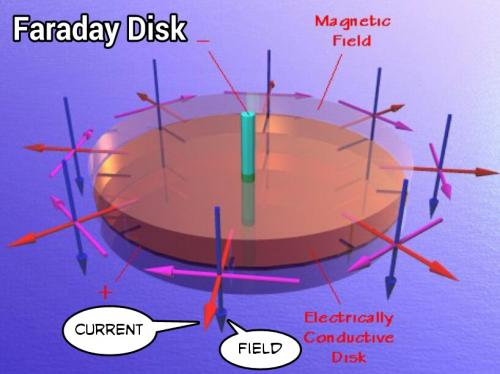
The Faraday Disk works because the current trails the magnetic field and generates it's own "wave".
There are Homopolar Motor / Generators:
http://en.m.wikipedia.org/wiki/Homopolar_generators
These are actually pretty good as energy storage devices but their best feature is handling massive currents. eBikes tend to want high efficiency and use energy sparingly.
----------
Many perpetual motion machine ideas turn out to violate the Faraday Paradox and end up not working. It's probably THE most common mistake and also the hardest to understand. It happens to all of us.
.
We can't always use the laws of magnetics in reverse. Here is an example, if we use a speaker as a microphone we will be able to measure voltage produced from the ac current induced in the voice coil (from the vibrations caused due to air movement) However if we inject a dc source into a speaker the voice coil and cone pops in or out of the resting position (direction depending on polarity (+ to + and the cone pops outwards)) of the magnet and it stays there. now lets say we wanted to reverse this action and produce dc voltage from the speaker, there is no sound i know of that could recreate a dc voltage (this is due to the coil being suspended by the spider, like a spring holding it in the central position) that we could measure at the ends of the voice coil, yes if you push on the cone and hold it there it will cause a current to flow but current flow will quickly vanish. Why is this not a reversible action? If the coil could move an infinite amount within an infinitely long coil then would it keep producing a dv voltage in that polarity as long as the coil was moving through the magnet gap? Obviously this is not a practical example. But what would happen to the current in the coil if we could make the magnet gap into a toroid loop? I'm assuming that once the magnet becomes toroid shaped it's magnetic field would be completely different and the coil would cease to produce power when moving along it's original plain? In this case if i get a magnet to go around and around inside a toroid shaped coil rather than moving through a straight solenoid will it cease to produce a current until i break the ring open so it is no longer a toroid shape? Does this also depend on how the wire or other inductor shaped metal is wound or positioned as there are many different possibilities here. I find it difficult to imagine what would happen to the field when we pass a magnet inside of the toroidal shaped solenoid.
Sorry for this thinking out aloud, I just can't get my head round this, it makes no sense at all to me, laws must change inside the solenoid once we bend it into a toroid?
Keep it simple
The answer is actually very simple.
Force only happens when magnetic fields are changing.
A static uniform magnetic field creates no Force at all.
The typical permanent magnet electric motor creates it's Power by very rapidly alternating the polarity of the magnetic field in coordination with a segmented architecture of alternating permanent magnets.
All electric motors "surf" on magnetic waves in one way or another. (even the Faraday Disk)
Imagine flux as like a valley sided with hills, the steeper the hills, the stronger the Force:
.
Here's a proof:
Transformers operate using Alternating Current.
What happens if you use Direct Current?
Nothing...
The side you apply the Direct Current to will create a magnetic field, but once it's energized (levels off) the secondary coil generates no current.
http://en.m.wikipedia.org/wiki/Transformer
.
.
http://www.guinaenergy.com/index.php/our-technology/homopolar-technology
Homopolar Motor
To make a long story short...
The Homopolar Motor hasn't changed much in basic design since the Faraday Disk.
These days they are very desireable in situations where immense currents (1000's of Amps) are desired. One might imagine an ebike design which used 3 Volts at 250 Amps to create a 750 Watt motor.
http://www.guinaenergy.com/index.php/liquid-metal-brushes
The "tricks" they use are:
Liquid metal alloys instead of conventional brushes to reduce friction and increase current capability.
High-temperature superconducting magnets that can produce over 10 Teslas.
...it's probably impractical to do this on a small scale, but it's not impossible.
.
.
Upon further reflection about the Faraday Paradox and the Faraday Disk it becomes clear that copper behaves in a unique way when exposed to a magnetic field. In this image above I make it clear that following the path along a uniform field (inward on the "X") does not produce a Force IF YOU ARE CONSIDERING TWO MAGNETIC FIELDS.
.
What makes copper different as a material is that it's actually made up of individual atoms with electrons that are spinning. When you pass a current through copper those electrons "line up" and that creates a magnetic flux "out of nowhere".
So there is sort of an exception to the Faraday Paradox:
"In a uniform magnetic field copper can create a Force if current passes through it."
...but field-to-field interactions always require changing fields.
-------
We see this as being true in cases where the motor is designed to be ironless. In the case of the solar racers they use Halbach Arrays in an Axial Flux design and simply have copper in the middle. The only reason they use Halbach Arrays rather than just two massive magnets on each side (like the Faraday Disk) is that the flux paths are much shorter and that means higher magnetic flux levels. (Teslas)
-------
James (if you are still confused) if your design places copper spinning around inside a toroid somehow that could work. But magnets will not spin in a uniform magnetic field. An alteration to the design might make it work.
.
.
This sort of thing actually does work, but it is like a Faraday Disk and requires massive currents to generate any Force. For an ebike that operates like an arc welder (3 volts, 500 amps) you can generate Power, but you still need to deal with brushes with these scary currents so it's a difficult and impractical solution. Alternating currents with tight magnetic flux loops create a sort of "magnetic waveform" where the magnetic and the electric are better optimized.
--------
In order to increase the voltage you need inductance. Inductance is the property of a copper coil. The more turns of copper you have the more inductance you get and the less current (and more voltage) that is required to generate a magnetic field. This is why higher inductance is desired because lower currents are easier to manage.
.
.
This would work if the copper were to go from the inside to the outside, but you would want a second magnetic set that was reversed in polarity to allow the copper to return from outside to inside or you would end up wasting 50% of the copper. The Force created would go in and out of the page. (an oscillator)
.
.
.
Ultimately for every motor design there is a tradeoff of the three dimensions of Force, Magnetism and Current.
The important point to remember is that:
ALL THREE DIMENSIONS REQUIRE RETURN LOOPS
Which is clearly impossible. One of the loops must be "sacrificed" and broken so that the other two loops can complete themselves.
You can break a loop by using alternating magnetic polarity. When the magnetism reverses as the motor rotates this effectively breaks the loop. Alternating current is then also reversing so this also creates a break.
Force can be broken if you create a rail gun like device. (non-rotating)
A Homopolar Motor is an exception because the rotation of the copper disk is actually causing the electrons within the copper to change alignment, so it's as though the Current dimension is reinventing it's coordinates independently. The electrons are likely embedded in the earths magnetic field (or something) so when you alter their spin through movement you get a Force. This likely points to the deeper nature of matter and it's relationship to the universe overall. Anyway, copper is able to create a Force in a uniform magnetic field as long as it's dimensionally capable of doing so. The problems usually crop up when you try to get Current to the copper because that requires some type of brush.
In most design cases the question is always:
"Where do the loops exist and how do they interact with the other dimensions?"
Electric propulsion is always a three dimensional problem. FEMM software is nice to get an idea of what is going on, but it's only in two dimensions. Three dimensional FEMM software would be preferred. (but that's not free)
.
.
This is an example of how you get creative with electromagnetism.
It's an element of a Transverse Flux motor.
.
.
We know from the Right Hand Rule that Magnetic flux rotates because of Current. This induces the silicon steel horseshoe shaped piece to circulate Magnetic flux. By inserting a slight bend in the shape we get a flux path that jumps from one node to the next. Between those nodes there are magnets and so you create a complete flux loop. We use alternating Current so you create a Force that can drive the motor as it jumps from node to node.
Now you make a realization...
You have now completely separated the "natural" electromagnetism seen in the previous post and replaced it with something entirely new. You are "free" to direct Magnetic flux as you wish. The Force vector and the Current vector are now PARALLEL.
Magnetic flux can bee seen as being much like Current, it's very "bendable" to different shapes.
Switched Reluctance motors completely dispose of the need for magnets and basically just control and focus Magnetic flux.
Parallel Path designs create a switching mechanism that can toggle Magnetic flux between different loops and this is like a transitor circuit.
.
.
This is an old idea I've been kicking around for some time.
A magnetic clutch should slip when a high torque is applied (like when you apply full throttle on a motor) but as the rpm of the cylinders become more equal the torque equalizes and eventually they become locked as you get to your cruising speed.
Magnets facing magnets "shouldn't" create heat. (not sure, but without iron what heats up?)
And in order to test this I'd need to see if the slipping torque is a constant. Does the clutch slip with the same torque at 100 rpm and at 1000 rpm?
If it's truly constant (the slip torque) then why not attach a 5000 rpm motor directly to the 100 rpm crank / bottom bracket and just let it slip like crazy?
You could even sell "250 Watt Euro Legal" slip clutches. (100 rpm)
If there is no friction with Halbach Cylinders then why even use gears?
...this can be proven with a lab test comparing delivered slip torque verses slip speed. If the slip torque increases, decreases, or remains constant with different speed that might be useful.
The question really becomes:
"Is something being wasted somehow"?
...if there is no lost heat then what isn't creating torque?
-----------
Let me add that I've searched all over the internet for a true magnet-to-magnet slip clutch performance curve and have not yet found that information. Hysteresis magnetic clutches are everywhere and they do have heat problems.
And this also does the same thing as current limiting because if torque is limited by slip it's the same thing as torque being limited by current, so we go back to the "Force Limiting" discussion again.
Power = Torque * Rpm
----------
http://www.magnadrive.com
.
.
Neodymium magnets and adjustable torque.
.
.
Electrical RPM is a simple concept:
Electrical RPM = Mechanical RPM * Magnetic Pole Pairs
So basically the more Magnetic Pole Pairs you have means your motors ability to rotate at higher rpm is diminished.
.
.
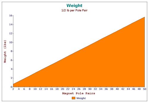
Added weight comes with additional Magnetic Pole Pairs.
From this we observe something rather obvious:
The Power-To-Weight Ratio is best with Low Pole Count high speed motors.
...however, efficiency is higher in the heavier High Pole Count motors for two reasons. First, it becomes possible to do Direct Drive which removes up to 5% of losses due to friction. Second, it generally takes less Current to drive the High Pole Count motor for the same power output so the Copper is under less Heat stress.
Since light weight is usually very important to a cyclist we can essentially conclude that a Small, Low Pole Count, High Speed motor with adequate gear reduction (50-to-1) will "in most cases" be the optimal solution.
The Mid Drive is generally headed in this direction already.
.

.
Higher gear reduction is still desirable.
.

.
.
.
If we DON'T want a big fat Hub Motor that weighs too much we need to slim things down a bit.
We assume:
The Weight is defined as the number of Magnetic Poles multiplied by some SCALING FACTOR which adjusts the motor width.
The SCALING FACTOR also sets a limit on the Torque.
The Electrical RPM (eRPM) sets a fixed limit to how much we can spin the motor.
Power is defined as the number of Magnetic Poles multiplied by the Radius of the motor, but the Torque is limited with a constant so that we get 1000 Watts of output.
------------
What is the bottom line?
A Hub Motor needs to be ONE EIGHTH the width of an equally productive RC motor.
...but otherwise the two are identical in efficiency. (same Resistance)
------------
If a typical RC motor is 2" wide then the Hub Motor should be only 1/4" wide and with 60 magnets. The BionX D-Series seems to be about right.
.
.
Quick Release Switched Reluctance Rim Motor
The idea of embedding iron "poles" into a carbon fiber bicycle rim has been around since earlier in this thread. The construction of the carbon fiber rim is a topic in and of itself. Go here to review:
http://visforvoltage.org/forum/13629-concepts-ebike-propulsion?page=3#comment-71396
.
.
Previously I was thinking of having iron and coil sets on both sides because a solid horseshoe electromagnet does not allow the wheel to be removed.
The Quick Release idea would allow the horseshoe electromagnet to be opened up for easy wheel removal which is important if you get a flat tire.
My thoughts are that the Silicon Steel laminations are interwoven in the linkage and that insulation is removed on one side of each lamination so that there is a one-to-one relationship as the flux passes through. This would prevent undesired eddy currents swirling around.
Do we really need Three Phases?
If we design the rim motor to only begin operation when the sensors register movement then we get past the start up problem. There's no reason that Single Phase can't do this job once motion has begun. K.I.S.S.
.
.
As far as sensors are concerned I see no problem with embedding very small magnets into the rim in between the iron segments OR by simply allowing the iron to retain some of it's Remanence. (allow traces of magnetism to remain, see chart above) It's even possible that this can be done as Single Phase and Single Polarity (unidirectional current) which also reduces complexity in the controller. Switched Reluctance motors don't care about the material they are passing through or if they have some Remanence left over, so a "lazy Single Phase" might actually work, but if it reduces efficiency significantly that would be bad. (once past peak Torque it's desireable to cut the current flow quickly)
http://en.m.wikipedia.org/wiki/Remanence
.
.
It should be possible to use the rear brake bolt as the place where you attach this Switched Reluctance Rim Motor unit.
The brake would be BEHIND the frame (normal) and the motor would be in FRONT of the frame.
Some kind of clamp would attach to the frame so that you can adjust the distance to the rim very precisely. When you Quick Release the motor you are not losing your setting, so when you put the wheel back on it snaps back to it's last position.
In the FEMM simulation I'm able to fully charge this motor with just 8 watts which represents the likely losses the system would endure when operational. I'd have to see what kind of actual power output it generates later. Looking good as an idea though.
.

.
THE SINGLE SPEED VS MULTISPEED DEBATE
This has been discussed endlessly (endless-spherely) but I've never seen an outcome of a discussion that truly captured the real issues properly. I'm going to attempt to do that here... and with great pictures to make it entertaining.
.
.
CASE 1 - FLAT LAND
We begin with a quick look at the colors in these charts. They represent derived values of real world conditions using realistic weights and gear ratios. Some will quibble with the details, but overall these are basically the five ways that input power is converted into output. Not all power produces acceleration. Heat can sap large chunks of power and a hill can turn something useful into something awful.
Green is the most useful thing to observe because it represents "what is left" to produce acceleration after accounting for all the other losses.
------------
In the chart above we choose to maximize for SPEED for a 750 watt ebike. We find that if geared for maximum speed we can get to about 30 mph. This is assuming an upright posture typical of a mountain bike.
Simple? Yes... we move on...
.
.
CASE 2 - 10% GRADE
Our happily naive single speed that was set for a maximum speed of 30 mph above fails terribly when one encounters a steep 10% grade. The copper losses go up many times the amount when on a flat surface. The motor is rapidly burning up and things will go very badly for the motor if this continues for very long.
This is a design doomed to fail.
.
.
CASE 3 - REDUCED GEAR RATIO
So now all of a sudden we are operating a mid-drive ebike. We downshift to a much lower gear and increase our motor rpm. All of a sudden that 10% grade becomes a non-issue.
Gear reduction (multispeed gearing) allows a fixed motor power to function effectively with a steep hill but one does this AT A SLOWER SPEED than full speed on flat land.
One climbs slowly, but stays cool along the way.
.
.
CASE 4 - LEGALLY RESTRICTED SPEED
In America we are typically both limited by a power limit (750 watts) as well as a speed limit (20 mph) so the 30 mph gearing we had in the early examples aren't a great reference point.
At 750 watts of power and 20 mph top speed a single speed has an ABUNDANCE of power.
.
.
CASE 5 - LEGAL SPEED MAXIMUM 5% GRADE
An ebike designed with 750 watts of power and a top speed of 20 mph will be able to easily climb a 5% grade without overheating. (assuming your ebike isn't 200 lbs or otherwise extreme)
This is an important threshold.
5% grade happens to be the design limitation for most roads in the US. This means that an ebike of normal weight, power and speed can handle the normal grades most of the time. It's a nice law because it's well thought out concerning motor physics.
----------
CONCLUSION
A 750 watt, 20 mph 100% legal single speed ebike is adequate for most places in the US.
EUROPE
Europe has a 250 watt legal limit. This changes everything because the slightest hill will overwhelm these small output motors, so I think it's fair to say that in Europe the multi-speed mid-drive is the only decision one can make. If you want to climb the alps with 250 watts of power a single speed ebike is just plain stupid. With a low enough gear 250 watts can climb ANYTHING VERY SLOWLY.
.
.
A simple question:
"How much Torque does a direct drive ebike need?"
------------
Power = Torque * Angular Velocity
Angular Velocity is something that is expressed in Radians per Second. Radians per Second can be converted to RPM by multiplying by 60/2π.
http://en.m.wikipedia.org/wiki/Radian_per_second
With a little fiddling in a spreadsheet you can calculate the relationship of a 26" wheels rotation to MPH and if you plot that you get the chart above.
------------
The "bottom line" is that 10 Nm (Newton Meters) is not enough for an ebike.
20 Nm maybe.
30 Nm is more like it.
If you were running a small RC motor with a 10-to-1 gear reduction then:
3 Nm * 10 = 30 Nm
So it's much easier to generate higher Torque with a small motor and gear reduction than with a bigger motor and direct drive. This is why you see "geared hub motors" because designers realized that direct drive is hard to do without making something that weighs too much.
30 Nm (minimum)
-----------
With a 50-to-1 gear reduction we get:
1 Nm * 50 = 50 Nm
...so a little tiny motor that's geared down enough can produce power like something physically much larger. If you are a "weight weenie" who wants a light ebike you probably need to avoid anything that is lacking gear reduction. The John Vranish Gear Bearing Reducer still seems to be an ideal solution. (high reduction in one step)
.

.
.
This is a continuation of the idea of a Switched Reluctance Wheel Motor.
.
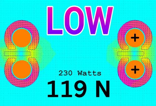
.
The way I was approaching this before was to have the magnetic flux pass perpendicular to the wheel. My thinking was that more "circulation" of flux would produce more Force that can be used to create Torque in a wheel.
.
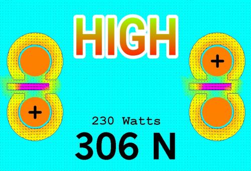
.
But then I tried a different strategy.
What if you created small circles in a sort of figure eight?
The result was a doubling in Force for the same energy.
Why?
As I see it the Force is strongest when there is an "obstruction" in the path of the magnetic flux. So if you have a "low resistance" path coupled with a "high resistance" path the CLOG wants to clear and so the Force will be the highest.
This design could actually get closer to being practical because the Forces are where they should be. If we want 30 Newton Meters of Torque we need a Force on a wheel of about 120 Newtons and since a Switched Reluctance system is only active less than 50% of the time we need about 306 Newtons. (or add more phases)
Each side of the wheel has a Toroid shaped electromagnet coil so efficiency should be very good as no copper is wasted. (no end turns)
A big part of this design strategy is in the materials you would use. Ideally the iron which creates the magnetic flux path and generates the Force is also a functioning part of the wheel strength. The biggest limitation is weight, if it's too heavy then the whole idea falls apart.
.
.
Okay so now I'm fiddling with the width of these iron regions that transmit magnetic flux and find that there is a peak efficiency.
.
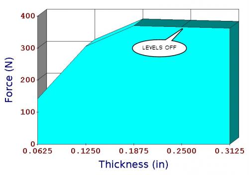
.
Basically the peak occurs at the saturation point of the iron. (1.5 Teslas)
Adding more iron does NOT help.
This is good to know because we want to know the lightest weight solution.
By passing the magnetic flux "sideways" like this it opens up the possibility of using circular shapes because you have in effect created something more like a solenoid in three dimensions. If it were possible to build a wheel with an iron pattern inside and that iron also served to make the wheel strong then it could work. It would be like replacing the spokes with a pattern. Which pattern is most effective will require some thinking.
Honeycomb?
.
.
Such patterns can be structurally sound and also work magnetically.
.
.
A question that pops up a lot goes like:
"Which is better? A high Kv motor or a low Kv motor?"
The animation above shows how the motor power changes with different Kv.
One assumption is that you use the same controller with a fixed motor current limit. As the Kv climbs to a higher percentage relative to stock (100%) the powerband "shifts" to higher rpm.
There is always a point where "too much is too much" and that's defined by when you run into wind resistance.
Another factor is hill climbing ability. Unless you upgrade the controller to a higher motor current limit you will lose low end power for hill climbs.
.
.
What is interesting is that with a higher Kv on a hill your "worst case scenario" is actually going to produce LESS heat than with a lower Kv. This is because a higher Kv motor will have lower resistance and so create less heat for the same current. (since Heat = I^2 * R) However, when you are on the hill (5% Grade) and are able to pull successfully to higher rpm the lower Kv is slightly better.
One of the slickest and most stealthy upgrades you can do to a fixed gear ebike is to simply rewind the motor to a higher Kv and that way it can exceed it's 20 mph speed limit while not having to change the battery or controller. If you live in a hilly area it's a bad idea though. Multispeed ebikes like the mid drives don't have to worry about this issue.
SUMMARIZING:
It is the Battery Current Limit that defines the power input of a motor. (Volts x Amps)
The Motor Current Limit often has a maximum based on the controller in use, but Kv is something that is rather flexible. One can choose a higher Kv and attain a powerband that shifts to a higher speed and this does not significantly effect performance.
The easiest stealthy trick is increasing your Kv by rewinding your motor.
.
.
HIGH PERFORMANCE
What if you could triple the peak power of your ebike without burning up the motor?
Well... you actually can, but there are some things to be concerned about.
First you need to determine what is a realistic top speed and get your Kv adjusted so that the motor reaches it's no load speed at that point. Aerodynamics determine this top speed.
You then need to have some idea of what the "continuous heat dissipation" capability is for your motor. In most cases a motor can dissipate about 10% of it's input energy continuously so a 1000 watt input can dissipate about 100 watts all day long.
Notice that in the animation the scale now goes up to 2000 watts.
As we clamp down on the Motor Current relative to the Battery Current we see how the heat (red) drastically reduces. We are left with nearly three times the peak power on top than a stock 750 watt ebike motor.
.
.
Next we need to consider the maximum Grade the ebike will encounter and that will involve some knowledge of your overall weight. You need to do some math and experimenting to figure this out. From this you can subtract the power drain caused by an increasingly steep hill.
There is a point where the hill will "break" this scheme... so be aware that you run the risk of overgearing (increasing the Kv too much) in the search for more top speed. Expect to tinker to get it just right.
.
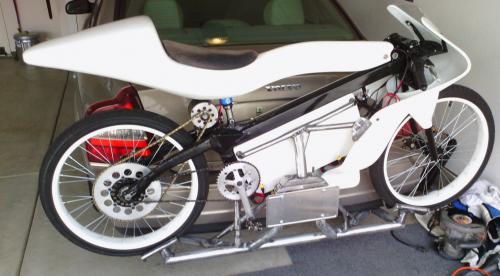
.
This is actually how my ebike is configured. Peak power is about 3 hp and you can run it all day and not overheat. It's very slow to accelerate below 10 mph, but once you get going it pulls 30 mph like it's nothing. At one point I geared it for 40 mph (which it pulled easily at 50 amps) but changed the gear ratio to make it "more legal" and at this point I'm not interested in dealing with the police about it.
The ebike is in storage and might never be used.
There is also a complete thread dedicated to encouraging this idea for ebike racing.
http://visforvoltage.org/forum/13110-force-dyno
.
.
This post is very simple.
An ebike with the standard upright rider position and 750 watts of input Power will have an Aerodynamic Drag Coefficient of about 0.50 and be able to go about 30 mph.
The streamlined ebike (recumbent for example) will have a lower drag number (0.25) and gain SEVEN mph for a top speed of about 37 mph.
Most casual bicycle riders produce about 100 watts in an upright position, so typically a regular bicyclist moves along at about 15 mph.
.
.
The "CONSTANT HEAT MODEL".
Using the same logic as constant Force, the thinking here is that if you have an ebike with a motor that has a fairly well known continuous heat dissipation that you literally design the ebike around that variable.
The Aerodynamic Cooefficient of the ebike sets the limit of how much you can increase the Kv. (as well as electrical rpm for brushless motor controllers)
When you push the limits of aerodynamics you don't really see the negatives until you encounter a hill of 3% Grade or more.
Hills erase all your top end.
What is interesting is that the ebike never exceeds 100 watts of heat, so it never burns up.
.
.
Continuing on this CONSTANT HEAT MODEL concept.
What we doing here is starting off with something like your ordinary hub motor which can handle about 100 watts of continuous heat, but is typically set up so that it gets pounded by 500 watts in some situations (steep hills or when accelerating from a stop) and then has essentially no heat when on the flat and after accelerating.
We change the behavior of this hub motor (fixed gear) by INCREASING the Battery Current limit while at the same time DECREASING the Phase (also called Motor or Armature) Current.
...this is what I've done on my own ebike and it works exactly as you would expect. The acceleration is perfectly linear from zero up until you hit your limits of wind drag.
There is no "mechanical" change required... just change your controller settings assuming you have a programmable controller like a Kelly.
Your 750 watt hub motor really can produce 2000 peak watts without overheating if you know what you are doing. Just don't be unwise. If you increase the Battery Current you need to reduce your Phase Current because you are "managing heat" by changing it's shape. With the normal setting it's an "averaging" concept where things radically overheat some of the time (low rpm) and then compensate when running at higher rpm. In order to make this compromise you have to seriously underperform in your higher rpm. Hopefully the animation makes this easy to understand.
.
* The negative is that at low rpm power is low. (no burnouts)
* The positive is that power is abundant at full speed and the motor stays very cool.
* This is also very stealthy because you accelerate slowly, but continuously. (more like bicycles)
.
.
Okay, so at some point you say something like:
"I live in the Alps and our European laws restrict us to 250 watts of Power. What does that look like when you own a mid-drive?"
Fair enough. Multispeed gearing typically spans no more than 500% relative to the lowest gear, so the animation above shows what that looks like if you have 9 gears.
Note how 8th and 9th produce the same top speed, but 9th just creates more heat.
.
.
Since you are in the Alps you will be climbing hills of at least 5% Grade.
3rd and 4th gear will get you up the 5% Grade at the fastest rate you can go based on 250 watts of Power. (3rd will produce less heat)
5th, 6th, 7th, 8th and 9th gear do nothing but waste more heat and actually begin to reduce performance.
250 watts can be made to climb just about anything if the low gear is low enough. (9% Grade)
Iron Losses actually go down when your gear is too high because the motor is spinning more slowly. By dropping to a lower gear we get a larger drop in Copper Losses (biggest source of heat) but a very slight gain in Iron Losses, so a moderate tradeoff is taking place.
------
Having studied the ebike for nearly a decade now I've come to the conclusion that the "Best" law that should be applied worldwide for ebikes is to simply limit Power Input to something like 250 watts and let people be free to adjust gearing to suit their environment. Once you get above 250 watts you start to get into moped territory.
Throttles also seem to be a bad idea.
If you want to create an ebike that encourages "bicycle like" behavior (but simply enhances it) then it would be better to just have a tachometer on the crank (PAS - Pedal Assist System") and make that the throttle. Some argue for a "torque sensor" which is more complex because it requires knowledge of "effort" which is probably going too far. I have not tested these PAS systems, so there might be reasons that they are done as "torque sensors" and not simple tachometers, so that's an open question to me. It's likely that it's a better rider experience with a "torque sensor".
The European Standard for ebikes looks pretty good, but I'd drop the gear ratio restriction concerning top speed. If someone gears their ebike to go a little faster that should just be allowed because wind resistance will prevent excessive speed. (20 mph on flat land anyway) Same should be true for the US Law, but Power Input should be dropped to 250 watts.
Ideally the law should simply read:
.
--------------------------------------------
"250 watts of Power Input and PAS throttle."
--------------------------------------------
.
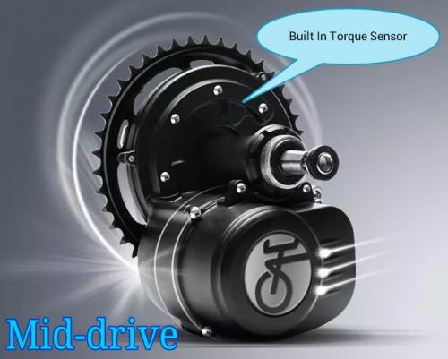
.
Knowing how politics works makes me acknowledge that there will likely continue to be many different definitions of an ebike around the world for some time.
.
.
The idea of direct drive for a mid drive already exists.
So I thought:
"If we are using a PAS system (you always pedal for power) why mount the motor on the right?"
.
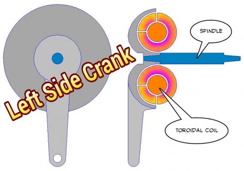
.
Then I remembered the "Toroidal Coil" idea and threw in the idea of Switched Reluctance.
The big advantage of the "Toroidal Coil" is the ability to increase copper which is a way to increase electrical efficiency. This also increases torque.
Switched Reluctance will eliminate cogging.
The silicon steel would be segmented with as many poles as makes sense.
Left side mounting allows the full set of chainrings on the right side which expands the range of gear ratios.
Just a concept at this point.
---------
Over on Endless Sphere they are discussing the same idea:
.
.
http://endless-sphere.com/forums/viewtopic.php?f=30&t=67008&start=50#p1009426
.
.
The rapid flashing creates the illusion of rotation.
Here I've added a very low strength magnet into the loop much like they do in the previous youtube video. This gives a bias to the magnetic flux and introduces a small amount of cogging. It only takes about 10 watts to counteract the cogging (overcome backemf) so the extra magnet isn't a big drain on the system and it does make either sensed or sensorless operation easier.
.
.
Single Phase A/C operation where Pedal Power imitates Shaded Pole motors by providing the Startup Torque.
Throw in some exotic graphite nanotube wire in place of the copper and you have yourself a very high tech solution.
Ideally you could sense rotation through backemf and control the motor with no sensors. You would do this by sensing how much the rider is putting into the system. In effect the rider pedals to overcome cogging and the motor responds by delivering the real power during it's power stroke. Sort of like switching from generator to motor 36 times per crank revolution.
Magnet strength should be kept very low... just enough to make sensing possible.
.
Pages