My name is Michael DiBernardo, I am an honors student at San Jose State University. We are asking for your help. There are not many avenues for us to travel in order to acquire the data need for or project. We feel you are the most knowledgeable individuals and can provide the most accurate responses.
Please Help!!!
This is survey is being done as part of an undergraduate business project for San Jose State University. Your survey responses are completely anonymous and confidential. Data will be used only in the aggregate for academic purposes. The approximate time to complete the survey is about 5 minutes.
Please answer each question as best you can. Thank you in advance for taking the time to participate.
Well, hopefully Michael DiBernardo got some good data.
Time to move on...
.
.
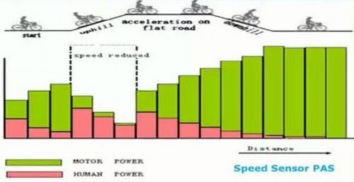
The image above portrays how a simple Speed Sensor would behave as it took over the task the throttle normally performs. Notice how at the times you need power the most (bogged down while pedaling up a hill) the Speed Sensor approach gives the least assistance. When spinning freely on flat land the motor power maximizes and you actually break the speed limit laws for ebike power.
.
.
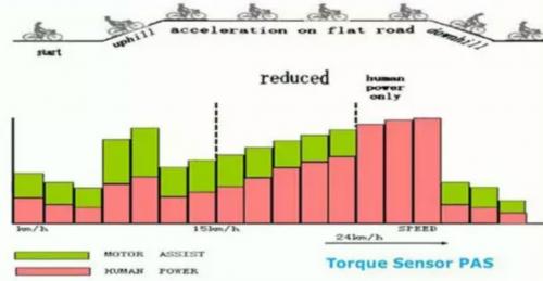
By switching to a true Torque Sensor the power is now where it should be. When you press hard on the pedals the motor responds with equal efforts. When you exceed the speed limit the motor turns off to discourage illegal activity.
This seems to me where it all will end up going.
Like it or not... this is "civilization" in ebike land.
This strategy will actually maximize battery range and minimize human effort which was the original goal of ebikes anyway. (ebikes were never intended to become sport bikes)
.
"The DRV8312-69M-KIT is an InstaSPIN-FOC and InstaSPIN-MOTION technology-based motor control evaluation kit for spinning three-phase brushless DC (BLDC) and brushless AC (BLAC) - or permanent magnet synchronous (PMSM) - motors. Utilizing Texas Instruments’ new InstaSPIN technology, the DRV8312-69M-KIT allows developers to quickly identify, automatically tune, and control a three phase motor, providing an “instantly” stable and functional motor control system. Together with InstaSPIN technology, the DRV8312-69M-KIT provides a high-performance, power-efficient, cost-effective sensorless field-oriented control (FOC) platform that speeds development for quicker time to market. Applications include sub-50-V and 3.5-A synchronous motors for driving pumps, gates, lifts, fans, as well as industrial and consumer robotics and automation."
---------------
This chip has a full software API which seems able to do anything you would want it to do.
A Left Side Mid Drive can be driven without sensors, so the material issues with building such a thing aren't so bad. Software takes time and can be frustrating, but does not require much physical effort.
By moving the motor to the left of the crank it demands that the system is PAS, but I'm seeing that as the inevitable destiny anyway.
This system is gearless and frictionless... but would have slight cogging if the system were turned off. When active the cogging acts as the sensor. In use you would only feel the power assistance.
The chip is Three Phase, but the animation is Single Phase. Either way could work. Single Phase might be easier.
The controller that most ebikes use is called a Buck Converter:
.
.
You can see that the battery provides the maximum voltage (in this case 10 volts) and it then "Steps Down" that voltage to whatever the output is desired to be.
The other type of system is called a Boost Converter:
.
.
The Boost Converter takes the 10 volts and boosts it to 50 volts.
The NHW20 model Toyota Prius HEV uses a 500 V motor. Without a boost converter, the Prius would need nearly 417 cells to power the motor. However, a Prius actually uses only 168 cells and boosts the battery voltage from 202 V to 500 V.
.
The advantage of the Boost Converter is that you can use fewer larger batteries and run a lower pack voltage. I know I'd prefer to have no more than a 4S (~12 volt) pack because then you could use large 60Ah cells much like the cars use. There end up fewer things to worry about and generally the bigger cells are more durable.
The trick to the Boost Converter is an Inductor or Capacitor stores up a pulse of energy with each cycle.
So when you Buck the current increases when the voltage is reduced, but for the Boost the current decreases as you boost the voltage. Otherwise they are very similiar.
.
Linear Technology announces the LT3790, a synchronous buck-boost DC/DC controller that delivers up to 250W of power with a single IC. Its 4.7V to 60V input voltage range makes it ideal for a wide variety of automotive and industrial applications. Its output voltage can be set from 0V to 60V, making it well suited as a voltage regulator or battery/supercapacitor charger.
...
The LT3790 uses four external switching MOSFETs and can deliver up to 250W of continuous output power with efficiencies up to 98.5%. Output current accuracy of ±6% ensures precise current regulation while ±2% output voltage accuracy offers a precise output voltage, making it ideal for charging applications. Multiple LT3790s can be easily paralleled for higher power requirements. Furthermore, its switching frequency can be programmed between 200kHz and 700kHz or synchronized to an external clock.
.
The "ultimate" chip would be a Single Phase back EMF sensing system that could Buck and Boost a 12 Volt pack voltage to a maximum of about 24 Volts on output. This would allow PAS systems on ebikes where there are no sensors and the pack is low voltage and more durable. The motor would be wound so that it's optimal efficiency would occur at about 80-100 rpm which is ordinary pedaling speed.
.
A Speed Sensor based Pedal Assist System (PAS) has a serious problem.
If you simply link pedal rpm to the power the motor creates (linear) then you get this perverse situation where you lack power when you need it and have it when you don't.
In the chart above the Green represents the total percentage of time a skilled cyclist will spent at different pedal rpm over the course of a long ride. Notice how the majority of time things are in a very narrow band.
.
.
What would be better is to have a Non-Linear Speed Sensor PAS which peaked in power at an rpm where one might normally bog down. It has been shown that on difficult climbs the typical cyclist will drop his cadence from 90 rpm down to 70 rpm, so this is the "signal" that a rider is under stress and actually needs the assistance.
You could potentially customize your Non-Linear power curve to fit beginner or expert cyclists.
This is less complex than a Torque Sensor which would require additional hardware.
Combine this idea with the Left Side Crank:
.
.
And now you have a brushless, sensorless, gearless system which can even be run at low voltage. The potential reliability would be impressive. It might be possible to talk about 100,000 miles on such an ebike without repairs. (which by today's standards is difficult)
Just to backtrack a little... the speed would actually be measured by the backEMF of the motor, so there is no actual speed sensor. But there would need to be a computer program that would associate pedal rpm to motor torque and that can be customized to suit the rider.
---------------------------
Update: I've been thinking about this and realized there may be a problem...
How does the system distinguish between the cadence dropping because of a hill and the rider choosing to slow down?
The better Non-Linear shape might be a line from zero to about 60 rpm, then to go flat afterwards. That way if the rider begins to remove his power the rpm will drop in proportion to the reduction and if it gets to 60 rpm and the rider is still not adding effort then the motor power must drop.
The problem of direct drive without a freewheel is once the motor is going it wants to keep going. The Torque Sensor may be a reality you just can't avoid.
.
An alternative approach would be to focus the control algorithm on each cycle of the pedals.
The philosophy would be to fill in the gaps of human pedaling.
You would begin with the Left Crank Motor actually cogging and this resistance will generate power (it's a generator initially) and you can sense this negative voltage. The software then would calculate how much power was being introduced and "match" that amount in those areas where human pedaling typically is lacking.
The system could stop almost immediately because the moment you stop applying positive torque on your main stroke you generate a negative voltage and the motor shuts down. For reasons of safety you need nearly instantaneous "off" like this.
You could also program different shape profiles and possibly even tune them to the individual or you could have a really fancy system that learns how you tend to ride and adapt to you over time. It might even be able to tell when you are getting tired and your circles are getting less round and actually help you when you need it.
.
When you are at your peak pedal torque the motor would behave like it's No-Load condition.
.
When you are between pedal peaks the motor applies it's maximum Torque Boost.
.
The software seeks to always deliver a Constant Torque to the chain which means a perfect circle in the above diagram. The combination of human and motor torque remains constant throughout the cycle.
.
So taking the idea from the previous post the degree that your pedal strokes create a regular (circular) torque will effect how much the motor decides to jump in and help. Since struggling riders tend to get more jerky with their pedaling the motor will jump in to smooth things out.
.
.
When the absolute value of your pedal torque varies then the motor must compensate to match the change in torque levels. By constantly measuring the backEMF in the Left Side Crank Motor you are getting constant feedback about the shape and intensity of the riders stroke. The motor will seem to "magically" know when you are struggling.
.
No need for sensors because you know the position of the Left Side Crank Motor based on the backEMF.
When in motion the alternating patterns of backEMF "per pole" and the cycles of pedal motion give a complex but knowable feedback about what is happening.
One can make choices in the software to favor certain riders and rider styles.
Essentially all the complexity can be removed from the motor itself and since we are dealing with a PAS ("Pedal Assist System") there is no reason to require Three Phases.
Why?
Three Phase power was invented to improve start up performance. We pedal to get things started in a PAS so that issue doesn't exist. Instead we can use a Single Phase design which allows for a toroidal motor construction that massively increases copper fill. With many poles (as many as you want) the Single Phase cycles many times per pedal revolution so there aren't big dead zones in the pedal motion. This is really more like a Step Motor.
It would be a fascinating project to attempt. The software must model human pedal behavior and be able to read the backEMF with high precision and at a rapid rate, but pedal rpm is actually very low compared to most motors (100 rpm) so even with 50 poles the motor seems to be only spinning at 5000 rpm which is nothing for todays electronics to handle.
Tangent represents a shift in strategy. By creating a mechanical advantage of 80:1 between the motor and the crankset, we relieve the stress from the motor and electrics allowing dramatically reduced sizes while increasing power- dramatically. 250ft-lbs of torque are available at the crankset, making the most of wide-ratio bicycle transmissions while low inertia means instant acceleration. The twist throttle setup brings torque on demand so lift the front wheel over that obstacle, power through the rough section, blast that vertical incline, use the berm the way you want. Tangent opens a new world of riding for mountain bikers and allows all the power shenanegans that off-road riders love about riding.
Our reduction ratio means a full 10kRPM rev range is available, creating a powerband useful in any situation. Low end torque for pulling you up and over until you see that straight, then top end scream too fast for a single throw shifter to keep up with.
.
.
...it was really just a matter of time.
Good Job.
The entire unit is a little over 5 pounds. (~2500 watts)
------------------------------
**** Update: ****
Just found this:
.
So this is actually a type of Cycloidal Drive. This will vibrate a great deal which seems to match the video where the motor is very noisy.
The Gear Bearing idea has NOT been done yet after all.
And we found that, with the correct timing, we could. The tooth count comes in digits, but the arrival comes in fractions of a tooth. That's done by phase tuning the tops of the output stages of the planets. We've found a one-tooth difference between ground and output rings is possible, creating opportunities for significant reduction ratios at both low and high speeds (from 0.5:1 to >2,000:1). Gear bearings provide superior speed reduction in a small package. They form rolling friction systems that function both as gears and bearings and are compatible with most gear types, including spur, helical, elliptical, and bevel gears. These self-synchronized components can be in the form of planets, sun, rings, racks, and segments thereof.
.
Harmonic Drives are actually more expensive and more difficult to produce and introduce excessive noise and vibration that runs against the spirit of the ebike.
(1) A “class 1 electric bicycle,” or “low-speed pedal-assisted electric bicycle,” is a bicycle equipped with a motor that provides assistance only when the rider is pedaling, and that ceases to provide assistance when the bicycle reaches the speed of 20 miles per hour.
(2) A “class 2 electric bicycle,” or “low-speed throttle-assisted electric bicycle,” is a bicycle equipped with a motor that may be used exclusively to propel the bicycle, and that is not capable of providing assistance when the bicycle reaches the speed of 20 miles per hour.
(3) A “class 3 electric bicycle,” or “speed pedal-assisted electric bicycle,” is a bicycle equipped with a motor that provides assistance only when the rider is pedaling, and that ceases to provide assistance when the bicycle reaches the speed of 28 miles per hour, and equipped with a speedometer.
----------------
In short the whole concept of the throttle is being phased out in favor of the PAS. (Pedal Assist System)
This really signals the end of any hope of the Electric Bicycle Road Racer as a mainstream product. It could exist at Go Kart tracks as a sort of cult, but there will be no BMX like surge of such a thing.
The laws look to be merging with European Laws that prefer the PAS.
----------------
What this means is that the "Holy Grail" will be something along the lines of the Left Side Crank Motor. This is because with the PAS there is no need for things like freewheels and complicated gear reduction units or even three phase power because pedal motion will always be required to control the motor assistance and power levels will remain low.
.
.
The entire "overpowered ebike" concept will be for private property or just outright illegal.
.
The Wild West days of the ebike have transitioned into the highly regulated commuter vehicle.
.
Once you commit to PAS there is no reason to use Three Phases.
This simplifies things dramatically. You can now design with the expectation of Single Phase and pedal power overcomes the startup problem.
Why people haven't figured this out yet is unclear.
Anyway the Toroidal Chainring Motor is something I'd suggest be attached as a Left Side Crank Motor, but it might be possible to go on the right. By using standard sprocket mounting dimensions a left or right crank mounting of the steel rotor portion becomes easy using standard components. Mounting the stator might be a little tricky... not sure how to do that.
This would be a switched reluctance motor and my guess a Hall Effect gear tooth sensor would be all you need to know pulse timing. Power profiles can be software controlled so that people can program in the type of riding they are after. Casual riding might have a power peak at 80 rpm, while aggressive cycling would place that peak at around 95 rpm... user adjustable of course.
To cut manufacturing costs the stator could be made from one of those silicon steel alloys that are machineable. Once the shape is cut and the cavity created for the copper you would insert the copper inside and glue it in. Installing the stator would involve lining up the matching groves and sliding it into place.
Also, note that I'm making the teeth somewhat smooth. There is a danger with loose tolerances and flex for the rotor to contact the stator and you don't want a major jam to occur. By allowing for this you might scrape a little, but otherwise be okay. The real world needs some wiggle room. If people are riding in the dirt you need it to be scrubbed out naturally.
Toroids permit as much copper as you want so efficiency can be good and torque can be four times greater than radially turned copper coils. (so people claim)
Given that 250 watts will be an often used power output this could do the job.
Are outer rings even necessary for Vranish type fractional gear reduction?
I don't think so.
What if we deviate from the planetary gear configuration?
Think of something simple like a sun gear in the center and another gear that circles around that sun and is connected by the fact they are gears.
.
.
That first set creates a ratio.
Now make a second sun-to-gear set that operates in parallel.
The second set creates a ratio.
Now if you tweek the second set just slightly and get a fractionally different gear ratio your output can be drastically different than your input and at a rate that represents that fractional difference.
The idea would be to hold one sun as fixed and let the second sun float as output.
The two orbiting gears are linked together and are driven by the motor input.
Think of this like a differential... but with one tooth difference.
Fractional Differential Gear Reduction
.
.
The yellow circles are the bearings.
Tooth pitch is the biggest issue. It's likely the fractional gear will require a completely non-standard tooth pitch unless you can get lucky and find a combination that gives the gear reduction you want with standard sizes.
In this animation I've tried to give a cartoon like feel for how fractional gearing works.
The left side sun gear is fixed and has 8 teeth.
The right side sun gear moves and has 7 teeth. (output)
The parallel orbiting gears are represented by the dots and the red one is the actual contact area between the two gears. In this case the orbiting gear pair have the same number of teeth.
What's interesting is that it's possible to have the same sun gear diameter but just change the shape of the teeth. You could also alter the diameter, but you always have to be sure the orbiting gear pair are parallel to the input and output shafts otherwise the teeth shapes get even weirder. (though differentials actually do stuff like that)
In the animation the gear reduction is 7-to-1 or seven turns of input creates one turn of output. Those ratios can go much higher but would have made an animation more work.
So the next logical step is to take the Fractional Differential Gear Reduction concept and insert this into the center of a motor.
The Fractional Differential Gear Reduction would carry the inner magnets of the motor and since this runs on it's own bearings the motor bearings double as the gear reduction bearings producing less overall friction.
Motor speed might max out at 3000 rpm, so a 30-to-1 gear reduction produces an easy to handle 100 rpm, perfect for a mid-drive motor and rather thin too.
This differs from the John Vranish version in that there are no large outer ring gears and since that reduces the technical requirements (precision) it might be easier to make and more capable of accepting imperfect tolerances.
.
Using the standard 12 pole with 14 magnet configuration (very common in RC motors) you can make it an Inrunner so that the inside running rotor is connected to the Fractional Differential Gear Reduction.
36 --> 12 --> 12 -- 35
...one tooth difference makes it a 35-to-1 gear reduction.
The sprocket on the output could go directly to the front chainring in a mid-drive configuration at one-to-one gearing.
The motor is very narrow which makes it ideal for ebikes.
An improved bearing design allowing a simple Axle as drive output:
.
.
Sun Gear Two and the Axle could be made from one piece of steel or it could be press fit or it could use a key and groove or spline... many options.
This whole Fractional gearing concept is very interesting from the strictly mathematical perspective.
By making very slight changes in the number of teeth in the various gears you can arrive at a wide range of final gear ratios.
Starting with Sun gears of around 20 teeth and going through all sorts of subtle differences in the other gears the final ratio can range anywhere from 20-to-1 to 40-to-1.
Trying to seek out all possible options gets tricky because there are essentially four dimensions of tooth counts.
For those that like math puzzles this is a fun one.
.
.
This chart takes all 225 possible combinations of the range of Sun (20-22) and Orbiting gears (10-14) to calculate the final ratio.
Notice how chaotic the pattern becomes.
One needs to have a general idea of the dimensions you have in mind then seek through hundreds of options to find the ideal result. Since tooth pitch is a fairly standard thing it would be best to filter out all the non-conforming sizes.
120-to-1 occurs at:
22 --> 12 --> 11 --> 20
which produces a pair of ratios of:
22/12 = 1.8333 and 20/11 = 1.8182
with a difference of 0.0152 or 99.17% the same:
So on each input revolution the output advances just 0.8% and that means it takes 120 rotations of input to create one rotation of output.
Whenever I stumble into something I always have to remind myself that most everything has already been invented, but people just "forget" because they don't know about it.
A little internet searching and you find that "Differential Reducers" do exist and do provide dramatic gear reduction (100-to-1 or more) with efficiencies in the 99% range.
.
.
Okay, so why hasn't the ebike world discovered this?
Well, one reason might be that you can't reverse these Differential Reduction units and this excludes the possibility of things like regen. But in a mid-drive you don't do regen anyway (you always use a freewheel) so it's a better solution than multiple gear reduction belts and chains.
.
.
The John Vranish Gear Bearing Reducer does appear to pack a higher strength to weight ratio, but it's technically more difficult to build. However, once you start getting into building high precision cut gears it's generally beyond the DIY builder anyway.
Efficiency is really bad using straight cut spur gears like the type you would normally either salvage or buy for a DIY project.
The reason the efficiency is bad is that the orbiting planet gears are moving at a very high speed while the output gear is almost stationary. As a result the orbiting planet gears are always trying to climb up the front edge of the tooth on the slower output gear. This causes lot's of friction. The higher the mismatch (ratio) the worse it gets.
It does look like with different gear shapes you can fix a lot of this efficiency problem, but now you are getting into exotic gears and more money.
The John Vranish Gear Bearing (as I recall) was able to get good efficiency with straight cut gears, so it looks like his design knew about these issues and solved them.
.
What if you used Roller Bearings (needle?) instead of rigid gear teeth?
After creating this image I realized that placing the Roller Bearings in the middle would be a better idea, but that will come later.
Sun 5 --> Orbit 4 --> Orbit 5 --> Sun 6 will create a 24-to-1 reduction.
.
.
This type of product would make it easy for a DIY builder.
Since the contact area is large it might be possible to get away with some type of plastic material that could reduce noise.
The bearings wouldn't have to move all that much, but the small moves will prevent friction from happening. Friction is caused in the Epicyclic Gear Reducers because the teeth start to get ahead of each other and ride up against themselves. The bearings would allow that slight displacement to happen easily.
It also allows really low numbers of "teeth" such as four without any negatives because the bearing can move 15 to 30 degrees if necessary to complete the interaction.
.
.
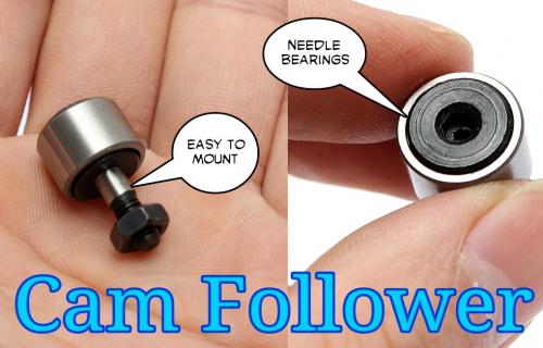
This 35-to-1 Reducer places the Cam Followers in the middle and looks promising. These Cam Followers are designed to withstand high speeds and powerful stresses, so they should hold up here too.
Why not just use two Cam Followers and a Sprocket?
In this case the Sprocket has 67 teeth and the Cam Followers act like 2 teeth, so your overall gear reduction is 33.5-to-1.
This is pretty good and easy to build for the DIY guy.
Also, if you remove one of the Cam Followers you get a "float" period where the rotation of the motor shaft does nothing and this doubles the reduction.
.
.
This Single Cam Follower has a ratio of 40-to-1 but is not smooth in it's power delivery. At 4000 rpm you likely wouldn't notice 40 power pulses per pedal cycle, but it is a factor to consider. This makes a mid-drive easy as the 40-to-1 reduction creates 100 pedal rpm at 4000 motor rpm.
Friction would be extremely low since only 50% of the time there is friction and it would be on Cam Followers with needle bearings, so overall efficiency should be in the 99% range.
By comparison, using a 10 tooth motor gear would require a 400 tooth sprocket gear which is unrealistic. By switching to Cam Followers with needle bearings you effectively reduce your reduction needs by a factor of ten.
With the bigger teeth of the Single Cam Follower it's likely you could build the sprocket out of plastic and reduce noise.
This is a Lavet type motor rotating through one revolution.
Notice how the color changes within the magnet when it's in the two positions where the poles are getting the most access to iron. This slight bias is all that is needed to create the conditions to start up the motor.
.
.
The grooves set at 45 degree angles make sure the magnet settles off the centerline. When the power pulse comes on the magnet "flips" and can't get jammed because it's off the centerline. It then settles into the next and so on.
If one doesn't want any sensoring you can get away without it.
Naturally the first thing you want to do is make the Lavet motor as high performance as possible for the lowest weight. To do this I realized the side positions which limit flux transfer around the magnet are the ideal place to put the copper coils since that's an unused area. You then wrap everything up as tightly as possible to reduce iron requirements. The copper-to-iron ratio is great, lot's of copper, so low resistance and heat.
The motor has 25% of the time when there is no power. These are from 90 degrees (up) to the 135 degree position to the left and on the reverse positions too. So 45 degrees plus 45 degrees means 90 degrees go idle or have reduced torque.
The rest is either a power stroke or if the magnet is strong enough you can let the magnet do all the work. Saturation of the iron is very easy with Neodymium magnets so the whole thing has very high cogging behavior.
In something like a watch the power pulse can exactly be delivered to overcome the cogging force and so very efficient energy usage is possible.
The beginning of the power stroke actually attempts to fight the magnet which means you are applying power to reverse the flux that already exists. This is good in that you are avoiding saturation because you are inhibiting an already nearly saturated iron. What this means is that this type of motor tends to deliver a constant power. So if you want several horsepower in a motor with a smooth delivery this motor is not good at that. However, if you reduce the strength of the magnet you could get better midrange. It all comes down to your magnet-to-iron-saturation ratio... too much magnet and you are forced to full power all the time. (it's like too much cogging)
This would work well for a fairly constant 250 watt mid-drive.
It might be interesting to look into weaker magnets since iron saturation occurs very easily. (or different geometries)
Torque is limited by iron because of saturation. Unless you want to add a lot of excess weight you would need a power pulse that was actually shaped to match the conditions within the Lavet motor. Power applied can be greater in the beginning because you are reversing the flux circulation, but once the flow changes direction and picks up speed it saturates. So a "bang" pulse that tapers is best.
This is a half revolution going from one cogging point to the next.
The last segment (@ 150 degrees) is the "idle zone" where the only torque is from the magnet-to-iron interaction that creates cogging. More "skew" actually increases this "idle zone" size, so it might be wise to see how little "skew" you can get away with.
Torque for 270 watts is around 2-3 Newton Meters which would scale up with the gear reduction (say 30-to-1) to around 60-90 Nm which is where it needs to be.
This idea seems workable and if the power pulse were optimized for the motor geometry efficiency would be good. Very few moving parts, so the only friction and wear would be between to cam and the sprocket.
The magnet is only 3.19 ounces (90.5 g) but the iron and copper would be about 3-4 pounds, so the whole thing would be about 5-6 pounds with sprocket. I'd mount it on the left side and include a freewheel, then use a PAS system for throttle.
Trying a different gif animation maker... hmmmm...
The data looks good.
Weight is less than I thought and the iron is just one pound. Copper would add another pound and the magnet and other mountings would add a third, so the whole thing should be more like three pounds for 250 watts of power.
This is from a very interesting discussion on endless-sphere led by Lebowski about a way to significantly increase field weakening in a DC brushless motor by adding external inductors. Basically the additional inductors allow a kind of electronic advance. Adding external inductors will increase resistance, so there is an efficiency penalty to doing this, but the added rpm could mean being able to achieve a top speed you otherwise would be unable to reach.
.
To mentally comprehend what is happening you need to see motor energy as a kind of spring and voltage as the force you can apply. By adding inductance you increase the holding capacity of that spring and by beginning the voltage earlier (advancing the timing) it allows the same voltage to act longer to build up the motor energy thus delaying the torque maximum. But this is wasteful in the sense the external inductors don't "do" anything other than add resistance. Normally the motor inductance contributes to adding torque to the motor output, but in this case it's wasted.
.
However, if you have something like a hub motor that is limited to 20 mph by design then adding these external inductors could possibly increase top speed to 30 mph with minor losses in performance. It's a stealthy way to get more top speed without having to add more voltage. One wonders if the controller itself could provide this feature since those external inductors could be built into the controller.
.
This exposes the inductance <--> voltage dynamic of the electric motor.
A gyrator can be used to transform a load capacitance into an inductance. At low frequencies and low powers, the behaviour of the gyrator can be reproduced by a small op-amp circuit. This supplies a means of providing an inductive element in a small electronic circuit or integrated circuit. Before the invention of the transistor, coils of wire with large inductance might be used in electronic filters. An inductor can be replaced by a much smaller assembly containing a capacitor, operational amplifiers or transistors, and resistors. This is especially useful in integrated circuit technology.
.
So it could be possible to include this circuit into the controller to simulate an inductor without needing to actually have one.
It also seems possible to make this simulated inductor behave as appearing to have a variable inductance.
Based on how the circuit works I'd think you could achieve high simulated inductance while only getting hit with low resistance. This would mean you could achieve the desired field weakening (timing advance) with far less loss of efficiency. At least that's my "guess".
You might need to replace the op-amp with a MOSFET somehow, or there might be some way to modify the controller circuit itself to incorporate this "side current" of external inductance. Looks like an interesting thing to study.
It seems a little like the "startup capacitor" idea that shifts things out of phase.
.
.
Probably the better way to achieve higher motor rpm is to switch from the Buck (only) converter to something that is both Buck and Boost. There are numerous designs, but the Cuk seems most highly regarded:
Power is always volts times amps, so as the voltage rises (above pack voltage) the amperage would decline in proportion. Doubling voltage is entirely within reason and efficiency can be in the 94% range if done correctly. And in some way these two techniques (field weakening and voltage boosting) are doing the same thing in that they temporarily store energy in a capacitor (or an inductor) before feeding it to the motor. A direct comparison of efficiency might show their outcomes as being similiar.
.
The difference would be that in field weakening you are increasing energy on each individual phase on their own unique cycle. With a buck-boost converter you are raising the pack voltage overall. The question would be if there is some performance advantage to dividing up the phases.

My name is Michael DiBernardo, I am an honors student at San Jose State University. We are asking for your help. There are not many avenues for us to travel in order to acquire the data need for or project. We feel you are the most knowledgeable individuals and can provide the most accurate responses.
Please Help!!!
This is survey is being done as part of an undergraduate business project for San Jose State University. Your survey responses are completely anonymous and confidential. Data will be used only in the aggregate for academic purposes. The approximate time to complete the survey is about 5 minutes.
Please answer each question as best you can. Thank you in advance for taking the time to participate.
https://sjsu.qualtrics.com//SE/?SID=SV_cZnGM9Q9keeLq73
Michael DiBernardo
SJSU Student
Honors Program
Well, hopefully Michael DiBernardo got some good data.
Time to move on...
.
.
The image above portrays how a simple Speed Sensor would behave as it took over the task the throttle normally performs. Notice how at the times you need power the most (bogged down while pedaling up a hill) the Speed Sensor approach gives the least assistance. When spinning freely on flat land the motor power maximizes and you actually break the speed limit laws for ebike power.
.
.
By switching to a true Torque Sensor the power is now where it should be. When you press hard on the pedals the motor responds with equal efforts. When you exceed the speed limit the motor turns off to discourage illegal activity.
This seems to me where it all will end up going.
Like it or not... this is "civilization" in ebike land.
This strategy will actually maximize battery range and minimize human effort which was the original goal of ebikes anyway. (ebikes were never intended to become sport bikes)
.
http://www.ti.com/tool/drv8312-69m-kit
"The DRV8312-69M-KIT is an InstaSPIN-FOC and InstaSPIN-MOTION technology-based motor control evaluation kit for spinning three-phase brushless DC (BLDC) and brushless AC (BLAC) - or permanent magnet synchronous (PMSM) - motors. Utilizing Texas Instruments’ new InstaSPIN technology, the DRV8312-69M-KIT allows developers to quickly identify, automatically tune, and control a three phase motor, providing an “instantly” stable and functional motor control system. Together with InstaSPIN technology, the DRV8312-69M-KIT provides a high-performance, power-efficient, cost-effective sensorless field-oriented control (FOC) platform that speeds development for quicker time to market. Applications include sub-50-V and 3.5-A synchronous motors for driving pumps, gates, lifts, fans, as well as industrial and consumer robotics and automation."
---------------
This chip has a full software API which seems able to do anything you would want it to do.
http://www.ti.com/lit/pdf/spruhj1
A Left Side Mid Drive can be driven without sensors, so the material issues with building such a thing aren't so bad. Software takes time and can be frustrating, but does not require much physical effort.
By moving the motor to the left of the crank it demands that the system is PAS, but I'm seeing that as the inevitable destiny anyway.
This system is gearless and frictionless... but would have slight cogging if the system were turned off. When active the cogging acts as the sensor. In use you would only feel the power assistance.
The chip is Three Phase, but the animation is Single Phase. Either way could work. Single Phase might be easier.
The controller that most ebikes use is called a Buck Converter:
.
.
You can see that the battery provides the maximum voltage (in this case 10 volts) and it then "Steps Down" that voltage to whatever the output is desired to be.
The other type of system is called a Boost Converter:
.
.
The Boost Converter takes the 10 volts and boosts it to 50 volts.
http://en.wikipedia.org/wiki/Boost_converter
.
The NHW20 model Toyota Prius HEV uses a 500 V motor. Without a boost converter, the Prius would need nearly 417 cells to power the motor. However, a Prius actually uses only 168 cells and boosts the battery voltage from 202 V to 500 V.
.
The advantage of the Boost Converter is that you can use fewer larger batteries and run a lower pack voltage. I know I'd prefer to have no more than a 4S (~12 volt) pack because then you could use large 60Ah cells much like the cars use. There end up fewer things to worry about and generally the bigger cells are more durable.
The trick to the Boost Converter is an Inductor or Capacitor stores up a pulse of energy with each cycle.
InputVoltage * InputCurrent = OutputVoltage * OutputCurrent
So when you Buck the current increases when the voltage is reduced, but for the Boost the current decreases as you boost the voltage. Otherwise they are very similiar.
.
This is interesting:
http://eecatalog.com/automotive/2014/12/02/60v-synchronous-buck-boost-controller/
Linear Technology announces the LT3790, a synchronous buck-boost DC/DC controller that delivers up to 250W of power with a single IC. Its 4.7V to 60V input voltage range makes it ideal for a wide variety of automotive and industrial applications. Its output voltage can be set from 0V to 60V, making it well suited as a voltage regulator or battery/supercapacitor charger.
...
The LT3790 uses four external switching MOSFETs and can deliver up to 250W of continuous output power with efficiencies up to 98.5%. Output current accuracy of ±6% ensures precise current regulation while ±2% output voltage accuracy offers a precise output voltage, making it ideal for charging applications. Multiple LT3790s can be easily paralleled for higher power requirements. Furthermore, its switching frequency can be programmed between 200kHz and 700kHz or synchronized to an external clock.
.
.
http://www.linear.com/product/LT3790
The "ultimate" chip would be a Single Phase back EMF sensing system that could Buck and Boost a 12 Volt pack voltage to a maximum of about 24 Volts on output. This would allow PAS systems on ebikes where there are no sensors and the pack is low voltage and more durable. The motor would be wound so that it's optimal efficiency would occur at about 80-100 rpm which is ordinary pedaling speed.
.
.
Input 12 volts @ 20 amps ---> Output 6 volts @ 40 amps
Input 12 volts @ 20 amps ---> Output 12 volts @ 20 amps
Input 12 volts @ 20 amps ---> Output 18 volts @ 13 amps
Input 12 volts @ 20 amps ---> Output 24 volts @ 10 amps
.
A Speed Sensor based Pedal Assist System (PAS) has a serious problem.
If you simply link pedal rpm to the power the motor creates (linear) then you get this perverse situation where you lack power when you need it and have it when you don't.
In the chart above the Green represents the total percentage of time a skilled cyclist will spent at different pedal rpm over the course of a long ride. Notice how the majority of time things are in a very narrow band.
.
http://www.joefrielsblog.com/2012/07/bike-cadence-and-triathlon-race-distance.html
.
What would be better is to have a Non-Linear Speed Sensor PAS which peaked in power at an rpm where one might normally bog down. It has been shown that on difficult climbs the typical cyclist will drop his cadence from 90 rpm down to 70 rpm, so this is the "signal" that a rider is under stress and actually needs the assistance.
You could potentially customize your Non-Linear power curve to fit beginner or expert cyclists.
This is less complex than a Torque Sensor which would require additional hardware.
Combine this idea with the Left Side Crank:
.
.
And now you have a brushless, sensorless, gearless system which can even be run at low voltage. The potential reliability would be impressive. It might be possible to talk about 100,000 miles on such an ebike without repairs. (which by today's standards is difficult)
Just to backtrack a little... the speed would actually be measured by the backEMF of the motor, so there is no actual speed sensor. But there would need to be a computer program that would associate pedal rpm to motor torque and that can be customized to suit the rider.
---------------------------
Update: I've been thinking about this and realized there may be a problem...
How does the system distinguish between the cadence dropping because of a hill and the rider choosing to slow down?
The better Non-Linear shape might be a line from zero to about 60 rpm, then to go flat afterwards. That way if the rider begins to remove his power the rpm will drop in proportion to the reduction and if it gets to 60 rpm and the rider is still not adding effort then the motor power must drop.
The problem of direct drive without a freewheel is once the motor is going it wants to keep going. The Torque Sensor may be a reality you just can't avoid.
.
.
An alternative approach would be to focus the control algorithm on each cycle of the pedals.
The philosophy would be to fill in the gaps of human pedaling.
You would begin with the Left Crank Motor actually cogging and this resistance will generate power (it's a generator initially) and you can sense this negative voltage. The software then would calculate how much power was being introduced and "match" that amount in those areas where human pedaling typically is lacking.
The system could stop almost immediately because the moment you stop applying positive torque on your main stroke you generate a negative voltage and the motor shuts down. For reasons of safety you need nearly instantaneous "off" like this.
You could also program different shape profiles and possibly even tune them to the individual or you could have a really fancy system that learns how you tend to ride and adapt to you over time. It might even be able to tell when you are getting tired and your circles are getting less round and actually help you when you need it.
.
When you are at your peak pedal torque the motor would behave like it's No-Load condition.
.
When you are between pedal peaks the motor applies it's maximum Torque Boost.
.
The software seeks to always deliver a Constant Torque to the chain which means a perfect circle in the above diagram. The combination of human and motor torque remains constant throughout the cycle.
.
.
So taking the idea from the previous post the degree that your pedal strokes create a regular (circular) torque will effect how much the motor decides to jump in and help. Since struggling riders tend to get more jerky with their pedaling the motor will jump in to smooth things out.
.
.
When the absolute value of your pedal torque varies then the motor must compensate to match the change in torque levels. By constantly measuring the backEMF in the Left Side Crank Motor you are getting constant feedback about the shape and intensity of the riders stroke. The motor will seem to "magically" know when you are struggling.
.
.
.
Ultimately everything becomes software.
No need for sensors because you know the position of the Left Side Crank Motor based on the backEMF.
When in motion the alternating patterns of backEMF "per pole" and the cycles of pedal motion give a complex but knowable feedback about what is happening.
One can make choices in the software to favor certain riders and rider styles.
Essentially all the complexity can be removed from the motor itself and since we are dealing with a PAS ("Pedal Assist System") there is no reason to require Three Phases.
Why?
Three Phase power was invented to improve start up performance. We pedal to get things started in a PAS so that issue doesn't exist. Instead we can use a Single Phase design which allows for a toroidal motor construction that massively increases copper fill. With many poles (as many as you want) the Single Phase cycles many times per pedal revolution so there aren't big dead zones in the pedal motion. This is really more like a Step Motor.
It would be a fascinating project to attempt. The software must model human pedal behavior and be able to read the backEMF with high precision and at a rapid rate, but pedal rpm is actually very low compared to most motors (100 rpm) so even with 50 poles the motor seems to be only spinning at 5000 rpm which is nothing for todays electronics to handle.
This whole idea is doable.
.
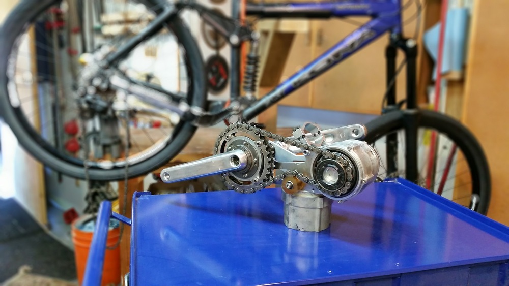
It looks like the Gear Bearing might have been actually realized.
http://www.tangentmotors.com/ascent
Tangent represents a shift in strategy. By creating a mechanical advantage of 80:1 between the motor and the crankset, we relieve the stress from the motor and electrics allowing dramatically reduced sizes while increasing power- dramatically. 250ft-lbs of torque are available at the crankset, making the most of wide-ratio bicycle transmissions while low inertia means instant acceleration. The twist throttle setup brings torque on demand so lift the front wheel over that obstacle, power through the rough section, blast that vertical incline, use the berm the way you want. Tangent opens a new world of riding for mountain bikers and allows all the power shenanegans that off-road riders love about riding.
Our reduction ratio means a full 10kRPM rev range is available, creating a powerband useful in any situation. Low end torque for pulling you up and over until you see that straight, then top end scream too fast for a single throw shifter to keep up with.
.
.
...it was really just a matter of time.
Good Job.
The entire unit is a little over 5 pounds. (~2500 watts)
------------------------------
**** Update: ****
Just found this:
.
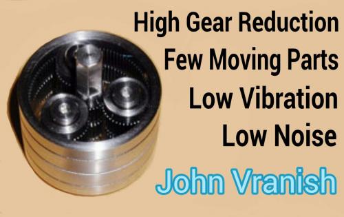
So this is actually a type of Cycloidal Drive. This will vibrate a great deal which seems to match the video where the motor is very noisy.
The Gear Bearing idea has NOT been done yet after all.
(still pretty cool)
.

.
.
.
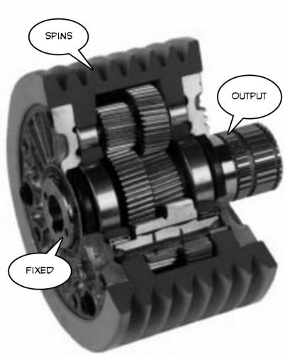
Just wanted to restate the importance of the Gear Bearing Reduction Drive as invented by John Vranish at NASA:
.
http://www.gearsolutions.com/article/detail/6321/the-future-of-gear-bearing-technology
And we found that, with the correct timing, we could. The tooth count comes in digits, but the arrival comes in fractions of a tooth. That's done by phase tuning the tops of the output stages of the planets. We've found a one-tooth difference between ground and output rings is possible, creating opportunities for significant reduction ratios at both low and high speeds (from 0.5:1 to >2,000:1). Gear bearings provide superior speed reduction in a small package. They form rolling friction systems that function both as gears and bearings and are compatible with most gear types, including spur, helical, elliptical, and bevel gears. These self-synchronized components can be in the form of planets, sun, rings, racks, and segments thereof.
.
Harmonic Drives are actually more expensive and more difficult to produce and introduce excessive noise and vibration that runs against the spirit of the ebike.
.
.
Proposed New Ebike Laws for California:
.
(1) A “class 1 electric bicycle,” or “low-speed pedal-assisted electric bicycle,” is a bicycle equipped with a motor that provides assistance only when the rider is pedaling, and that ceases to provide assistance when the bicycle reaches the speed of 20 miles per hour.
(2) A “class 2 electric bicycle,” or “low-speed throttle-assisted electric bicycle,” is a bicycle equipped with a motor that may be used exclusively to propel the bicycle, and that is not capable of providing assistance when the bicycle reaches the speed of 20 miles per hour.
(3) A “class 3 electric bicycle,” or “speed pedal-assisted electric bicycle,” is a bicycle equipped with a motor that provides assistance only when the rider is pedaling, and that ceases to provide assistance when the bicycle reaches the speed of 28 miles per hour, and equipped with a speedometer.
----------------
In short the whole concept of the throttle is being phased out in favor of the PAS. (Pedal Assist System)
This really signals the end of any hope of the Electric Bicycle Road Racer as a mainstream product. It could exist at Go Kart tracks as a sort of cult, but there will be no BMX like surge of such a thing.
The laws look to be merging with European Laws that prefer the PAS.
----------------
What this means is that the "Holy Grail" will be something along the lines of the Left Side Crank Motor. This is because with the PAS there is no need for things like freewheels and complicated gear reduction units or even three phase power because pedal motion will always be required to control the motor assistance and power levels will remain low.
.
.
The entire "overpowered ebike" concept will be for private property or just outright illegal.
.
The Wild West days of the ebike have transitioned into the highly regulated commuter vehicle.
.
.
The properly built Vranish Gearbearing Reducer is technically very difficult to build.
I was thinking it would be possible to get a fairly compact gear reduction in a DIY ("Do It Yourself") way building it up as separate stages.
Later I'll improve on the sketch. (has errors... more to remind me of the idea)
.
.
.
.
Once you commit to PAS there is no reason to use Three Phases.
This simplifies things dramatically. You can now design with the expectation of Single Phase and pedal power overcomes the startup problem.
Why people haven't figured this out yet is unclear.
Anyway the Toroidal Chainring Motor is something I'd suggest be attached as a Left Side Crank Motor, but it might be possible to go on the right. By using standard sprocket mounting dimensions a left or right crank mounting of the steel rotor portion becomes easy using standard components. Mounting the stator might be a little tricky... not sure how to do that.
This would be a switched reluctance motor and my guess a Hall Effect gear tooth sensor would be all you need to know pulse timing. Power profiles can be software controlled so that people can program in the type of riding they are after. Casual riding might have a power peak at 80 rpm, while aggressive cycling would place that peak at around 95 rpm... user adjustable of course.
To cut manufacturing costs the stator could be made from one of those silicon steel alloys that are machineable. Once the shape is cut and the cavity created for the copper you would insert the copper inside and glue it in. Installing the stator would involve lining up the matching groves and sliding it into place.
Also, note that I'm making the teeth somewhat smooth. There is a danger with loose tolerances and flex for the rotor to contact the stator and you don't want a major jam to occur. By allowing for this you might scrape a little, but otherwise be okay. The real world needs some wiggle room. If people are riding in the dirt you need it to be scrubbed out naturally.
Toroids permit as much copper as you want so efficiency can be good and torque can be four times greater than radially turned copper coils. (so people claim)
Given that 250 watts will be an often used power output this could do the job.
.
.
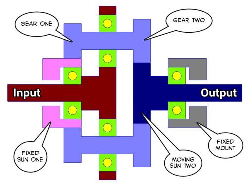
Are outer rings even necessary for Vranish type fractional gear reduction?
I don't think so.
What if we deviate from the planetary gear configuration?
Think of something simple like a sun gear in the center and another gear that circles around that sun and is connected by the fact they are gears.
.

.
That first set creates a ratio.
Now make a second sun-to-gear set that operates in parallel.
The second set creates a ratio.
Now if you tweek the second set just slightly and get a fractionally different gear ratio your output can be drastically different than your input and at a rate that represents that fractional difference.
The idea would be to hold one sun as fixed and let the second sun float as output.
The two orbiting gears are linked together and are driven by the motor input.
Think of this like a differential... but with one tooth difference.
Fractional Differential Gear Reduction
.
.
The yellow circles are the bearings.
Tooth pitch is the biggest issue. It's likely the fractional gear will require a completely non-standard tooth pitch unless you can get lucky and find a combination that gives the gear reduction you want with standard sizes.
There are no outside ring gears.
.
.
In this animation I've tried to give a cartoon like feel for how fractional gearing works.
The left side sun gear is fixed and has 8 teeth.
The right side sun gear moves and has 7 teeth. (output)
The parallel orbiting gears are represented by the dots and the red one is the actual contact area between the two gears. In this case the orbiting gear pair have the same number of teeth.
What's interesting is that it's possible to have the same sun gear diameter but just change the shape of the teeth. You could also alter the diameter, but you always have to be sure the orbiting gear pair are parallel to the input and output shafts otherwise the teeth shapes get even weirder. (though differentials actually do stuff like that)
In the animation the gear reduction is 7-to-1 or seven turns of input creates one turn of output. Those ratios can go much higher but would have made an animation more work.
.

.
.
So the next logical step is to take the Fractional Differential Gear Reduction concept and insert this into the center of a motor.
The Fractional Differential Gear Reduction would carry the inner magnets of the motor and since this runs on it's own bearings the motor bearings double as the gear reduction bearings producing less overall friction.
Motor speed might max out at 3000 rpm, so a 30-to-1 gear reduction produces an easy to handle 100 rpm, perfect for a mid-drive motor and rather thin too.
This differs from the John Vranish version in that there are no large outer ring gears and since that reduces the technical requirements (precision) it might be easier to make and more capable of accepting imperfect tolerances.
.
.
...I'm going to need another diagram.
.
.
Using the standard 12 pole with 14 magnet configuration (very common in RC motors) you can make it an Inrunner so that the inside running rotor is connected to the Fractional Differential Gear Reduction.
36 --> 12 --> 12 -- 35
...one tooth difference makes it a 35-to-1 gear reduction.
The sprocket on the output could go directly to the front chainring in a mid-drive configuration at one-to-one gearing.
The motor is very narrow which makes it ideal for ebikes.
An improved bearing design allowing a simple Axle as drive output:
.
.
Sun Gear Two and the Axle could be made from one piece of steel or it could be press fit or it could use a key and groove or spline... many options.
.
.
This whole Fractional gearing concept is very interesting from the strictly mathematical perspective.
By making very slight changes in the number of teeth in the various gears you can arrive at a wide range of final gear ratios.
Starting with Sun gears of around 20 teeth and going through all sorts of subtle differences in the other gears the final ratio can range anywhere from 20-to-1 to 40-to-1.
Trying to seek out all possible options gets tricky because there are essentially four dimensions of tooth counts.
For those that like math puzzles this is a fun one.
.
.
This chart takes all 225 possible combinations of the range of Sun (20-22) and Orbiting gears (10-14) to calculate the final ratio.
Notice how chaotic the pattern becomes.
One needs to have a general idea of the dimensions you have in mind then seek through hundreds of options to find the ideal result. Since tooth pitch is a fairly standard thing it would be best to filter out all the non-conforming sizes.
120-to-1 occurs at:
22 --> 12 --> 11 --> 20
which produces a pair of ratios of:
22/12 = 1.8333 and 20/11 = 1.8182
with a difference of 0.0152 or 99.17% the same:
So on each input revolution the output advances just 0.8% and that means it takes 120 rotations of input to create one rotation of output.
.
.
Whenever I stumble into something I always have to remind myself that most everything has already been invented, but people just "forget" because they don't know about it.
A little internet searching and you find that "Differential Reducers" do exist and do provide dramatic gear reduction (100-to-1 or more) with efficiencies in the 99% range.
.
.
Okay, so why hasn't the ebike world discovered this?
Well, one reason might be that you can't reverse these Differential Reduction units and this excludes the possibility of things like regen. But in a mid-drive you don't do regen anyway (you always use a freewheel) so it's a better solution than multiple gear reduction belts and chains.
.

.
The John Vranish Gear Bearing Reducer does appear to pack a higher strength to weight ratio, but it's technically more difficult to build. However, once you start getting into building high precision cut gears it's generally beyond the DIY builder anyway.
So it's just another option.
.
.
Okay, now this is not good news.
Efficiency is really bad using straight cut spur gears like the type you would normally either salvage or buy for a DIY project.
The reason the efficiency is bad is that the orbiting planet gears are moving at a very high speed while the output gear is almost stationary. As a result the orbiting planet gears are always trying to climb up the front edge of the tooth on the slower output gear. This causes lot's of friction. The higher the mismatch (ratio) the worse it gets.
It does look like with different gear shapes you can fix a lot of this efficiency problem, but now you are getting into exotic gears and more money.
The John Vranish Gear Bearing (as I recall) was able to get good efficiency with straight cut gears, so it looks like his design knew about these issues and solved them.
.
.
.
Okay here's an idea...
What if you used Roller Bearings (needle?) instead of rigid gear teeth?
After creating this image I realized that placing the Roller Bearings in the middle would be a better idea, but that will come later.
Sun 5 --> Orbit 4 --> Orbit 5 --> Sun 6 will create a 24-to-1 reduction.
.
.
This type of product would make it easy for a DIY builder.
Since the contact area is large it might be possible to get away with some type of plastic material that could reduce noise.
The bearings wouldn't have to move all that much, but the small moves will prevent friction from happening. Friction is caused in the Epicyclic Gear Reducers because the teeth start to get ahead of each other and ride up against themselves. The bearings would allow that slight displacement to happen easily.
It also allows really low numbers of "teeth" such as four without any negatives because the bearing can move 15 to 30 degrees if necessary to complete the interaction.
.
.
This 35-to-1 Reducer places the Cam Followers in the middle and looks promising. These Cam Followers are designed to withstand high speeds and powerful stresses, so they should hold up here too.
.
.
Since we are thinking about Cam Followers.
Why not just use two Cam Followers and a Sprocket?
In this case the Sprocket has 67 teeth and the Cam Followers act like 2 teeth, so your overall gear reduction is 33.5-to-1.
This is pretty good and easy to build for the DIY guy.
Also, if you remove one of the Cam Followers you get a "float" period where the rotation of the motor shaft does nothing and this doubles the reduction.
.
.
This Single Cam Follower has a ratio of 40-to-1 but is not smooth in it's power delivery. At 4000 rpm you likely wouldn't notice 40 power pulses per pedal cycle, but it is a factor to consider. This makes a mid-drive easy as the 40-to-1 reduction creates 100 pedal rpm at 4000 motor rpm.
Friction would be extremely low since only 50% of the time there is friction and it would be on Cam Followers with needle bearings, so overall efficiency should be in the 99% range.
By comparison, using a 10 tooth motor gear would require a 400 tooth sprocket gear which is unrealistic. By switching to Cam Followers with needle bearings you effectively reduce your reduction needs by a factor of ten.
With the bigger teeth of the Single Cam Follower it's likely you could build the sprocket out of plastic and reduce noise.
A very impressive idea.
.
.
Going all the way back to page one of this thread to the Lavet type stepper motor:
https://en.wikipedia.org/wiki/Lavet_type_stepping_motor
These are used in clocks and need very little energy to operate.
Note how there is a small power stroke in the Cam Follower:
.
.
Combining the Cam Follower Sprocket with the Lavet type motor would mean Single Phase power.
The "blank spots" in the Lavet motor aren't a problem because these would be the floating phase of the Cam Follower Sprocket.
.
.
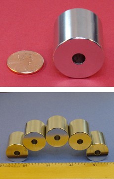
One powerful magnet could "be" the motor:
http://www.kjmagnetics.com/proddetail.asp?prod=DX0X0DIA
This is a watch patent which combines the Lavet motor and the Cam idea.
.

.
.
This is a Lavet type motor rotating through one revolution.
Notice how the color changes within the magnet when it's in the two positions where the poles are getting the most access to iron. This slight bias is all that is needed to create the conditions to start up the motor.
.
.
The grooves set at 45 degree angles make sure the magnet settles off the centerline. When the power pulse comes on the magnet "flips" and can't get jammed because it's off the centerline. It then settles into the next and so on.
If one doesn't want any sensoring you can get away without it.
.
.
Naturally the first thing you want to do is make the Lavet motor as high performance as possible for the lowest weight. To do this I realized the side positions which limit flux transfer around the magnet are the ideal place to put the copper coils since that's an unused area. You then wrap everything up as tightly as possible to reduce iron requirements. The copper-to-iron ratio is great, lot's of copper, so low resistance and heat.
The motor has 25% of the time when there is no power. These are from 90 degrees (up) to the 135 degree position to the left and on the reverse positions too. So 45 degrees plus 45 degrees means 90 degrees go idle or have reduced torque.
The rest is either a power stroke or if the magnet is strong enough you can let the magnet do all the work. Saturation of the iron is very easy with Neodymium magnets so the whole thing has very high cogging behavior.
In something like a watch the power pulse can exactly be delivered to overcome the cogging force and so very efficient energy usage is possible.
The beginning of the power stroke actually attempts to fight the magnet which means you are applying power to reverse the flux that already exists. This is good in that you are avoiding saturation because you are inhibiting an already nearly saturated iron. What this means is that this type of motor tends to deliver a constant power. So if you want several horsepower in a motor with a smooth delivery this motor is not good at that. However, if you reduce the strength of the magnet you could get better midrange. It all comes down to your magnet-to-iron-saturation ratio... too much magnet and you are forced to full power all the time. (it's like too much cogging)
This would work well for a fairly constant 250 watt mid-drive.
It might be interesting to look into weaker magnets since iron saturation occurs very easily. (or different geometries)
.
.
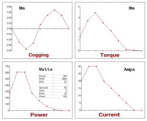
Torque is limited by iron because of saturation. Unless you want to add a lot of excess weight you would need a power pulse that was actually shaped to match the conditions within the Lavet motor. Power applied can be greater in the beginning because you are reversing the flux circulation, but once the flow changes direction and picks up speed it saturates. So a "bang" pulse that tapers is best.
This is a half revolution going from one cogging point to the next.
The last segment (@ 150 degrees) is the "idle zone" where the only torque is from the magnet-to-iron interaction that creates cogging. More "skew" actually increases this "idle zone" size, so it might be wise to see how little "skew" you can get away with.
Torque for 270 watts is around 2-3 Newton Meters which would scale up with the gear reduction (say 30-to-1) to around 60-90 Nm which is where it needs to be.
This idea seems workable and if the power pulse were optimized for the motor geometry efficiency would be good. Very few moving parts, so the only friction and wear would be between to cam and the sprocket.
I'm assuming this magnet:
http://www.kjmagnetics.com/proddetail.asp?prod=RX04X0DIA
.
.
...looks like my hole size was too small.
The magnet is only 3.19 ounces (90.5 g) but the iron and copper would be about 3-4 pounds, so the whole thing would be about 5-6 pounds with sprocket. I'd mount it on the left side and include a freewheel, then use a PAS system for throttle.
.
.
Trying a different gif animation maker... hmmmm...
The data looks good.
Weight is less than I thought and the iron is just one pound. Copper would add another pound and the magnet and other mountings would add a third, so the whole thing should be more like three pounds for 250 watts of power.
.
.
Another idea... another animated gif maker...
.
.
.
https://endless-sphere.com/forums/viewtopic.php?f=30&t=72692#p1097701
.
.
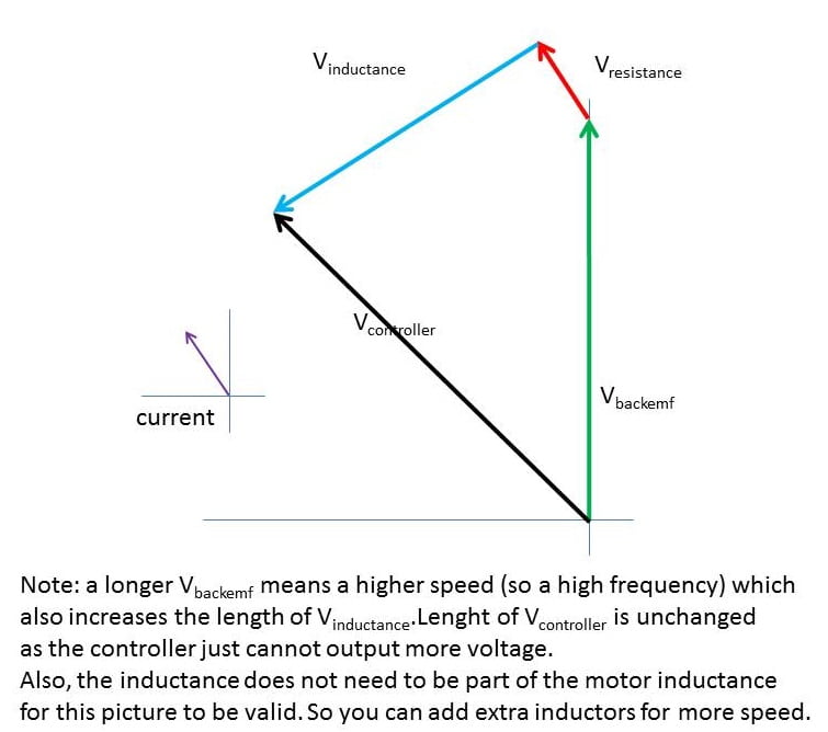
This is from a very interesting discussion on endless-sphere led by Lebowski about a way to significantly increase field weakening in a DC brushless motor by adding external inductors. Basically the additional inductors allow a kind of electronic advance. Adding external inductors will increase resistance, so there is an efficiency penalty to doing this, but the added rpm could mean being able to achieve a top speed you otherwise would be unable to reach.
.
To mentally comprehend what is happening you need to see motor energy as a kind of spring and voltage as the force you can apply. By adding inductance you increase the holding capacity of that spring and by beginning the voltage earlier (advancing the timing) it allows the same voltage to act longer to build up the motor energy thus delaying the torque maximum. But this is wasteful in the sense the external inductors don't "do" anything other than add resistance. Normally the motor inductance contributes to adding torque to the motor output, but in this case it's wasted.
.
However, if you have something like a hub motor that is limited to 20 mph by design then adding these external inductors could possibly increase top speed to 30 mph with minor losses in performance. It's a stealthy way to get more top speed without having to add more voltage. One wonders if the controller itself could provide this feature since those external inductors could be built into the controller.
.
This exposes the inductance <--> voltage dynamic of the electric motor.
.

.
.
.
https://en.wikipedia.org/wiki/Gyrator
.
A gyrator can be used to transform a load capacitance into an inductance. At low frequencies and low powers, the behaviour of the gyrator can be reproduced by a small op-amp circuit. This supplies a means of providing an inductive element in a small electronic circuit or integrated circuit. Before the invention of the transistor, coils of wire with large inductance might be used in electronic filters. An inductor can be replaced by a much smaller assembly containing a capacitor, operational amplifiers or transistors, and resistors. This is especially useful in integrated circuit technology.
.
So it could be possible to include this circuit into the controller to simulate an inductor without needing to actually have one.
It also seems possible to make this simulated inductor behave as appearing to have a variable inductance.
Based on how the circuit works I'd think you could achieve high simulated inductance while only getting hit with low resistance. This would mean you could achieve the desired field weakening (timing advance) with far less loss of efficiency. At least that's my "guess".
You might need to replace the op-amp with a MOSFET somehow, or there might be some way to modify the controller circuit itself to incorporate this "side current" of external inductance. Looks like an interesting thing to study.
It seems a little like the "startup capacitor" idea that shifts things out of phase.
.

.
Probably the better way to achieve higher motor rpm is to switch from the Buck (only) converter to something that is both Buck and Boost. There are numerous designs, but the Cuk seems most highly regarded:
.
https://en.wikipedia.org/wiki/Ćuk_converter
.
.
Power is always volts times amps, so as the voltage rises (above pack voltage) the amperage would decline in proportion. Doubling voltage is entirely within reason and efficiency can be in the 94% range if done correctly. And in some way these two techniques (field weakening and voltage boosting) are doing the same thing in that they temporarily store energy in a capacitor (or an inductor) before feeding it to the motor. A direct comparison of efficiency might show their outcomes as being similiar.
.
The difference would be that in field weakening you are increasing energy on each individual phase on their own unique cycle. With a buck-boost converter you are raising the pack voltage overall. The question would be if there is some performance advantage to dividing up the phases.
.
Pages