Cube magnets are easier to deal with as far as preventing unwanted slipping compared to a smooth cylinder. Also, the magnetic flux is very focused in one direction (North to South) but there is next to nothing on the sides. The cogging behavior is actually even more extreme.
And the shape of the curves are designed to follow the oddness of the cubes magnetic flux lines.
By adding steel on the North and South sides of the cube magnet you gain an enormous increase in cogging torque. Not only is it bigger, but it also smooths out some unevenness that existed in the version without steel ends.
It's spinning in the proper direction for power application. The upper right to lower left North / South position is the rest position. In the middle there is a point where you cross zero cogging, but that would always coincide with your power stroke so it's not a possible resting point.
And check out how little flux is on the sides of the cube. This basically focuses 100% of a really monster magnet into use. At 4 ounces this cube is doing everything. I don't think people fully realize how truly insanely powerful magnets have become and how that might be exploited. This exploits the little monster magnet fully.
.
.
First, the cogging shown represents only 180 degrees of motion, so stick two together to create 360 degrees.
There are small RC motors that barely achieve 0.5 Nm of Torque even when running under power, so cogging of 0.5 Nm is severe. Peak Torque should be in the range of 4 or 5 Nm depending on the practicalities of copper fill and applied current.
Size, shape, magnet fill all decide power output potential, but this seems good.
5 Nm with a gear reduction of 2-to-40 means 20 times increase in Torque or 100 Nm, but that only counts as peak Torque, so figure about half that or less on average.
Also, let me add that power actually works against the flux of the cogging. So the cogging itself nearly saturates the silicon steel and power is applied to reverse this and bring flux to zero or beyond. So if you wanted you can push the silicon steel from one extreme to the other to maximize power output. But you can also run at lower power levels and achieve less iron loss because the iron is only doing half of a hysteresis loop. (a good thing)
A mimimal level of energy would be required just to get this Lavet Motor to run because the high cogging levels require a high enough power to overcome the cogging.
With this animation I'm testing the limits of Iron Saturation.
At first the Lavet Motor has no current applied and the cogging torque of this position is actually backwards from what it will be going forwards. My estimate is that it takes less than 25 watts to get the motor started. Then as you increase current the flow increases until it saturates and despite throwing a lot more energy at the motor you get next to nothing more from it.
Maximum Efficiency appears at about 4-5 Nm of Torque.
One of the strange things about toying with these motor ideas for a long time is that you notice things as you go along.
A thing I've noticed is that the modern Neodymium magnets are stronger than the surrounding silicon steel can really handle.
So it makes you wonder about present designs.
If the magnets these days are the strongest "surplus" magnetic flux implementers then they should be used closest to the weakest link in the flux flow which is at the air gaps.
By placing massive highly powerful (N52) Neodymium blocks onto the rotor you cross the air gaps with ease because even with no activity in the stator you nearly saturate the silicon steel just with the magnets.
The typical CSIRO design is more focused on efficiency so it actually doesn't use silicon steel and uses copper by itself while allowing the magnets to spin outside of the copper.
.
.
This kind of design seems better able to use the powerful Neodymium magnets and generate more Torque at lower rpm.
The Lavet motor suffers from the fact that overly powerful magnets demand ever more silicon steel to prevent saturation. So you run into power-to-weight issues because the silicon steel gets too big. The Lavet motor can be made to be very efficient as far as power is concerned, but it's not the best as far as power-to-weight ratio and the problem is silicon steel saturation. Find a silicon steel capable of 2.0 Teslas without saturation and losses and you fix the problem.
This was one of those "gotta get around to it" things to try.
It's a standard RC motor configuration with the LRK winding pattern.
12N 14P LRK
Notice how the colors switch from light to dark, that's supposed to reflect which way the flux is flowing. (current changing from positive to negative)
The magnetic flux actually goes through seven rotations for every full rotation of the outer magnets.
The first thing you notice is how much less saturation occurs in the outer magnet holding shell in DLRK compared to LRK because in DLRK there is a "push pull" taking place. This means the shell can be made thinner which saves weight.
The DLRK also produces slightly more torque than the same energy applied in LRK so overall the DLRK is a better winding pattern as far as I can tell.
Color reversal in the animation means current reversal.
I had left the idea of using a Sprag Clutch somewhat dormant because I really couldn't think of a good way to drive it. Then I stumbled upon this very, very crude video:
.
.
He explains his logic at about two minutes into the video.
Basically he realizes that magnet technology has advanced dramatically while the medium that conducts magnetic flux... the silicon steel... has remained unchanged.
And this I see too. We tend to use very little magnet in our motor designs because if you use too much the silicon steel tends to saturate. (the Lavet motor suffers from this problem)
So the thought is to force a Battle between Magnet and Steel.
.
.
Unfortunately after doing a quick dynamic test I remembered why this is a bad idea.
The problem is that you begin with pre-stressed Silicon Steel. Before you do anything with the Copper in an attempt to generate a Force the fields are stable and line up nicely. (initially the field is near 0.4 Teslas) But as you increase the Current the magnetic flux wants to shift in one direction. It wants to be a Parallel Path type motor and throw the flux in one way or the other.
So what happens?
One side completely saturates and the other is being forced into reversal so one magnet has been negated and it's Silicon Steel is barely used.
Basically you can tell a good motor design when the color doesn't change much based on a FEMM simulation because that means there are no extremes of flux causing saturation.
The animation of the RC type motor previously was very smooth and so you can see efficiency best when it's run as an animation. (those seem to be the accepted best performers)
The bottom line... the Battle of Magnets and Steel doesn't work as one thinks because in order to attain power the Steel must show a bias and when it does one side saturates. Always do dynamic testing.
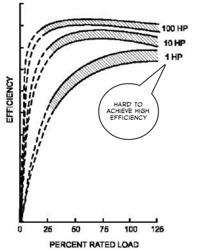
The first problem one encounters with the Induction Motor as a concept is that smaller motors generally perform poorly across the entire power spectrum.
.
.
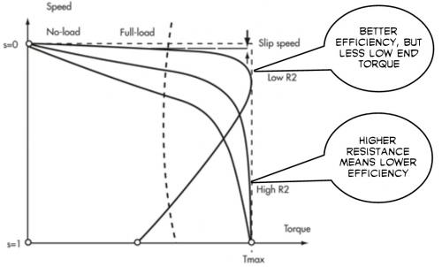
Your first design choice is whether to choose a squirrel cage material that has either a higher or lower resistance. If you choose low resistance then you can achieve the highest possible efficiency. The bigger your motor the more low resistance material you can use without "penalty" so this is why the bigger motors become more efficient.
.
"One wants rotor mass, but not to have to pay for it electrically."
.
Using higher resistance rotor material could allow for impressive torque in a relatively light weight small Induction Motor, but don't be surprised if efficiency is down in the 50% range much of the time. The non-intuitive thing here is that the smaller and more overworked this motor becomes the better it performs.
.
.
Based on ebike laws which set strict limits on power usage the idea of wasting a significant amount of energy due to efficiency losses seems like a bad idea, but if you change your thinking about those laws to redefine them as power output (rather than input) this might be a way to get that hub motor to be able to handle a difficult hill. It really adds a degree of flexibility that until now was only provided by a mid-drive and multispeed gearing.
So the logic would be to build a very small Induction Motor hub motor with likely high resistance rotor elements then use the controller to calculate legal compliance so that maximum permitted output is always available. One then "cheats" a little at the lower speeds to give some extra hill climbing benefit. The law will really only concern itself with the bike staying below the speed limit and likely look the other way on low end torque.
The guys actually fiddling around with the idea aren't even contemplating laws... so this is a "wild wild west" kind of project happening elsewhere. (like in the old days)
The idea is to really bulk up the magnets and in doing so be able to have very large air gaps in between the magnets and the inner and outer stators while still maximizing flux usage in the stators. The total air gap is about six times larger compared to the standard DLRK (both sides of the magnet) and yet iron saturation is still occurring. This gives an idea how overmatched these magnets are to the iron.
Push-pull occurs on both sides of the magnets.
The above animation is the radial version of this type of motor.
.
.
Doing this as an axial flux motor would be better, but with FEMM in two dimensions there is no way to do it. I could simulate a linear equivalent however.
Torque is roughly four times as much compared to the standard DLRK design for the same input power, but that's an unfair comparison because the second stator doubles the copper as well as the silicon steel. (so the motor is twice as big overall) The inner stator is the same for both animations.
.
Q: Is the QLRK radial version an Inrunner or an Outrunner?
A: I'd say it's both. (both stators are fixed, only the magnets move)
People often think of a 6 Phase motor as a way to get smoother performance.
This wasn't my motivation...
I had this idea of a "sparse motor" where space was plentiful, but there was a desire to reduce weight while also gaining high levels of torque.
The thinking was that the silicon steel is heavy, but the magnets are relatively light weight, so if you expand the motor dimensions and roughly double the magnets then you can gain torque without adding the weight.
6 Phases work very well.
In a 3 Phase motor two phases are always on and one is off so you get:
2 / 3 = 66% of the coils are active at any time.
With the 6 Phase motor you do things differently:
5 / 6 = 83% of the coils are active at any time.
...so you use the coils 17% more with 6 Phase.
.
This magnetic field rotates a total of 11 times around for every revolution of the magnets. This compares to 7 times for a regular 12N, 14P motor.
You will have to use your imagination to see this motor as axial flux.
This is somehow more visually pleasing because the magnetic field spins in the same direction as the magnets, though I'm not sure if that actually provides any extra benefit.
The magnetic field now spins 13 times for each motor revolution.
It's also packing more magnets into the same circumference.
As a "sparse motor" this could achieve higher power-to-weight ratios because silicon steel is very heavy compared to the magnets. Cost would be higher because you are using an excess of magnets.
Will have to do a linear test (simulate an axial flux design) to see how much torque is possible.
When space limitations are not an issue but large torque is desired this might be a good way to go.
Fiddling with higher phase numbers makes you wonder "where can this go"?
Assuming you use the fractional type motor layout and you use a configuration that maximizes coil usage there is an increase in usage with increasing phase numbers.
Since weight in the form of coils and iron is the biggest weight concern, if you increase the phase number to 20 you would be getting 95% usage from that weight. That's really good.
So let's go back to the Induction Motor idea that was brought up earlier.
What is an Induction Motor?
Well, the simple answer is a magnetic field is passed through some metal that reacts and creates it's own field but with an element of slip involved. As the load declines and the driven metal increases it's rotational speed the two become more synchronized. An Induction Motor is like a magnetic clutch.
To simulate this we create our own magnetic clutch with a big rotating permanent magnet linked to the motor axle. In effect this is like adding variable gear ratios, but you do waste torque because slip creates heat.
The idea is so simple there is little to explain, but this video sums it up:
.
.
This would be a type of Hysteresis Clutch.
Easy to make and if mounted with an RC motor would soften starting torque issues.
Okay, this is pretty much the extreme of phase number increasing. Beyond 19 phases and you gain nothing in adding more.
At this point your resource utilization is about 95%.
A regular Three Phase motor uses just about two thirds or 66% so you are looking at a jump from 66% to 95%.
Notice how as the only inactive phase rotates around it skips the phase direction forward as it goes. Red represents forward current in the coils and Green represents negative current. Trying to represent 19 phases with colors in both positive and negative would have been too dificult.
So understand that every coil is a phase.
The magnetic field rotates once for each magnet, so 20 times per motor revolution.
.
How might someone build such a controller to have 19 phases?
Well, with 19 phases the phase currents will be small. Assume you want 750 watts of power at 20 volts then each phase requires:
750 watts / 19 phases = 40 watts
40 watts / 20 volts = 2 amps
...so if you only need 2 amps per phase you starting thinking of the possibility of an integrated circuit design. What if you could just print a circuit board with everything in it and then only worry about the 19 phase wires attaching to the motor?
When power-to-weight is a high priority this makes sense to consider.


.
Still fiddling around with Lavet Motor designs.
Cube magnets are easier to deal with as far as preventing unwanted slipping compared to a smooth cylinder. Also, the magnetic flux is very focused in one direction (North to South) but there is next to nothing on the sides. The cogging behavior is actually even more extreme.
And the shape of the curves are designed to follow the oddness of the cubes magnetic flux lines.
There are so many ways to build a Lavet Motor.
.

.
http://www.kjmagnetics.com/proddetail.asp?prod=BX0X0X0-N52
Dimensions: 1" x 1" x 1" thick
Tolerances: ±0.004" x ±0.004" x ±0.004"
Material: NdFeB, Grade N52
Plating/Coating: Ni-Cu-Ni (Nickel)
Magnetization Direction: Thru Thickness
Weight: 4.34 oz. (122.9 g)
Pull Force, Case 1: 94.60 lbs
Pull Force, Case 2: 94.60 lbs
Surface Field: 6451 Gauss
Max Operating Temp: 176ºF (80ºC)
Brmax: 14,800 Gauss
BHmax: 52 MGOe
$34.76
Note that at just 4.34 oz it's a full 94.60 lbs of pull force.
Scary.
.
.
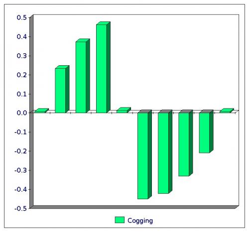
By adding steel on the North and South sides of the cube magnet you gain an enormous increase in cogging torque. Not only is it bigger, but it also smooths out some unevenness that existed in the version without steel ends.
It's spinning in the proper direction for power application. The upper right to lower left North / South position is the rest position. In the middle there is a point where you cross zero cogging, but that would always coincide with your power stroke so it's not a possible resting point.
And check out how little flux is on the sides of the cube. This basically focuses 100% of a really monster magnet into use. At 4 ounces this cube is doing everything. I don't think people fully realize how truly insanely powerful magnets have become and how that might be exploited. This exploits the little monster magnet fully.
.
.
First, the cogging shown represents only 180 degrees of motion, so stick two together to create 360 degrees.
There are small RC motors that barely achieve 0.5 Nm of Torque even when running under power, so cogging of 0.5 Nm is severe. Peak Torque should be in the range of 4 or 5 Nm depending on the practicalities of copper fill and applied current.
Size, shape, magnet fill all decide power output potential, but this seems good.
5 Nm with a gear reduction of 2-to-40 means 20 times increase in Torque or 100 Nm, but that only counts as peak Torque, so figure about half that or less on average.
Also, let me add that power actually works against the flux of the cogging. So the cogging itself nearly saturates the silicon steel and power is applied to reverse this and bring flux to zero or beyond. So if you wanted you can push the silicon steel from one extreme to the other to maximize power output. But you can also run at lower power levels and achieve less iron loss because the iron is only doing half of a hysteresis loop. (a good thing)
A mimimal level of energy would be required just to get this Lavet Motor to run because the high cogging levels require a high enough power to overcome the cogging.
.
.
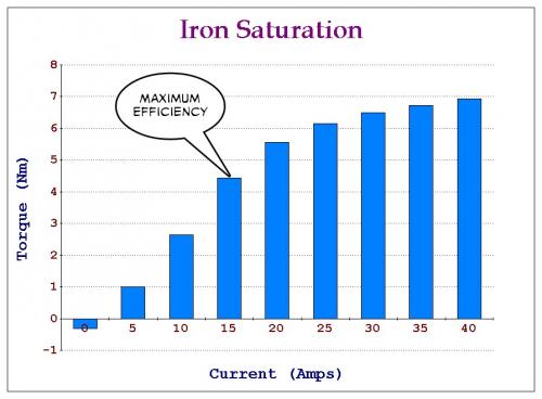
This animation is a little different.
With this animation I'm testing the limits of Iron Saturation.
At first the Lavet Motor has no current applied and the cogging torque of this position is actually backwards from what it will be going forwards. My estimate is that it takes less than 25 watts to get the motor started. Then as you increase current the flow increases until it saturates and despite throwing a lot more energy at the motor you get next to nothing more from it.
Maximum Efficiency appears at about 4-5 Nm of Torque.
.
.
.
One of the strange things about toying with these motor ideas for a long time is that you notice things as you go along.
A thing I've noticed is that the modern Neodymium magnets are stronger than the surrounding silicon steel can really handle.
So it makes you wonder about present designs.
If the magnets these days are the strongest "surplus" magnetic flux implementers then they should be used closest to the weakest link in the flux flow which is at the air gaps.
By placing massive highly powerful (N52) Neodymium blocks onto the rotor you cross the air gaps with ease because even with no activity in the stator you nearly saturate the silicon steel just with the magnets.
The typical CSIRO design is more focused on efficiency so it actually doesn't use silicon steel and uses copper by itself while allowing the magnets to spin outside of the copper.
.
.
This kind of design seems better able to use the powerful Neodymium magnets and generate more Torque at lower rpm.
The Lavet motor suffers from the fact that overly powerful magnets demand ever more silicon steel to prevent saturation. So you run into power-to-weight issues because the silicon steel gets too big. The Lavet motor can be made to be very efficient as far as power is concerned, but it's not the best as far as power-to-weight ratio and the problem is silicon steel saturation. Find a silicon steel capable of 2.0 Teslas without saturation and losses and you fix the problem.
.
.
This was one of those "gotta get around to it" things to try.
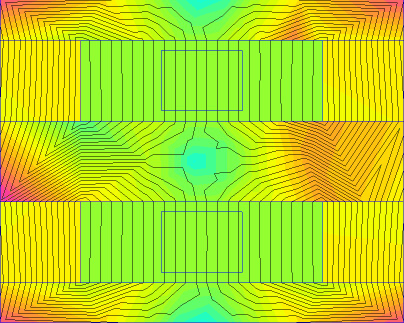
It's a standard RC motor configuration with the LRK winding pattern.
12N 14P LRK
Notice how the colors switch from light to dark, that's supposed to reflect which way the flux is flowing. (current changing from positive to negative)
The magnetic flux actually goes through seven rotations for every full rotation of the outer magnets.
.
.
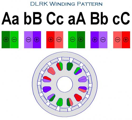
12N 14P DLRK AabBCcaABbcC
And a little guide to the color scheme:
.
.
The first thing you notice is how much less saturation occurs in the outer magnet holding shell in DLRK compared to LRK because in DLRK there is a "push pull" taking place. This means the shell can be made thinner which saves weight.
The DLRK also produces slightly more torque than the same energy applied in LRK so overall the DLRK is a better winding pattern as far as I can tell.
Color reversal in the animation means current reversal.
.
.
I had left the idea of using a Sprag Clutch somewhat dormant because I really couldn't think of a good way to drive it. Then I stumbled upon this very, very crude video:
.
.
He explains his logic at about two minutes into the video.
Basically he realizes that magnet technology has advanced dramatically while the medium that conducts magnetic flux... the silicon steel... has remained unchanged.
And this I see too. We tend to use very little magnet in our motor designs because if you use too much the silicon steel tends to saturate. (the Lavet motor suffers from this problem)
So the thought is to force a Battle between Magnet and Steel.
.
.
Unfortunately after doing a quick dynamic test I remembered why this is a bad idea.
The problem is that you begin with pre-stressed Silicon Steel. Before you do anything with the Copper in an attempt to generate a Force the fields are stable and line up nicely. (initially the field is near 0.4 Teslas) But as you increase the Current the magnetic flux wants to shift in one direction. It wants to be a Parallel Path type motor and throw the flux in one way or the other.
So what happens?
One side completely saturates and the other is being forced into reversal so one magnet has been negated and it's Silicon Steel is barely used.
Basically you can tell a good motor design when the color doesn't change much based on a FEMM simulation because that means there are no extremes of flux causing saturation.
The animation of the RC type motor previously was very smooth and so you can see efficiency best when it's run as an animation. (those seem to be the accepted best performers)
The bottom line... the Battle of Magnets and Steel doesn't work as one thinks because in order to attain power the Steel must show a bias and when it does one side saturates. Always do dynamic testing.
.
.
Endless-sphere has an interesting discussion about an Induction Motor project:
https://endless-sphere.com/forums/viewtopic.php?f=30&t=73164
The first problem one encounters with the Induction Motor as a concept is that smaller motors generally perform poorly across the entire power spectrum.
.
.
Your first design choice is whether to choose a squirrel cage material that has either a higher or lower resistance. If you choose low resistance then you can achieve the highest possible efficiency. The bigger your motor the more low resistance material you can use without "penalty" so this is why the bigger motors become more efficient.
.
"One wants rotor mass, but not to have to pay for it electrically."
.
Using higher resistance rotor material could allow for impressive torque in a relatively light weight small Induction Motor, but don't be surprised if efficiency is down in the 50% range much of the time. The non-intuitive thing here is that the smaller and more overworked this motor becomes the better it performs.
.
.
Based on ebike laws which set strict limits on power usage the idea of wasting a significant amount of energy due to efficiency losses seems like a bad idea, but if you change your thinking about those laws to redefine them as power output (rather than input) this might be a way to get that hub motor to be able to handle a difficult hill. It really adds a degree of flexibility that until now was only provided by a mid-drive and multispeed gearing.
So the logic would be to build a very small Induction Motor hub motor with likely high resistance rotor elements then use the controller to calculate legal compliance so that maximum permitted output is always available. One then "cheats" a little at the lower speeds to give some extra hill climbing benefit. The law will really only concern itself with the bike staying below the speed limit and likely look the other way on low end torque.
The guys actually fiddling around with the idea aren't even contemplating laws... so this is a "wild wild west" kind of project happening elsewhere. (like in the old days)
.
.
QLRK - "Quad" LRK Motor
The idea is to really bulk up the magnets and in doing so be able to have very large air gaps in between the magnets and the inner and outer stators while still maximizing flux usage in the stators. The total air gap is about six times larger compared to the standard DLRK (both sides of the magnet) and yet iron saturation is still occurring. This gives an idea how overmatched these magnets are to the iron.
Push-pull occurs on both sides of the magnets.
The above animation is the radial version of this type of motor.
.

.
Doing this as an axial flux motor would be better, but with FEMM in two dimensions there is no way to do it. I could simulate a linear equivalent however.
Torque is roughly four times as much compared to the standard DLRK design for the same input power, but that's an unfair comparison because the second stator doubles the copper as well as the silicon steel. (so the motor is twice as big overall) The inner stator is the same for both animations.
.
Q: Is the QLRK radial version an Inrunner or an Outrunner?
A: I'd say it's both. (both stators are fixed, only the magnets move)
.
.
6 Phase - 12N, 22P
People often think of a 6 Phase motor as a way to get smoother performance.
This wasn't my motivation...
I had this idea of a "sparse motor" where space was plentiful, but there was a desire to reduce weight while also gaining high levels of torque.
The thinking was that the silicon steel is heavy, but the magnets are relatively light weight, so if you expand the motor dimensions and roughly double the magnets then you can gain torque without adding the weight.
6 Phases work very well.
In a 3 Phase motor two phases are always on and one is off so you get:
2 / 3 = 66% of the coils are active at any time.
With the 6 Phase motor you do things differently:
5 / 6 = 83% of the coils are active at any time.
...so you use the coils 17% more with 6 Phase.
.
This magnetic field rotates a total of 11 times around for every revolution of the magnets. This compares to 7 times for a regular 12N, 14P motor.
You will have to use your imagination to see this motor as axial flux.
.
.
6 Phase - 12N, 26P
.
This is somehow more visually pleasing because the magnetic field spins in the same direction as the magnets, though I'm not sure if that actually provides any extra benefit.
The magnetic field now spins 13 times for each motor revolution.
It's also packing more magnets into the same circumference.
As a "sparse motor" this could achieve higher power-to-weight ratios because silicon steel is very heavy compared to the magnets. Cost would be higher because you are using an excess of magnets.
Will have to do a linear test (simulate an axial flux design) to see how much torque is possible.
When space limitations are not an issue but large torque is desired this might be a good way to go.
.
.
Fiddling with higher phase numbers makes you wonder "where can this go"?
Assuming you use the fractional type motor layout and you use a configuration that maximizes coil usage there is an increase in usage with increasing phase numbers.
Since weight in the form of coils and iron is the biggest weight concern, if you increase the phase number to 20 you would be getting 95% usage from that weight. That's really good.
This guy explains:
.
.
.
So let's go back to the Induction Motor idea that was brought up earlier.
What is an Induction Motor?
Well, the simple answer is a magnetic field is passed through some metal that reacts and creates it's own field but with an element of slip involved. As the load declines and the driven metal increases it's rotational speed the two become more synchronized. An Induction Motor is like a magnetic clutch.
To simulate this we create our own magnetic clutch with a big rotating permanent magnet linked to the motor axle. In effect this is like adding variable gear ratios, but you do waste torque because slip creates heat.
The idea is so simple there is little to explain, but this video sums it up:
.
.
This would be a type of Hysteresis Clutch.
Easy to make and if mounted with an RC motor would soften starting torque issues.
.
.
19 Phase : 19N - 20P
.
Okay, this is pretty much the extreme of phase number increasing. Beyond 19 phases and you gain nothing in adding more.
At this point your resource utilization is about 95%.
A regular Three Phase motor uses just about two thirds or 66% so you are looking at a jump from 66% to 95%.
Notice how as the only inactive phase rotates around it skips the phase direction forward as it goes. Red represents forward current in the coils and Green represents negative current. Trying to represent 19 phases with colors in both positive and negative would have been too dificult.
So understand that every coil is a phase.
The magnetic field rotates once for each magnet, so 20 times per motor revolution.
.
How might someone build such a controller to have 19 phases?
Well, with 19 phases the phase currents will be small. Assume you want 750 watts of power at 20 volts then each phase requires:
750 watts / 19 phases = 40 watts
40 watts / 20 volts = 2 amps
...so if you only need 2 amps per phase you starting thinking of the possibility of an integrated circuit design. What if you could just print a circuit board with everything in it and then only worry about the 19 phase wires attaching to the motor?
When power-to-weight is a high priority this makes sense to consider.
.
.
Concepts for eBike Propulsion 2 thread created.
.
For a short time the first post of this thread was offline due to some technical difficulty and so I created a second thread.
The problem has been fixed, but I'm going to shift to the new thread anyway since this one is very long.
Think of it as "Volumes I and II".
If some parallel activity occurs that's okay too.
No problem.
.
Pages