Even at zero frequency the difference between a Solid winding pattern and one shaped like a Tube is significant.
In the nine 20 AWG wire configuration with three sets of three per row the center wire is seriously dampened compared to the one's on the edges. By my estimate the center wire has an apparent resistance that is 40% higher than the others.
You can see the magnetic flux summary here:
.
.
There is a difference between "Equal Current" and "Equal Power" because the added resistance of the Solid wind requires a higher voltage (as in BackEMF) to drive the current through. (this gets exponentially worse at high frequency)
When you compare "Equal Power" you get this percentage difference in magnetic flux:
.
.
So winding patterns are very important.
I've read that for high frequency transformers they do not use more than one layer of windings because anything beyond that is a total waste.
.
This means that big thick coils are a terrible design.
.
When designing motors the closer to 1 mm (20 AWG diameter) your winding bundles are in thickness the better because that is the skin effect up to 1 kHz.
Any winding bundle of a thickness greater than about a single strand of 20 AWG wire is too thick and wasteful in both power and in weight.
This concept of a "Hollow Tube" gets very tricky when applied to motor windings because you have to wonder how you would introduce the hollow center while still being able to do multiple series windings in your pattern. Keep in mind that in the animation those wires go directly into the page so they are all parallel with each other, but just given a tube shaped pattern.
In FEMM you can set your Flux Density so that it displays colors that are relevant to what you are looking at.
Normally the Skin Effect and it's contribution to BackEMF is so far below the Flux Density of Silicon Steel you just don't see it. The BackEMF at zero frequency can only be seen if you are looking down in the 0.01 Tesla range.
So the animation cycles through the low spectrum of Flux Density in the range set as zero on one end and from 0.0005 Tesla to 0.01 Tesla on the other.
Normally the Flux passing through the Silicon Steel is near or above 1.0 Tesla.
What you begin to realize is that a coil is like a vortex where all Flux gets emptied outward. Everywhere else there is some Flux, but next to nothing inside the active parts of the coil.
The Skin Effect is that within that vortex any wire you put in there will experience an effect that is not to the benefit of that wire.
In short, you want tubes and not solid bundles of wires.
BackEMF cannot be eliminated because the vortex will always push things outward, but you can actually reduce it with a different mindset in the design.
You see a lot of guys playing around with Thin Flat Foil as an alternative to wire windings.
At low frequencies this seems pretty good because you always can get the edges to squeeze some current through even when the middle is acting as a BackEMF traffic jam.
But as the frequency increases (the animation goes from zero to 1 kHz) you can see that the Thin Flat Foil seems to want to fight against itself and if you look carefully there are little gaps between the Thin Flat Foil with reduced flux.
This state of complete chaos might actually produce some decent current flow, but judging by a few sample data points it's still running some very high BackEMF values.
In my opinion tubes are better than foil.
The tube shape more closly reflects what the current "wants" to follow, so as far as weight or efficiency is concerned it seems tubes are the ideal.
It's somewhat interesting to imagine combining water cooling with the design of the coil like I considered previously:
The more you learn about electricity and magnetism the more bizarre things seem to get.
Often there are tricks that can exploit things above what is obvious.
You would "think" that the ideal conductor would be a thin tube because of the Skin Effect, but actually there are ways to improve upon that.
It seems that having an opening somehow releases some flux from the interior of the tube shape and this improves performance.
At 1 MHz the square shaped area (which is exactly the same amount of copper as the tube) produces a real power that is 27% higher. (as measured in FEMM)
Compared to a solid bundle of copper wires and at high frequency the difference could be as high as 70%.
The animation begins with a solid copper wire with a diameter of 1/4" which represents the ordinary coil cross section in many electric motors. (per winding slot)
The frequency is 1 kHz throughout the entire animation which is the maximum that most of our motors ever reach and the current is the same at a constant 500 amps which is very moderate for that cross section of wire. It's roughly equivalent to 50 turns of 20AWG wire in cross section, so just 10 amps current per wire.
At first the wire is solid, but then it becomes a tube of thinner and thinner thickness while retaining the exact same cross section area, so it's an apples to apples comparison.
As the tube gets bigger and thinner the Voltage Drop Declines and the reduction is represented by the percentage in the upper right hand corner.
What does this mean?
It means that BackEMF will be Reduced which means you could either spin the motor 25% faster or redesign the kV to be lower so that it has 25% more torque. (however, since the Skin Effect issue is more significant at higher frequencies you might just accept a higher top speed)
The question of whether BackEMF can be reduced has been answered:
.
"Yes, BackEMF can be reduced by exploiting knowledge of the Skin Effect on a conductor".
.
...what this doesn't answer is the increase in overall volume this requires and the practicality of squeezing this into a motor design, but "in principle" the basic physics is correct.
Well we know that you can reduce BackEMF if you fiddle around with the shape of your conductors, but there is a limit to how much that can achieve at low frequency. If we were dealing with frequencies in the 1 MHz range the primary issue would be reducing the skin effect because it goes nuts at those high frequencies. Most electric motors can get by at 1 kHz or less and things aren't really that bad there.
So what is BackEMF really?
The primary cause is the eddy currents caused by the skin effect inside the conductor itself.
The secondary effect is that you create an Inductor that acts like a spring that wants to spring back against your attempts at higher frequency.
I've noticed some guys playing around with a different winding scheme where they create Assymetric Windings that seem to act as if they are two Inductors. These out of phase coils are configured so that their inductance is passed forward during rotation. They have actually built these motors.
This might violate some basic law of physics, but until I do some FEMM simulations I will not be able to say for sure.
This is different than 12N,14P RC motors that do a kind of electrical gear reduction in their windings. Those RC motors are still behaving as classic inductors.
So I'll fiddle with it and see if there's anything to the idea.
.
.
...the idea seems similiar to a Shaded Pole motor because one phase interacts with the next.
Okay, I think I'm beginning to comprehend the underlying theory upon which this Asymmetric Motor idea rests.
An Inductor will build up it's magnetic field because as currents travel through a conductor (copper wire) the skin effect creates eddy currents that spin in perpendicular directions creating their own magnetic field. This does nothing but store energy into something that is wasteful. This wasteful perpendicular energy goes by the name BackEMF and is Lenz Law. But an Inductor can also be seen as like a battery or capacitor because other than resistive losses the energy stored goes "somewhere" and could actually be captured.
The "Flyback Diode" is an example of how the controller deals with this rebounding of energy when the switch is disconnected on an Inductor.
.
.
So the Asymmetric Wound Motor with Dual Commutators allows the BackEMF to recirculate back into the motor again, but it's reintroduced on the opposite phase. In effect the Asymmetric Wound Motor attempts to take the place of the Flyback Diode. But apparently you could also just redirect that energy elsewhere too, so it behaves like a motor / generator in two halves.
The net effect should be a motor which behaves the same as a traditional winding but with significantly less BackEMF which means you require less voltage to achieve the same maximum rpm. This would permit lower kV motor winds and should improve efficiency while reducing current requirements. Lower kV means less current required, however, the concept of "kV" is itself built into the standard motors that lack a Flyback Diode / Asymmetric Winding philosophy so it would be interesting to see how the math might work out.
As a circuit a Symmetric motor can be seen as an Inductor and a Resistor.
.
.
With an Asymmetric motor you are splitting the Inductor in two and the effect is to retain that BackEMF energy and transfer it between the Inductors.
This gives the appearance of lower BackEMF because on each switch in polarity you are getting an extra boost as the two Inductors interact with each other.
From the circuit perspective this is really easy to understand.
Just looking at the circuit results it appears that a 10% improvement in coil "on" time would occur and this will mean less advance will be required at higher frequencies. This effect gets more extreme as the frequency increases.
.
The Asymmetric concept makes BackEMF work with the motor rather than against it.
So a connection of two separate ideas just "linked up" in my head.
The idea of the Asymmetric motor is to balance two Inductors so that as they function in parallel the BackEMF will cancel each other out. In effect it's recycling energy rather than fighting against it.
The other idea is the concept of "parallel paths" of magnetic flux that are "switched" between those two optional routes much like a transistor. With a magnet as the driving force for magnetic flux (rather than brute force originated by the copper coils) the energy to switch back and forth is very low.
In the animation I'm switching flux paths at a cost of a watt and that's a massive three inch wide hunk of one inch deep silicon steel.
.
What if a motor used BOTH parallel flux paths AND BackEMF recycling?
.
And why not throw in reduced Skin Effect coil configurations too?
I want to revisit the John Vranish Gear Bearing idea.
Looking at the abandoned prototype that the E-RAM system attempted there are some things that stand out about their base configuration. First, it's not a "Gear Bearing" at all but an ordinary compound gear reduction using some ordinary bearings with a pin physically restraining it. This introduces some wiggle into the design. Then you add that the outer shell is quite large and thin so it's naturally going to resonate like a bell making noise louder.
.
.
...I'm still of the belief that a true John Vranish Gear Bearing has the potential for the performance that is desired.
The teeth in the upper and lower halves are shifted angularly, relative to each other, by precisely a half-tooth interval. This gear bearing meshes with a copy of itself. The upper and lower teeth are beveled and partly interdigitated where they meet. The contact between the beveled surfaces of the upper and lower teeth provide a thrust-bearing capability in a manner similar to that of the contact between the crowns and rollers of the roller gear bearings. Moreover, a planetary assembly containing phaseshifted gears holds itself together in a manner similar to that of an assembly containing roller gear bearings as described above.
.
...so there are subtle "secrets" that others are likely unaware of. The compact nature of the Gear Bearing design coupled with a thick outer shell and "secrets" to tooth patterns could knock the noise down significantly.
I'm not willing to write the Gear Bearing off as a solution for high powered systems seeking high power-to-weight ratios.
If the annulus is held stationary and the sun gear is used as the input, the planet carrier will be the output. The gear ratio in this case will be 1/(1 + Na/Ns). This is the lowest gear ratio attainable with an epicyclic gear train.
.
Ratio = 1 / (1 + 36/12) = 0.25 or 4-to-1
.
.
Assuming you start with a 12 tooth Sun gear in a planetary gear configuration your options are fairly limited as far as reduction. Standard reduction would be about 4-to-1 and the higher end is only 5-to-1.
This would be that 4-to-1 design:
.
.
Then you match that to a specifically designed Left Side Crank mounting which would include a freewheel to allow the cranks to operate without power.
.
.
Your output would be:
Sun 12 --> Planet 12 --> Annulus 36 : Ratio 4-to-1
Drive gear 12 --> Big Gear 120 : Ratio 10-to-1
Overall 4 * 10 = 40-to-1 Reduction
Motor Rpm 4000 ---> Output 100 Rpm
The funny thing is that I haven't seen this done yet in spite of how simple and light weight it would be. You would need a 20 DP 120 tooth front Left Side Crank gear to be made of aluminum most likely. Plastic might work if this is intended for 250 watt power input. Weight could be really low... like 3 lbs.
Many guys use sprockets and chains but you can't get 120 teeth in a 6" diameter even with the go kart chains (#219) so a solid gear would make this different. You can of course put holes in this 120 tooth gear to reduce weight like other front chainrings.
Sun 12 --> Planet 12 --> Annulus 36 : Ratio 4-to-1
Drive gear 4 Cam Rollers --> Big Gear 40 : Ratio 10-to-1
Overall 4 * 10 = 40-to-1 Reduction
Motor Rpm 4000 ---> Output 100 Rpm
.
.
Cam Rollers
By using Cam Rollers you increase the teeth size by a factor of three and this reduces the precision necessary and permits the use of a plastic gear which reduces noise.
Cam Rollers that are used in automobiles are very durable, but if they did wear out you could design the system so they could be replaced.
The planetary gear spins it's Planets while the Sun and Annulus remain fixed. This means the Cam Rollers could be directly attached to this spinning region. One might even design a shaft that went through both the Cam Rollers and the spinning Planet gears.
Very low friction because of the Cam Rollers. (lubrication is internal)
Okay, so I've been struggling with this animation because it takes a lot of manual move operations to do this when you haven't done it using automation.
My first error took some time to figure out.
Look at the animation above:
"How many times does the inside circle rotate per revolution?"
Three?
No... it's three minus one equals two.
It's not exactly an intuitive thing to see.
So after I realized my math was wrong I finally got to knowing the correct way to rotate all the elements involved.
Left Side Crank Motor Location
The gear reduction is:
Planetary Gear (12-12-36) does a 4-to-1 reduction.
Cam Rollers (4-40) does a 10-to-1 reduction.
Overall you get 40-to-1 reduction:
.
.
The animation was a problem.
The formulas that locate the gears are correct, but the timing of the frames makes the planets appear not to move and the sun looks like it's moving backwards.
So I'm going to have to do this again (hours of effort) using different timing in order to get it to look right. You can't easily tell what it looks like in animation until you do it.
This was created using just seven frames repeated over and over.
.
.
40-to-1 gear reduction without cycloidal or compound gearing !!!
By reducing the number of teeth by two thirds I was able to get a reasonable animation that at least gives a taste of the 40-to-1 reduction going on.
I'm going to either need to learn the FEMM scripting language or use some other tool to do it any better. This was just nine frames, but it took a couple of hours to create. Ideally this would have many more frames to make the motion appear smoother.
Anyway... 40-to-1 reduction is possible without needing either the cycloidal reduction (which creates vibration) or the compound reduction (which creates friction) so this might be the most simplified solution.
A motor could be designed so that there was a central spinning part that had magnets (Sun) and a second spinning part that had magnets. (Planets)
You could then find some fractional difference between the two so that you did something like the John Vranish Compound Gear idea where the output was defined by a slight difference in the two. (but now no friction problem)
For output you use a planetary gear that included it's own fixed Annulus.
I'll have to work on the idea more and get better animations, but it seems like high gear reduction could be built into the motor because of these Counter Rotating components.
.
.
Note how these magnets rotate opposite each other, but align as they pass, so it should be possible to introduce a coil into this to drive it from the area between them.
Something like a 6 magnet Sun and 8 magnet Planet would give:
4 - 3 = 1 ...so a 4-to-1 gear reduction, followed by the mechanical 4-to-1 gear reduction would produce 16-to-1 right off the motor.
16-to-1 can easily be dropped down after that.
You have to mentally superimpose the mechanical gears above this animation to imagine this.
I'm very near to what the Magnomatics guys have done, but I'm combining their thinking with an actual physical planetary gear making a kind of hybrid result.
So rather than searching blindly for high gear reduction I use the formulas and scan through all the likely options.
The goal is to get the Annulus to rotate in the backwards direction just slightly slower than the forward direction of the Sun so that the Planets will generate output that reflects the fractional difference much like a John Vranish style compound gear reduction but without that messy friction problem.
Seems like 8 magnets with 3 coils should work with a 2 magnet Sun.
12 and 5 might be better. (would require 5 phase controller though)
Will have to try it in FEMM.
Gear reduction of 50-to-1 or more is possible with a counter rotating motor.
Also note that odd tooth count Sun gears have higher maximum ratios than even.
When you plug this into the formula for planetary gear ratios you get:
100-to-1 reduction
Something like a Switched Reluctance motor can spin up to 10,000 rpm (very little BackEMF) which means you get an enormous amount of output torque because everything gets multiplied by 100. Output is only 100 rpm. And be reminded there is no friction issue like with a Compound Gear reduction because the gear teeth are interacting at the same speeds. Standard involute teeth profiles will be fine.
The first counter-rotating electric motor was first seen in an issued U.S. patent in the early 1900s. Over the decades several versions of counter-rotating electric motors have appeared, but many were clearly theoretical creations, some were functionally inoperable, and others mostly impractical for various obvious reasons. However, not one mention was ever made of the high efficiency/effectiveness of this type of rotational drive. Increased torque was mentioned for CR motors, but never a decrease in electrical power input relative to increased mechanical power output. Since nearly all of the versions were powered by a continuous supply of electricity, there was, apparently, no interest in conserving the amount of electricity used to power the device. The versions utilizing a battery were found in torpedoes that have an extremely short half-life, so battery life, presumably, was not a potential problem.
Last night I had one of those profound insights...
Why does Compound Planetary gear reduction suffer from high friction?
The answer is that when you drive through the Annulus gear your Planets teeth travel along a path that dives into the Annulus teeth which when under load means the teeth must scrape their way past each other before bottoming out.
The way to design a Planetary gear reducer for low friction is to drive through the Carrier because the load will only apply itself in agreement with an Involute Gear interaction:
Another way to say it is that for Planetary gearing:
"Avoid driving the Annulus in all cases."
This might mean that you choose NOT to get the counter rotation done using a Planetary gear, but having to design a counter rotating motor is probably unnecessary. So the first stage is likely a simple gear, then followed by the Planetary gear. This is important because if you just move the friction to the front end rather than the back end you haven't gained anything.
I took the generic formulas that define planetary gear ratios and solved for all six possible cases of having one part fixed and the other two in motion.
Then I added the second planetary gear where the output of one would be the input of the other while fixing the input-to-input of the original planetary gear so that there becomes just one final output.
You can see that insanely high gear reduction is possible.
But that's probably too much as all that is desired is between 30 and 70 to one final reduction.
What this does is free you up to design the planetary reduction system based on the goal of minimizing friction as your first priority, then as an afterthought dealing with the overall gear reduction which is actually rather easy to achieve.
My first discovery upon applying these formulas is that certain combinations have problems with planet spacing. If you want an equal number of planets on the two sets you need the ability to match them up as far as rotated angles.
The formula for that is 360 / (Sun + Annulus) = Spacing angle.
In this case it takes a multiplier of 16 and 15 to achieve matching 90 degree planet spacing.
Note that the friction (represented by the yellow arrows) will be low because the torque will apply at the center where the gears make contact.
Final output would be represented by the reddish arrow... and the rotation would be one turn of the Carrier for every 45 turns of the (dark red) Sun. The Sun is connected across both sets and have the same teeth and in this example spin together in the clockwise direction.
The outer rings (Annulus) are of different sizes but could be built separately and then bolted together. In fact this might be the way to package things up neatly. The outer rings rotate in the counter clockwise direction in this example.
All the teeth can be the SAME PITCH which makes buying this as generic gears rather easy.
So there you have it... 45-to-1 gear reduction with low friction.
Similiar in concept to the John Vranish design, but makes different parts fixed which should reduce friction.
I'm not a huge fan of needing two sets of planetary gears even if they have low friction simply because there are just too many teeth to maintain.
So the logic here is to use Halbach Arrays in a very exotic configuration.
The inner ring of magnets has 10 magnetic poles and a total of 20 magnets.
The outer ring of magnets has 14 magnetic poles and a total of 28 magnets.
The middle region has 12 zones of magnetic variation.
The net gear ratio when these counter rotate will be 100% rotation in one direction (assume the inside) to -10/14 in the other:
-10/14 = -5/7 = -71.4%
This can be matched with planetary gears on the order of:
Sun 52 --> Planets 12 --> Annulus 76 (-0.6842 or -68.4%)
Sun 40 --> Planets 9 --> Annulus 58 (-0.6897 or -69.0%)
Sun 36 --> Planets 8 --> Annulus 52 (-0.6923 or -69.2%)
Sun 32 --> Planets 7 --> Annulus 46 (-0.6957 or -69.6%)
...to create a gear reduction of 80-to-1 and above.
If this were done as an Ironless design you could run at high rpm without any hysteresis losses so a very, very lightweight motor could spin very fast creating large amounts of torque while being geared way down to 100 rpm output.
So magnets and iron weigh about the same, but if you use iron like this:
...you have to deal with hysteresis:
So it seems that a high rpm motor can run more efficiently if it's mostly magnets and little to no Silicon Steel. (iron)
In the animation every time you charge up the Silicon Steel it takes energy that you never get back and to make matters worse you have to erase the memory of it being charged up.
It's not that there's no competition for our motor," said Dr Howard Lovatt, part of CSIRO's original design team at CSIRO Materials Science and Engineering. "People have been trying to design a better one, but it's been ten years and they just haven't been able to do it."
CSIRO's motor is the most efficient in solar racing at 98 per cent efficiency (converting 98 per cent of its fuel - electricity generated from sunlight - into useful power). It's also extremely light: the whole wheel - tyre, motor and all - weighs 14.5 kilograms. Other in-wheel motors used in solar racing typically have energy efficiencies of less than 95 per cent and weigh twice as much, not including the wheel and tyre.
The CSIRO design which uses no Silicon Steel and all Neodymium Magnets can potentially be 98% efficient. But the solar racers have no weight worries like on an ebike where we want to be down below three or four pounds. (14.5 kg is 36 lbs)
Friction caused by gear reduction reduces efficiency by at least 3% and that's why I wanted to reduce the planetary gears to a single set to reduce friction. (98% minus 3% equals 90%-95%)
Present day mid drive motors are probably running around 70%-80% efficiency by the time you reach the rear wheel but the expanded gearing options of multispeed gearing means that overall efficiency can be sometimes better than a hub motor. (90% efficiency in optimal conditions, far less uphill... like 65%)
If you want to match the power to weight of a small RC motor, you simply need to use the iron and copper at the same rates and current densities, but configured in a geometry that provides the desired output drive torque as a function of a single stage.
Later there is this response:
You are cruising along at 45 kph on the flat. You come to a 15% gradient. What is the ratio of the difference in torque requirement, assuming you don't want to slow down?
So the simple (comical) solution would be:
"When you arrive at a hill you swap out your present motor with another that has higher torque."
In the animations below the percentage is relative gear ratio for a multispeed transmission with a range of 500%. All other parameters are of a typical mountain bike.
Eventually we get to this quote:
More acceleration than your tires can handle all the way past a speed you want to be going is where putting the drivetrains mass into copper and iron rather than parasitic things can take you, and it's a nice place to be.
So you see all you need to do is get 250 watts to burn rubber !!!
Miles wrote:
If we accept the premise that, for a given weight of active material, we can alter the torque:velocity ratio yet maintain the same power output, by manipulating the form factor. What are the obstacles to practical implementations? What are the present limits?
In the chart above I examined what happens as you increase the Radius of the motor while at the same time making the larger motor Hollow on the inside.
Obviously it can't truly be Hollow because the motor will need some support, but just like a bicycle wheel with spokes the inner region of a motor can be mostly air.
You then adjust the width to create a constant overall weight based on volume.
The answer.
Yes. A larger Radius motor that is Hollow will achieve more Torque for the same weight.
Does this cancel the effect of gear reduction?
Probably not.
The increase in Torque is about the same as a 2-to-1 reduction in gear ratio, but still the increased Radius is a plus and worth knowing about.
Hub motors are entirely dependent on this insight.
When you consider a constant Power it is made up of a combination of Torque times the Speed of rotation of the motor. So Gear Reduction acts as a direct linear "Torque Muliplier" with no reservations other than that if motor rpm becomes too high you get excessive Iron losses due to Hysteresis.
And I included the reduced weight for a Hollow larger Radius on lower reduction based on the Radius required in order to achieve the needed Torque.
So what seems to be true is that the Hollow design makes perfect sense when you are building a direct drive motor. But once you get into Gear Reduction the "Torque Multiplier" effect pretty much erases any difference in Hollow vs Solid motor design.
At 50-to-1 Gear Reduction (and assuming an output of around 100 rpm which seems a good ballpark figure for hub motors or mid-drives) you are at the point where the Hysteresis problems occur, so I stopped there.
An ebike with a 50-to-1 reduction means:
Maximum Motor RPM : 5000
Output RPM : 100
The answer:
"Small motors running fast are lighter weight for the same power."
And Multispeed Gearing simply adds more Torque options, so it still seems to me that the mid-drive is the correct choice and this is even more true when you deal with legal power levels like 250 watts or 750 watts.
In order to fully maximize weight dedicated to the motor we want the "useful elements" (magnets, iron, coils) to be spinning as fast as we can up to and below the point where high rpm problems appear. Realistically that means electrical rpm that equates to about 5000 rpm for a small motor.
But gear reduction of 50-to-1 can cause friction. So in order to reduce friction we must design a motor in such a way as to get to 100 rpm output with the fewest reduction stages.
The Counter Rotating Motor with Single Stage Planetary Reduction delivers everything you want.
High speed
High gear reduction
Single Stage reduction
This lower animation shows how it might be done as an Axial Flux design rather than a Radial design. Think of it as slicing through the motor in layers. The animation goes forward and reverse through the motor.
With 4 magnets vs 6 magnets you get a Counter Rotation of:
4 / 6 = 67%
...from there you pick a Planetary Gear that gets close to the same but is just fractionally different. It's the slight difference that permits high gear reduction. (this is true for all compound gear reduction systems)
The brute force method of belts, sprockets and chains are all eliminated.
The concept is similiar to cycloidal designs which advance a single tooth (or two teeth) per revolution of input.
The "band" is flexible so it's made of the kind of hard steel they use for springs and supposedly the eccentric bearings tend to wear out before the "band" does.
The biggest advantage is that these can simply be bought and installed, so it's very easy to achieve 50-to-1 reduction without any real effort.
The size is rather extreme in that this motor is nearly 16" across.
Weight is 4.5 lbs which is an acceptable maximum.
Output is 1000 watts at 400 rpm and 94% efficiency.
...so other than the diameter being excessive this compares well to the Harmonic Drive as far as power-to-weight ratio. (I would guess)
It would be interesting if they were to limit diameter to something equal to a typical bicycle chainring.
A more realistic diameter would be 8" or about 200 mm.
What is very attractive about the Harmonic Drive is that it's very compact yet generates massive torque at very low rpm. Plus, the Harmonic Drive has no fast spinning parts (just a flexispline at low rpm) so the only losses are whatever it takes to create the flex in the flexispline itself.
It's interesting to examine the extremes of design.

.
This is actually rather shocking.
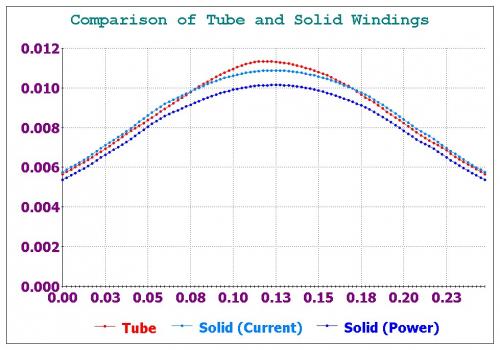
Even at zero frequency the difference between a Solid winding pattern and one shaped like a Tube is significant.
In the nine 20 AWG wire configuration with three sets of three per row the center wire is seriously dampened compared to the one's on the edges. By my estimate the center wire has an apparent resistance that is 40% higher than the others.
You can see the magnetic flux summary here:
.
.
There is a difference between "Equal Current" and "Equal Power" because the added resistance of the Solid wind requires a higher voltage (as in BackEMF) to drive the current through. (this gets exponentially worse at high frequency)
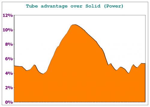
When you compare "Equal Power" you get this percentage difference in magnetic flux:
.
.
So winding patterns are very important.
I've read that for high frequency transformers they do not use more than one layer of windings because anything beyond that is a total waste.
.
This means that big thick coils are a terrible design.
.
When designing motors the closer to 1 mm (20 AWG diameter) your winding bundles are in thickness the better because that is the skin effect up to 1 kHz.
Any winding bundle of a thickness greater than about a single strand of 20 AWG wire is too thick and wasteful in both power and in weight.
This concept of a "Hollow Tube" gets very tricky when applied to motor windings because you have to wonder how you would introduce the hollow center while still being able to do multiple series windings in your pattern. Keep in mind that in the animation those wires go directly into the page so they are all parallel with each other, but just given a tube shaped pattern.
.
.
In FEMM you can set your Flux Density so that it displays colors that are relevant to what you are looking at.
Normally the Skin Effect and it's contribution to BackEMF is so far below the Flux Density of Silicon Steel you just don't see it. The BackEMF at zero frequency can only be seen if you are looking down in the 0.01 Tesla range.
So the animation cycles through the low spectrum of Flux Density in the range set as zero on one end and from 0.0005 Tesla to 0.01 Tesla on the other.
Normally the Flux passing through the Silicon Steel is near or above 1.0 Tesla.
What you begin to realize is that a coil is like a vortex where all Flux gets emptied outward. Everywhere else there is some Flux, but next to nothing inside the active parts of the coil.
The Skin Effect is that within that vortex any wire you put in there will experience an effect that is not to the benefit of that wire.
In short, you want tubes and not solid bundles of wires.
BackEMF cannot be eliminated because the vortex will always push things outward, but you can actually reduce it with a different mindset in the design.
.
.
You see a lot of guys playing around with Thin Flat Foil as an alternative to wire windings.
At low frequencies this seems pretty good because you always can get the edges to squeeze some current through even when the middle is acting as a BackEMF traffic jam.
But as the frequency increases (the animation goes from zero to 1 kHz) you can see that the Thin Flat Foil seems to want to fight against itself and if you look carefully there are little gaps between the Thin Flat Foil with reduced flux.
This state of complete chaos might actually produce some decent current flow, but judging by a few sample data points it's still running some very high BackEMF values.
In my opinion tubes are better than foil.
The tube shape more closly reflects what the current "wants" to follow, so as far as weight or efficiency is concerned it seems tubes are the ideal.
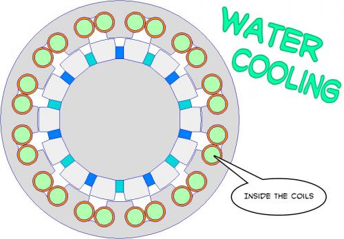
It's somewhat interesting to imagine combining water cooling with the design of the coil like I considered previously:
.
.
.
The more you learn about electricity and magnetism the more bizarre things seem to get.
Often there are tricks that can exploit things above what is obvious.
You would "think" that the ideal conductor would be a thin tube because of the Skin Effect, but actually there are ways to improve upon that.
It seems that having an opening somehow releases some flux from the interior of the tube shape and this improves performance.
At 1 MHz the square shaped area (which is exactly the same amount of copper as the tube) produces a real power that is 27% higher. (as measured in FEMM)
Compared to a solid bundle of copper wires and at high frequency the difference could be as high as 70%.
Truly bizarre.
.
.
.
The animation begins with a solid copper wire with a diameter of 1/4" which represents the ordinary coil cross section in many electric motors. (per winding slot)
The frequency is 1 kHz throughout the entire animation which is the maximum that most of our motors ever reach and the current is the same at a constant 500 amps which is very moderate for that cross section of wire. It's roughly equivalent to 50 turns of 20AWG wire in cross section, so just 10 amps current per wire.
At first the wire is solid, but then it becomes a tube of thinner and thinner thickness while retaining the exact same cross section area, so it's an apples to apples comparison.
As the tube gets bigger and thinner the Voltage Drop Declines and the reduction is represented by the percentage in the upper right hand corner.
What does this mean?
It means that BackEMF will be Reduced which means you could either spin the motor 25% faster or redesign the kV to be lower so that it has 25% more torque. (however, since the Skin Effect issue is more significant at higher frequencies you might just accept a higher top speed)
The question of whether BackEMF can be reduced has been answered:
.
"Yes, BackEMF can be reduced by exploiting knowledge of the Skin Effect on a conductor".
.
...what this doesn't answer is the increase in overall volume this requires and the practicality of squeezing this into a motor design, but "in principle" the basic physics is correct.
.
.
Well we know that you can reduce BackEMF if you fiddle around with the shape of your conductors, but there is a limit to how much that can achieve at low frequency. If we were dealing with frequencies in the 1 MHz range the primary issue would be reducing the skin effect because it goes nuts at those high frequencies. Most electric motors can get by at 1 kHz or less and things aren't really that bad there.
So what is BackEMF really?
The primary cause is the eddy currents caused by the skin effect inside the conductor itself.
The secondary effect is that you create an Inductor that acts like a spring that wants to spring back against your attempts at higher frequency.
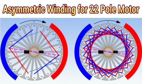
I've noticed some guys playing around with a different winding scheme where they create Assymetric Windings that seem to act as if they are two Inductors. These out of phase coils are configured so that their inductance is passed forward during rotation. They have actually built these motors.
This might violate some basic law of physics, but until I do some FEMM simulations I will not be able to say for sure.
This is different than 12N,14P RC motors that do a kind of electrical gear reduction in their windings. Those RC motors are still behaving as classic inductors.
So I'll fiddle with it and see if there's anything to the idea.
.
.
...the idea seems similiar to a Shaded Pole motor because one phase interacts with the next.
.
.
.
Okay, I think I'm beginning to comprehend the underlying theory upon which this Asymmetric Motor idea rests.
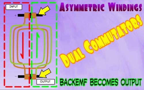
An Inductor will build up it's magnetic field because as currents travel through a conductor (copper wire) the skin effect creates eddy currents that spin in perpendicular directions creating their own magnetic field. This does nothing but store energy into something that is wasteful. This wasteful perpendicular energy goes by the name BackEMF and is Lenz Law. But an Inductor can also be seen as like a battery or capacitor because other than resistive losses the energy stored goes "somewhere" and could actually be captured.
The "Flyback Diode" is an example of how the controller deals with this rebounding of energy when the switch is disconnected on an Inductor.
.
.
So the Asymmetric Wound Motor with Dual Commutators allows the BackEMF to recirculate back into the motor again, but it's reintroduced on the opposite phase. In effect the Asymmetric Wound Motor attempts to take the place of the Flyback Diode. But apparently you could also just redirect that energy elsewhere too, so it behaves like a motor / generator in two halves.
The net effect should be a motor which behaves the same as a traditional winding but with significantly less BackEMF which means you require less voltage to achieve the same maximum rpm. This would permit lower kV motor winds and should improve efficiency while reducing current requirements. Lower kV means less current required, however, the concept of "kV" is itself built into the standard motors that lack a Flyback Diode / Asymmetric Winding philosophy so it would be interesting to see how the math might work out.
Certainly an interesting idea...
.
.
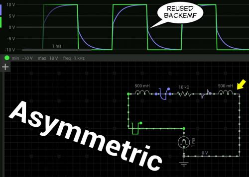
As a circuit a Symmetric motor can be seen as an Inductor and a Resistor.
.
.
With an Asymmetric motor you are splitting the Inductor in two and the effect is to retain that BackEMF energy and transfer it between the Inductors.
This gives the appearance of lower BackEMF because on each switch in polarity you are getting an extra boost as the two Inductors interact with each other.
From the circuit perspective this is really easy to understand.
Just looking at the circuit results it appears that a 10% improvement in coil "on" time would occur and this will mean less advance will be required at higher frequencies. This effect gets more extreme as the frequency increases.
.
The Asymmetric concept makes BackEMF work with the motor rather than against it.
.
.
So a connection of two separate ideas just "linked up" in my head.
The idea of the Asymmetric motor is to balance two Inductors so that as they function in parallel the BackEMF will cancel each other out. In effect it's recycling energy rather than fighting against it.
The other idea is the concept of "parallel paths" of magnetic flux that are "switched" between those two optional routes much like a transistor. With a magnet as the driving force for magnetic flux (rather than brute force originated by the copper coils) the energy to switch back and forth is very low.
In the animation I'm switching flux paths at a cost of a watt and that's a massive three inch wide hunk of one inch deep silicon steel.
.
What if a motor used BOTH parallel flux paths AND BackEMF recycling?
.
And why not throw in reduced Skin Effect coil configurations too?
.
.
.
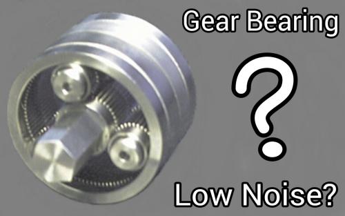
I want to revisit the John Vranish Gear Bearing idea.
Looking at the abandoned prototype that the E-RAM system attempted there are some things that stand out about their base configuration. First, it's not a "Gear Bearing" at all but an ordinary compound gear reduction using some ordinary bearings with a pin physically restraining it. This introduces some wiggle into the design. Then you add that the outer shell is quite large and thin so it's naturally going to resonate like a bell making noise louder.
.
.
...I'm still of the belief that a true John Vranish Gear Bearing has the potential for the performance that is desired.
http://www.techbriefs.com/component/content/article/ntb/tech-briefs/mechanics-and-machinery/5848
.
The teeth in the upper and lower halves are shifted angularly, relative to each other, by precisely a half-tooth interval. This gear bearing meshes with a copy of itself. The upper and lower teeth are beveled and partly interdigitated where they meet. The contact between the beveled surfaces of the upper and lower teeth provide a thrust-bearing capability in a manner similar to that of the contact between the crowns and rollers of the roller gear bearings. Moreover, a planetary assembly containing phaseshifted gears holds itself together in a manner similar to that of an assembly containing roller gear bearings as described above.
.
...so there are subtle "secrets" that others are likely unaware of. The compact nature of the Gear Bearing design coupled with a thick outer shell and "secrets" to tooth patterns could knock the noise down significantly.
I'm not willing to write the Gear Bearing off as a solution for high powered systems seeking high power-to-weight ratios.
.

.
.
https://en.wikipedia.org/wiki/Epicyclic_gearing
.
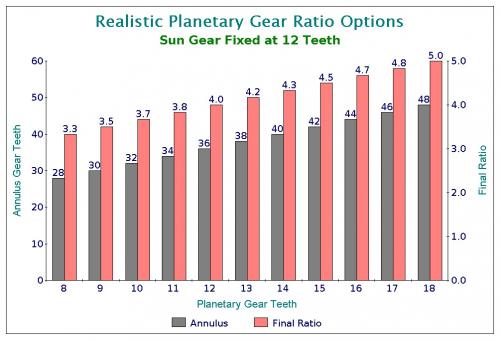
If the annulus is held stationary and the sun gear is used as the input, the planet carrier will be the output. The gear ratio in this case will be 1/(1 + Na/Ns). This is the lowest gear ratio attainable with an epicyclic gear train.
.
Ratio = 1 / (1 + 36/12) = 0.25 or 4-to-1
.
.
Assuming you start with a 12 tooth Sun gear in a planetary gear configuration your options are fairly limited as far as reduction. Standard reduction would be about 4-to-1 and the higher end is only 5-to-1.
This would be that 4-to-1 design:
.
.
Then you match that to a specifically designed Left Side Crank mounting which would include a freewheel to allow the cranks to operate without power.
.
.
Your output would be:
Sun 12 --> Planet 12 --> Annulus 36 : Ratio 4-to-1
Drive gear 12 --> Big Gear 120 : Ratio 10-to-1
Overall 4 * 10 = 40-to-1 Reduction
Motor Rpm 4000 ---> Output 100 Rpm
The funny thing is that I haven't seen this done yet in spite of how simple and light weight it would be. You would need a 20 DP 120 tooth front Left Side Crank gear to be made of aluminum most likely. Plastic might work if this is intended for 250 watt power input. Weight could be really low... like 3 lbs.
Many guys use sprockets and chains but you can't get 120 teeth in a 6" diameter even with the go kart chains (#219) so a solid gear would make this different. You can of course put holes in this 120 tooth gear to reduce weight like other front chainrings.
.
.
Using the same concept...
Your output would be:
Sun 12 --> Planet 12 --> Annulus 36 : Ratio 4-to-1
Drive gear 4 Cam Rollers --> Big Gear 40 : Ratio 10-to-1
Overall 4 * 10 = 40-to-1 Reduction
Motor Rpm 4000 ---> Output 100 Rpm
.
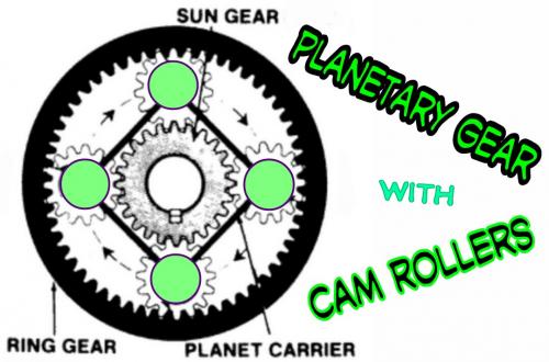
.
Cam Rollers
By using Cam Rollers you increase the teeth size by a factor of three and this reduces the precision necessary and permits the use of a plastic gear which reduces noise.
Cam Rollers that are used in automobiles are very durable, but if they did wear out you could design the system so they could be replaced.
The planetary gear spins it's Planets while the Sun and Annulus remain fixed. This means the Cam Rollers could be directly attached to this spinning region. One might even design a shaft that went through both the Cam Rollers and the spinning Planet gears.
Very low friction because of the Cam Rollers. (lubrication is internal)
Dirt tolerant.
.
.
Okay, so I've been struggling with this animation because it takes a lot of manual move operations to do this when you haven't done it using automation.
My first error took some time to figure out.
Look at the animation above:
"How many times does the inside circle rotate per revolution?"
Three?
No... it's three minus one equals two.
It's not exactly an intuitive thing to see.
So after I realized my math was wrong I finally got to knowing the correct way to rotate all the elements involved.
Left Side Crank Motor Location
The gear reduction is:
Planetary Gear (12-12-36) does a 4-to-1 reduction.
Cam Rollers (4-40) does a 10-to-1 reduction.
Overall you get 40-to-1 reduction:
.

.
The animation was a problem.
The formulas that locate the gears are correct, but the timing of the frames makes the planets appear not to move and the sun looks like it's moving backwards.
So I'm going to have to do this again (hours of effort) using different timing in order to get it to look right. You can't easily tell what it looks like in animation until you do it.
This was created using just seven frames repeated over and over.
.

.
40-to-1 gear reduction without cycloidal or compound gearing !!!
.
.
By reducing the number of teeth by two thirds I was able to get a reasonable animation that at least gives a taste of the 40-to-1 reduction going on.
I'm going to either need to learn the FEMM scripting language or use some other tool to do it any better. This was just nine frames, but it took a couple of hours to create. Ideally this would have many more frames to make the motion appear smoother.
Anyway... 40-to-1 reduction is possible without needing either the cycloidal reduction (which creates vibration) or the compound reduction (which creates friction) so this might be the most simplified solution.
Pretend it's really high quality like this:
.
.
...52 frames for one third of a revolution.
.
.
This is a different thought.
When you look at the planetary gear it has three separate input / output / fixed options.
http://www.torcbrain.de/uebersetzungsrechner-planetengetriebe/?lang=en
For 12-12-36 we get:
Ratio 4-to-1
Ratio 4-to-3
Ratio 1-to-3
...but an idea came to mind.
A motor could be designed so that there was a central spinning part that had magnets (Sun) and a second spinning part that had magnets. (Planets)
You could then find some fractional difference between the two so that you did something like the John Vranish Compound Gear idea where the output was defined by a slight difference in the two. (but now no friction problem)
For output you use a planetary gear that included it's own fixed Annulus.
I'll have to work on the idea more and get better animations, but it seems like high gear reduction could be built into the motor because of these Counter Rotating components.
.
.
Note how these magnets rotate opposite each other, but align as they pass, so it should be possible to introduce a coil into this to drive it from the area between them.
Something like a 6 magnet Sun and 8 magnet Planet would give:
4 - 3 = 1 ...so a 4-to-1 gear reduction, followed by the mechanical 4-to-1 gear reduction would produce 16-to-1 right off the motor.
16-to-1 can easily be dropped down after that.
You have to mentally superimpose the mechanical gears above this animation to imagine this.
I'm very near to what the Magnomatics guys have done, but I'm combining their thinking with an actual physical planetary gear making a kind of hybrid result.
Sort of a combination of:
Magnetic gearing
Planetary gearing
Compound gearing
...all wrapped into one concept.
.
.
https://en.wikipedia.org/wiki/Epicyclic_gearing
.
.
.
.
.
So rather than searching blindly for high gear reduction I use the formulas and scan through all the likely options.
The goal is to get the Annulus to rotate in the backwards direction just slightly slower than the forward direction of the Sun so that the Planets will generate output that reflects the fractional difference much like a John Vranish style compound gear reduction but without that messy friction problem.
Seems like 8 magnets with 3 coils should work with a 2 magnet Sun.
12 and 5 might be better. (would require 5 phase controller though)
Will have to try it in FEMM.
Gear reduction of 50-to-1 or more is possible with a counter rotating motor.
.
So the forward rotation can be defined as 1.
The reverse rotation can be defined as -0.5.
If you used a planetary gear of:
Sun : 17
Planets : 8
Annulus : 33
...then the ratio of Sun-to-Annulus is:
17 / 33 = 0.51515152
Note how close -0.5 is to 0.51515152.
Also note that odd tooth count Sun gears have higher maximum ratios than even.
When you plug this into the formula for planetary gear ratios you get:
100-to-1 reduction
Something like a Switched Reluctance motor can spin up to 10,000 rpm (very little BackEMF) which means you get an enormous amount of output torque because everything gets multiplied by 100. Output is only 100 rpm. And be reminded there is no friction issue like with a Compound Gear reduction because the gear teeth are interacting at the same speeds. Standard involute teeth profiles will be fine.
http://www.crdriver.com/#!techy-stuff/mthdf
History of the Counter Rotating Motor:
The first counter-rotating electric motor was first seen in an issued U.S. patent in the early 1900s. Over the decades several versions of counter-rotating electric motors have appeared, but many were clearly theoretical creations, some were functionally inoperable, and others mostly impractical for various obvious reasons. However, not one mention was ever made of the high efficiency/effectiveness of this type of rotational drive. Increased torque was mentioned for CR motors, but never a decrease in electrical power input relative to increased mechanical power output. Since nearly all of the versions were powered by a continuous supply of electricity, there was, apparently, no interest in conserving the amount of electricity used to power the device. The versions utilizing a battery were found in torpedoes that have an extremely short half-life, so battery life, presumably, was not a potential problem.
Last night I had one of those profound insights...
Why does Compound Planetary gear reduction suffer from high friction?
The answer is that when you drive through the Annulus gear your Planets teeth travel along a path that dives into the Annulus teeth which when under load means the teeth must scrape their way past each other before bottoming out.
The way to design a Planetary gear reducer for low friction is to drive through the Carrier because the load will only apply itself in agreement with an Involute Gear interaction:
Another way to say it is that for Planetary gearing:
"Avoid driving the Annulus in all cases."
This might mean that you choose NOT to get the counter rotation done using a Planetary gear, but having to design a counter rotating motor is probably unnecessary. So the first stage is likely a simple gear, then followed by the Planetary gear. This is important because if you just move the friction to the front end rather than the back end you haven't gained anything.
I took the generic formulas that define planetary gear ratios and solved for all six possible cases of having one part fixed and the other two in motion.
Then I added the second planetary gear where the output of one would be the input of the other while fixing the input-to-input of the original planetary gear so that there becomes just one final output.
You can see that insanely high gear reduction is possible.
But that's probably too much as all that is desired is between 30 and 70 to one final reduction.
What this does is free you up to design the planetary reduction system based on the goal of minimizing friction as your first priority, then as an afterthought dealing with the overall gear reduction which is actually rather easy to achieve.
My first discovery upon applying these formulas is that certain combinations have problems with planet spacing. If you want an equal number of planets on the two sets you need the ability to match them up as far as rotated angles.
The formula for that is 360 / (Sun + Annulus) = Spacing angle.
In this case it takes a multiplier of 16 and 15 to achieve matching 90 degree planet spacing.
Note that the friction (represented by the yellow arrows) will be low because the torque will apply at the center where the gears make contact.
Final output would be represented by the reddish arrow... and the rotation would be one turn of the Carrier for every 45 turns of the (dark red) Sun. The Sun is connected across both sets and have the same teeth and in this example spin together in the clockwise direction.
The outer rings (Annulus) are of different sizes but could be built separately and then bolted together. In fact this might be the way to package things up neatly. The outer rings rotate in the counter clockwise direction in this example.
All the teeth can be the SAME PITCH which makes buying this as generic gears rather easy.
So there you have it... 45-to-1 gear reduction with low friction.
Similiar in concept to the John Vranish design, but makes different parts fixed which should reduce friction.
I'm not a huge fan of needing two sets of planetary gears even if they have low friction simply because there are just too many teeth to maintain.
So the logic here is to use Halbach Arrays in a very exotic configuration.
The inner ring of magnets has 10 magnetic poles and a total of 20 magnets.
The outer ring of magnets has 14 magnetic poles and a total of 28 magnets.
The middle region has 12 zones of magnetic variation.
The net gear ratio when these counter rotate will be 100% rotation in one direction (assume the inside) to -10/14 in the other:
-10/14 = -5/7 = -71.4%
This can be matched with planetary gears on the order of:
Sun 52 --> Planets 12 --> Annulus 76 (-0.6842 or -68.4%)
Sun 40 --> Planets 9 --> Annulus 58 (-0.6897 or -69.0%)
Sun 36 --> Planets 8 --> Annulus 52 (-0.6923 or -69.2%)
Sun 32 --> Planets 7 --> Annulus 46 (-0.6957 or -69.6%)
...to create a gear reduction of 80-to-1 and above.
If this were done as an Ironless design you could run at high rpm without any hysteresis losses so a very, very lightweight motor could spin very fast creating large amounts of torque while being geared way down to 100 rpm output.
permanent magnets have a lot of weight . what if we used three sets of coils and a power full controller ??
thank GOD I wake up above ground !!!!
Density of Neodymium Magnets : 7.3–7.5 (g/cm3)
Density of Silicon Steel (iron) : 7.65 (g/cm3)
So magnets and iron weigh about the same, but if you use iron like this:
...you have to deal with hysteresis:
So it seems that a high rpm motor can run more efficiently if it's mostly magnets and little to no Silicon Steel. (iron)
In the animation every time you charge up the Silicon Steel it takes energy that you never get back and to make matters worse you have to erase the memory of it being charged up.
http://www.russodaily.com/reports/Nine_Solar_Racers_Have_The_CSIRO_Advantage_999.html
It's not that there's no competition for our motor," said Dr Howard Lovatt, part of CSIRO's original design team at CSIRO Materials Science and Engineering. "People have been trying to design a better one, but it's been ten years and they just haven't been able to do it."
CSIRO's motor is the most efficient in solar racing at 98 per cent efficiency (converting 98 per cent of its fuel - electricity generated from sunlight - into useful power). It's also extremely light: the whole wheel - tyre, motor and all - weighs 14.5 kilograms. Other in-wheel motors used in solar racing typically have energy efficiencies of less than 95 per cent and weigh twice as much, not including the wheel and tyre.
The CSIRO design which uses no Silicon Steel and all Neodymium Magnets can potentially be 98% efficient. But the solar racers have no weight worries like on an ebike where we want to be down below three or four pounds. (14.5 kg is 36 lbs)
Friction caused by gear reduction reduces efficiency by at least 3% and that's why I wanted to reduce the planetary gears to a single set to reduce friction. (98% minus 3% equals 90%-95%)
Present day mid drive motors are probably running around 70%-80% efficiency by the time you reach the rear wheel but the expanded gearing options of multispeed gearing means that overall efficiency can be sometimes better than a hub motor. (90% efficiency in optimal conditions, far less uphill... like 65%)
There is an interesting ongoing discussion taking place on endless-sphere:
https://endless-sphere.com/forums/viewtopic.php?f=30&t=47930&start=575
If you want to match the power to weight of a small RC motor, you simply need to use the iron and copper at the same rates and current densities, but configured in a geometry that provides the desired output drive torque as a function of a single stage.
Later there is this response:
You are cruising along at 45 kph on the flat. You come to a 15% gradient. What is the ratio of the difference in torque requirement, assuming you don't want to slow down?
So the simple (comical) solution would be:
"When you arrive at a hill you swap out your present motor with another that has higher torque."
In the animations below the percentage is relative gear ratio for a multispeed transmission with a range of 500%. All other parameters are of a typical mountain bike.
Eventually we get to this quote:
More acceleration than your tires can handle all the way past a speed you want to be going is where putting the drivetrains mass into copper and iron rather than parasitic things can take you, and it's a nice place to be.
So you see all you need to do is get 250 watts to burn rubber !!!
https://endless-sphere.com/forums/viewtopic.php?f=30&t=78923
In the chart above I examined what happens as you increase the Radius of the motor while at the same time making the larger motor Hollow on the inside.
Obviously it can't truly be Hollow because the motor will need some support, but just like a bicycle wheel with spokes the inner region of a motor can be mostly air.
You then adjust the width to create a constant overall weight based on volume.
The answer.
Yes. A larger Radius motor that is Hollow will achieve more Torque for the same weight.
Does this cancel the effect of gear reduction?
Probably not.
The increase in Torque is about the same as a 2-to-1 reduction in gear ratio, but still the increased Radius is a plus and worth knowing about.
Hub motors are entirely dependent on this insight.
For me this essentially ends the debate.
When you consider a constant Power it is made up of a combination of Torque times the Speed of rotation of the motor. So Gear Reduction acts as a direct linear "Torque Muliplier" with no reservations other than that if motor rpm becomes too high you get excessive Iron losses due to Hysteresis.
And I included the reduced weight for a Hollow larger Radius on lower reduction based on the Radius required in order to achieve the needed Torque.
So what seems to be true is that the Hollow design makes perfect sense when you are building a direct drive motor. But once you get into Gear Reduction the "Torque Multiplier" effect pretty much erases any difference in Hollow vs Solid motor design.
At 50-to-1 Gear Reduction (and assuming an output of around 100 rpm which seems a good ballpark figure for hub motors or mid-drives) you are at the point where the Hysteresis problems occur, so I stopped there.
An ebike with a 50-to-1 reduction means:
Maximum Motor RPM : 5000
Output RPM : 100
The answer:
"Small motors running fast are lighter weight for the same power."
And Multispeed Gearing simply adds more Torque options, so it still seems to me that the mid-drive is the correct choice and this is even more true when you deal with legal power levels like 250 watts or 750 watts.
Power = Torque * Speed
Let's continue on this theme:
Power = Torque * Speed
In order to fully maximize weight dedicated to the motor we want the "useful elements" (magnets, iron, coils) to be spinning as fast as we can up to and below the point where high rpm problems appear. Realistically that means electrical rpm that equates to about 5000 rpm for a small motor.
But gear reduction of 50-to-1 can cause friction. So in order to reduce friction we must design a motor in such a way as to get to 100 rpm output with the fewest reduction stages.
The Counter Rotating Motor with Single Stage Planetary Reduction delivers everything you want.
High speed
High gear reduction
Single Stage reduction
This lower animation shows how it might be done as an Axial Flux design rather than a Radial design. Think of it as slicing through the motor in layers. The animation goes forward and reverse through the motor.
With 4 magnets vs 6 magnets you get a Counter Rotation of:
4 / 6 = 67%
...from there you pick a Planetary Gear that gets close to the same but is just fractionally different. It's the slight difference that permits high gear reduction. (this is true for all compound gear reduction systems)
The brute force method of belts, sprockets and chains are all eliminated.
I've looked at the concept of Harmonic Drives before but hadn't really investigated their internals much until now.
Efficiency is pretty good around 50-to-1 for this product (~92%):
http://www.hanzh.com/product-4.html
The concept is similiar to cycloidal designs which advance a single tooth (or two teeth) per revolution of input.
The "band" is flexible so it's made of the kind of hard steel they use for springs and supposedly the eccentric bearings tend to wear out before the "band" does.
The biggest advantage is that these can simply be bought and installed, so it's very easy to achieve 50-to-1 reduction without any real effort.
This is very interesting.
Dr. Ernie Davison has combined the concepts of a Switched Reluctance motor with a Harmonic Drive.
But with a twist...
There is NO ROTOR !!!
I'm going to have to create a FEMM simulation of this idea, but basically he uses magnetic flux to simply "bend" the Harmonic flexispline.
You end up with exceptionally high gear reduction and extreme torque.
The only moving part is the flexing of the Harmonic flexispline.
Looking back at the discussion on endless-sphere:
https://endless-sphere.com/forums/viewtopic.php?f=30&t=78923&start=25#p1166611
The size is rather extreme in that this motor is nearly 16" across.
Weight is 4.5 lbs which is an acceptable maximum.
Output is 1000 watts at 400 rpm and 94% efficiency.
...so other than the diameter being excessive this compares well to the Harmonic Drive as far as power-to-weight ratio. (I would guess)
It would be interesting if they were to limit diameter to something equal to a typical bicycle chainring.
A more realistic diameter would be 8" or about 200 mm.
What is very attractive about the Harmonic Drive is that it's very compact yet generates massive torque at very low rpm. Plus, the Harmonic Drive has no fast spinning parts (just a flexispline at low rpm) so the only losses are whatever it takes to create the flex in the flexispline itself.
It's interesting to examine the extremes of design.
Pages