Andy, Thanks and thats great news. I just googled goodrum/fechter bms and found your posts on endless sphere...wow! You've been busy! Nice work! So I thought my pack was staying pretty well balanced, now I know better. Well thank you so much for all that info. Keep up the great work. Love the geek art reference.
Bill
2008 XM3500li Mods/Kelly KBL12251/84v 28cell 40AH pack/ Variable regen brake trigger on left brake handle/Givi/Cycle Analyst/Homemade BMS
KMX Typhoon Home build (recumbent pedelec) with two Astro Brushless 3220motors/twin castle Phoenix ICEHV 160/ Cycl
Yeah Andy, I think I'll want to make a rig like your's eventually. You thought of everything! With my cards it's like I'm working with stone tools. With you're system you can't miss if somethings wrong. That pak-traker with something to record the data is the way to go. If you develope a bad cell you can't miss it. Now I've got alot more work to do. But I love this kind of stuff. Much better than a stupid crossword puzzle eh?
Bill
2008 XM3500li Mods/Kelly KBL12251/84v 28cell 40AH pack/ Variable regen brake trigger on left brake handle/Givi/Cycle Analyst/Homemade BMS
KMX Typhoon Home build (recumbent pedelec) with two Astro Brushless 3220motors/twin castle Phoenix ICEHV 160/ Cycl
In a few more days we should have some GPS-checked speed testing done.
So far, the speedometer (GPS-checked) seems to be basically accurate,
but Andy has not gotten up to max speed yet. Here, we have had rain.
Also, around here, it is difficult to find a stretch of level road
where one can go 60 mph. Andy is going to "mount" a GPS soon,
to be able to get better data with both hands on the "wheel".
Cheers, Gary
XM-5000Li, wired for cell voltage measuring and logging.
Initial tests by AndyH show the 5000Li speedometer reading about 8% high (reads 55 at GPS 51). I think the 8% seemed uniform across the range.
Somebody said, as I seem to remember (perhaps in the ApteraForum.com), that in Europe the motorcycle speedometers MUST read 10% high. Is that true?
Hi Gary,
I dropped the tire pressure to the 33PSI recommended by the tire sidewall before last night's ride. Next time out I'll increase to 40PSI - it made quite a difference in speed and ride quality. Fortunately (for the drought) but unfortunately (for high-speed riding), we're getting rain and heavy fog in San Antonio.
The GPS is still hand-held, and there's room for at least a 1-2mph error as I stay on the road, read the speedo and GPS, and wipe the rain away from my face. :)
Speedo/GPS
10/9
20/19
30/27
40/37
50/46
55/51
My first runs at lower speeds showd the speedo to be spot-on up to 30mph - 20=20, 25=25. The tire pressure makes a difference.
I've owned German cars since the late 90s. German law requires speedometers to read at least 3mph fast. I can't speak for the rest of Europe. I lived in England for 4 years and Germany for 3, but didn't run many GPS speed checks in the 1980s... ;) My current car is a VW Passat wagon. Before I calibrated the speedo and fuel gage, the speedo read 4mph high at 70 and 3mph high at 50. Europe is still the primary market for scooters so I expect to see some 'over reporting' on all the speedos made for the Euro market - including the Vectrix.
The GPS is still hand-held, and there's room for at least a 1-2mph error as I stay on the road, read the speedo and GPS, and wipe the rain away from my face. :)
You can probably stick it onto the scooter temporarily with hot melt glue. I mounted a camera to the top edge of my Vectux windshield for about 10 months, when I finally pulled it off again it left no trace other than that the spot is a little more shiny than the rest of the screen, like NEW!
You just need to shape the hot melt glue into a bracket that holds on due to it's "embracing shape"; the adhesive force by itself (on a flat surface) is poor. That's why you can get it back off later on.
Stick-on velcro dots also worked well for relatively light things on relatively horizontal surfaces. On vertical surfaces heavy stuff gets knocked off the velcro when you hit bumps in the road.
This information may be used entirely at your own risk.
Hey Guys-- long time no write, I hope all is well with you. I use a lot of hot glue for the repairs I do on very expensive glass sculptures in my business. The hot glue comes off really slick with acetone, the acetone may affect a plastic surface(try a small area ahead of time that is out of the way) but it will not affect a metal surface. Here is the latest update on my XM6000(24cell): it will be out of the shop this week or next. I am really looking forward to giving you guys some info when it gets out. Until then keep up the good work....Mikie
Well I received my bms circuit board from TPpacks.com with no illustrated instructions like they advertized. Still waiting for the electronics from mouser.com, I didn't really know what a project I was taking on. I don't think I want to solder all this crap together. Any ideas what kind of place will do this and what it will cost? FYI the board is $49 and the electronics is about $90.
Bill
Still trying to rise above
PS Good to hear from you mikie, as far as I know you me and John are the only people I 've seen running 24cells. I look forward to you're input. 1164km and going strong!
2008 XM3500li Mods/Kelly KBL12251/84v 28cell 40AH pack/ Variable regen brake trigger on left brake handle/Givi/Cycle Analyst/Homemade BMS
KMX Typhoon Home build (recumbent pedelec) with two Astro Brushless 3220motors/twin castle Phoenix ICEHV 160/ Cycl
Well I received my bms circuit board from TPpacks.com with no illustrated instructions like they advertized. Still waiting for the electronics from mouser.com, I didn't really know what a project I was taking on. I don't think I want to solder all this crap together. Any ideas what kind of place will do this and what it will cost? FYI the board is $49 and the electronics is about $90.
Bill
Still trying to rise above
PS Good to hear from you mikie, as far as I know you me and John are the only people I 've seen running 24cells. I look forward to you're input. 1164km and going strong!
The build goes fairly easily, but there is a LOT of repetitive lead bending for the resistors and diodes. Follow the build order (short to tall) - it's difficult to get the 8-pin ICs under the taller components.
Don't expect to do it in one sitting. I've built three so far (a V1.5, a 12 channel V2.2, and a 21 channel V2.2) and it took three or four sessions to build the 21-channel board. Then more for wiring, connectors, etc.
Andy
edit... It looks like the instructions have been updated to include the most current schematic. I don't know yet about the KSA931 orientation.
A note from my last post - I said Europe is the primary market for scooters... Should have said primary non-Asian market...
I'm reading thru a summary of Toyota RAV4 EV driver experiences and see that the RAV4 speedometer displays 2-4% high. This suggests that for a 60mph speedo display, the SUV will be traveling 1.2 to 2.4mph slower - between 57.6 and 58.8 mph.
Andy, Thanks for the links, I figured they probably had it on the website somewhere. Well I'm not sure if I'm up to the task. The last time I did this much soldering I was 13 and was building a crystal radio set...and it never did work!
Bill
I love the smell of solder in the morning...It smells like victory!
2008 XM3500li Mods/Kelly KBL12251/84v 28cell 40AH pack/ Variable regen brake trigger on left brake handle/Givi/Cycle Analyst/Homemade BMS
KMX Typhoon Home build (recumbent pedelec) with two Astro Brushless 3220motors/twin castle Phoenix ICEHV 160/ Cycl
Using an inexpensive lead-bending jig (red, plastic, triangular, with slots for many desired lead-spacings) can make installing components a lot easier. Bend, "stuff" (insert) the component, repeat all 21 (or 42) times, cover the board with a towel to keep the parts from falling out, flip the board, pull up gently and spread each pair of "legs" slightly (to keep the component from falling out). Then, solder all 42 (or 84) legs and clip off the leads.
The "legs" (usually 8 or 16 in this BMS project) of ICs are manufactured "too wide" to go easily in the PCB holes. Without an "IC-insertion" tool (which temporarily bends all the legs so that they will go into the holes), you can (carefully) "roll" each side of the IC against a rigid, flat surface (table top) to re-form each row of legs just enough to go through the PCB board holes.
Make sure (double-check) that each component is inserted with the correct orientation ... BEFORE you solder!
The BIG part of the job is getting the wiring on the batteries. Make the wiring harness first, complete with the "ring terminals" that will go on the battery posts. For the 5000Li, start with one black wire (a little longer than needed) from pin "1" of a 22-pin (or 24, or more) connector (consider using the 24-pin Val-U-Lok series, or equivalent, available from Mouser) that will go to "Pack Negative". Use the "male-looking" connector which actually takes the "female" pins, to mate with the series' PCB recepticle connector ("female-looking", with male pins). No, do NOT connect any wires to the battery yet. Add wires for each cell's "positive" (red) terminal, each a little longer than needed. I suggest using a different color wire for the connection intended to go to the most-positive terminal of each 3-pack of cells.
Also, it would be good to label the wires and the intended connection points with the numbers 1 (Pack minus) through 22 (Pack Positive). Those with "enhanced" 24-cell Packs will need 25 wires, so you could use the 24-pin connector for the lowest 23 cells and add the 24th cell with another small connector from the same series.
Next, CAREFULLY remove the Pack-Negative and then the Pack-Positive connections from the Battery Pack (accessed from under the seat), putting the protective covers back on the cell terminals. For safety, never have more than one protective cover off at any given time.
Then, "strip" the scooter enough to access all the cells. On the 5000Li this requires removing everything "exterior" from the windscreen-and-instruments section to the wrap-around tail-light section. The seat can stay on, if desired. Pay close attention to what you are doing, because the re-assembly is even more difficult!
Long pause ... to complete the disassembly. Eat, rest, and wonder when X-Treme will offer factory-installed battery wiring. It would be easy for them to do, and not cost very much. Suggestion, do NOT do the electrical connections if you are tired, sleepy, frustrated, angry, or "under the influence".
Locate the connector where you want it, and protect the pins by plugging on a blank "female" (with no male pins) connector. Leave some extra slack. Route the LABELED wires (usually 3) to each 3-pack, gently cable-tie the wires together into a "group", combine with other groups going to the same location, and cable-tie this new "wiring harness" in place. Then, cut each wire to length, leaving at least a few inches of extra slack, and properly install the "ring-terminal" on the end of each wire. Carefully inspect each connection, because it will cost you many (maybe 4 to 6) frustrating hours to access it to "fix" it later.
Re-check your connections and start connecting to the correct cell terminal posts, just one at a time.
When finished, use a voltmeter to check that the voltages at the 24-pin connector. Put the negative meter probe through the "blank" (protective) connector to gently contact the female pin in your newly-wired connector. Select the appropriate DC Voltage meter range (or auto-ranging). Check that the voltage increases by about 3 or 3.5 volts on each higher-numbered wire. Then, double-check, since it is VERY important to get this right.
Long pause to re-assemble.
More later, with pictures.
Cheers, Gary
XM-5000Li, wired for cell voltage measuring and logging.
Re: My XM-5000li Experience (and the Upgraded XM-3500li)
Iccarus wrote:
Well I received my bms circuit board from TPpacks.com with no illustrated instructions like they advertized. Still waiting for the electronics from mouser.com, I didn't really know what a project I was taking on. I don't think I want to solder all this crap together. Any ideas what kind of place will do this and what it will cost? FYI the board is $49 and the electronics is about $90.
Bill
Still trying to rise above
PS Good to hear from you mikie, as far as I know you me and John are the only people I 've seen running 24cells. I look forward to you're input. 1164km and going strong!
I also did the 24 cell upgrade, I purchased an additional four batteries from Elite Power Solutions along with the TSL72-15 (24 cell) charger. The top speed was around 54 MPH (GPS), The maximum distance was still around 28 miles. The odometer reading is 2608.5 km (1321 miles adjusting for the inaccuracy) I just received the XM5000Li. I will post pictures comparing the two as soon as I can figure out the reason the images will not upload, along with some comments/observations.
Gary,Thanks much for the tips. I wired my cells already so at least that nightmare is over. It sounds like it's even more of a chore on the 5000. I think those little tips on the BMS construction will really help me. One tip to others is if you use a U instead of a ring terminal, or cut the top off the ring you don't have to remove the battery terminals completly you can just loosen them and slide the connector under. Just make sure it's in all the way and tighten the bolt firmly. Check all connections by pulling firmly on them first.
Henry, welcome to the club. The added power is nice isn't it. You're getting a higher top speed than me, were you on flat roads with little wind? I'm still not sure all my cells are getting charged fully(balance issues) but that should just give me better range, not speed. I get about 40 miles at 30mph. Did you balance your new cells with the stock batts?
2008 XM3500li Mods/Kelly KBL12251/84v 28cell 40AH pack/ Variable regen brake trigger on left brake handle/Givi/Cycle Analyst/Homemade BMS
KMX Typhoon Home build (recumbent pedelec) with two Astro Brushless 3220motors/twin castle Phoenix ICEHV 160/ Cycl
Hey Guys-- signs of the times, is it really happening? finally? Check out the website at Elite power systems below, they use to have many options for auto EV's now NONE are available! All prices on the batteries have been raised about 20% so it looks like they have been discovered and this Green Transportation Revolution is really starting to roll. Expect big breakthroughs in BMS tech within the year! See Ya....Mikie
Re: My XM-5000li Experience (and the Upgraded XM-3500li)
What is the diagnosis feature? Loud pipes saves lives... on an electric scooter,thats a good one! It would be nice to get an idea of range at 30 to 45 mph driving if anyone gets a chance on the 5000li.
Bill
2008 XM3500li Mods/Kelly KBL12251/84v 28cell 40AH pack/ Variable regen brake trigger on left brake handle/Givi/Cycle Analyst/Homemade BMS
KMX Typhoon Home build (recumbent pedelec) with two Astro Brushless 3220motors/twin castle Phoenix ICEHV 160/ Cycl
Re: My XM-5000li Experience (and the Upgraded XM-3500li)
The manual only explains 1 and 2. (3 - 5 are not explained.)
1. Faulty brake switch, kick stand down or missing, or motor overheating.
2. Controller overheat protection.
Thanks for getting the "Loud pipes save lives" I had it on the XM-3500Li and transferred it to the XM-5000Li. I hope people continue to understand the humor.
I plan on doing a series of evaluations (e.g. speedometer and odometer accuracy. Maximum speed of "Economy" and normal mode. The range evaluation will probably be only for 45 - 60 MPH, unless otherwise requested.
Re: Battery Monitoring - Fuse, Interconnect, and LVM
I am in the process of laying out a PCB that will provide these main monitoring-related functions:
1. For safety, fuse each line from the cells,
2. Provide connectors to allow convenient attachment of other monitoring devices (like the PakTrakr),
3. Provide a 2.1 volt cell-too-low warning,
4. Provide a 2.7 volt low-cell warning,
5. Provide a set of simple 5.0 mm jacks to connect a voltmeter (to measure any one cell's voltage).
I hope to have a completed board in about a month.
I am still trying to get X-Treme to allow these monitoring functions without voiding the warranty. This cell-wiring and the monitoring do not change the operation of the controller or the charger in any way. So, they might possibly permit this monitoring addition.
I decided to use the 24-pin Val-U-Lok connector, with Pack-Negative at pin 1. I decided that one row of 12 pins would hold the odd-numbered wires, and the other row the even-numbered wires. Thus, wire 2 (the negative terminal of cell 2) is next to wire 1 (Pack Negative), but in the adjacent row. This way, the negative of cell "N" is on wire N, and the positive of cell N is on wire "N+1". Wires 1, 3, 5, 7, etc. connect to the "pin-1" row, and wires 2, 4, 6, etc. connect to the other row.
1 3 5 7 9 ...
2 4 6 8 10 ...
looking down at the header-recepticle connector on the PC board.
I hope to be allowed to connect the two "low-voltage" warning lines to two of the unused LEDs in the Diagnostics indicatior in the instrument cluster. That would allow the driver to reduce speed (thus reduce the load on the battery Pack) and avoid over-discharging an unbalanced cell.
I believe that some form of monitoring of the cells must be done if one wants to attempt to get good life out of the battery Pack. And, when ThunderSky comes out with an approved BMS, we will be ready to connect to it without having to take the scooter apart to add wiring to each cell.
Cheers, Gary
XM-5000Li, wired for cell voltage measuring and logging.
Iccarus wrote:
Henry, welcome to the club. The added power is nice isn't it. You're getting a higher top speed than me, were you on flat roads with little wind? I'm still not sure all my cells are getting charged fully(balance issues) but that should just give me better range, not speed. I get about 40 miles at 30mph. Did you balance your new cells with the stock batts?
Thanks, glad I could join.
The added power is nice (and puts the XM-3500Li close to what I was expectating when I ordered it.)
I charged all 24 cells (the extra 4 cells are from Elite Power Solutions) right before the ride using the TSL72-15 (87.0V/15A DC) battery charger (The voltage reading is 88.4) and the BMS from eped (A very big THANKS! to eped.)
On a different note: I had problems with two battery packs (sets of four, total of eight) using the stock 20 batteries. I originally had one cell go bad, by the time I could ship it back to X-Treme another three cells had gone bad. X-Treme replaced the batteries. The replacement batteries never fully charged (even when the charge cut off because of the completed charge, it went into the "off-on-off-on-off" mode) so the replacement batteries dropped below 2.5v (The cutoff did not engage). X-Treme replaced this set of batteries also. I commend X-Treme for warranting the batteries without a hassle. Once I received the third set, I decided to use eped's BMS and along with adding the additional 4 cells. I figured what I was doing wasn't working, so I would try something new. The problems charging the batteries were gone! Once again, A very big THANKS! to eped. All I needed to do was attach the BMS when I attached the charger and disconnect the BMS when I disconnected the charger.
Sorry I was so wordy, now to answer your question. The road is flat with no wind. The temperature was around 35 - 40 degrees. I weigh around 175 lbs (depending on how much I ate last :)) The speed (54 mph) is after riding for 3 miles. (I going down hill for the first 1.5 miles, so the charge is basically the same as when I started. I travel a total of 10 miles to work. The XM-3500Li is off for about 9 hours. On the return trip (on the same level road. I've traveled 17 miles at this point) the speed is 51 mph.
Another different note: I noticed something I was not expecting with the XM-3500Li. With 20 batteries the amperage is Max 78.4, Min -0.5 and with 24 batteries the amperage is Max 80.0, Min -0.7 (using an Ideal 61-768 meter) I was expecting the 80 amps. What I was not expecting was the negative 0.7 amps. Maybe there is a little bit (may be insignificant) of extra power. It would be enough to partially power the lights (not enough to charge the batteries).
Henry, No words are good. Can't learn without them. Yeah I almost put my new 4 cells in with the stock batts at a full charge. Then I realized that both sets had to be at the same state of charge.(SOC)Be careful though about running the pack to low. The low voltage cutoff on our controllers is 52.5v. 20cells into 52.5v=2.62v per cell which is fine it's above the 2.5v recomended LVC. 24cells into 52.5=1.87v per cell, thats below the recomended LVC so this will stress the pack. I'm using balance/monitor cards so I don't have to worry about it. My cards blink off at 3v so I just back off the throttle till I cant go any more without the cards going off. Anyway what I'm trying to say is, try not to run the scooter till the controller cuts off. When the scooter starts slowing down very noticably don't push it just find a place to charge. You may know this already but I just want to make sure.
Bill
2008 XM3500li Mods/Kelly KBL12251/84v 28cell 40AH pack/ Variable regen brake trigger on left brake handle/Givi/Cycle Analyst/Homemade BMS
KMX Typhoon Home build (recumbent pedelec) with two Astro Brushless 3220motors/twin castle Phoenix ICEHV 160/ Cycl
Thanks for the reminder on the LVC, I had forgotten it was at 52.5v.
I used the post from a while back where someone posted how to attach a 12 volt (Optima, I think) to the XM-3500Li without affecting the normal circuitry so the LVC still works as it should. I used four "TS-LFP40AHA" instead. I did find that at the end of 20 miles (normal daily round trip commute) the additional batteries voltages were slightly higher than the standard 20 batteries. This out of balance condition was managed really well by the BMS eped created. The voltage on each battery was 3.68 at the end of the charge. I find my realistic range (50+ mph) is about 25 miles (each battery is about 3 volts). The volt gauge goes below 1/2 after 28 miles (mph drops to around 43 mph) and gets really close to engaging the LVC at 30 miles.
yeah, the optima battery is a good cheap alternative. You can fit two of them under the seat. WE tried this for awhile. We hooked them up in series for running then took them out of series for charging(takes 2 minutes maybe)but the optima is 38AH which is a problem when the pack is getting low. We have run the 3500li with a pack at 105v full charge without a problem. However I WOULD NOT RECOMEND THIS... after doing the solder wicking mod (in another post) on the controller my friend fried his controller doing a fast start from a stop. However I wicked two of the shunts on my controller and got much better pickup but it doesn't seem to effect the top speed much.(and nothing has blown so far) I love mine despite it's minor flaws.
Bill
2008 XM3500li Mods/Kelly KBL12251/84v 28cell 40AH pack/ Variable regen brake trigger on left brake handle/Givi/Cycle Analyst/Homemade BMS
KMX Typhoon Home build (recumbent pedelec) with two Astro Brushless 3220motors/twin castle Phoenix ICEHV 160/ Cycl
Well, I found a minor "design problem" with the 5000Li:
The implementation of the mounting bracket for the License Plate.
1. In trying to mount the California license plate, if one tries
to center the plate, the mounting holes did not match.
So, just drill new holes, right?
Slightly difficult, since the two new holes need to be right on
two of the four slight bends in the bracket.
Why are these bends there at all?
Presumably so that the mounted license plate will clear the heads
of the bolts that attach the bracket to the rear fender.
But ... the slight existing depression made by the bends is insufficient
for the plate to clear the bolt heads. The depression needs to be at least
twice as deep, or, for good measure, make it three times as deep.
And, put the bends further inboard so the mounting holes can be used.
So, I re-bent the bracket, although somewhat crudely, since I do not have
the proper tools to do the job, and my wife was unlikley to let me buy
a sheet metal "brake" just for this job. (grin)
Now, the mounting holes in the bracket can be used to mount the plate.
Cheers, Gary
Cheers, Gary
XM-5000Li, wired for cell voltage measuring and logging.
A 3.7 v average is not good. One cell at 2.7 and another at 4.7 would be a 3.7 average.
What you want (of course you know) is all cells at the same near-full State of Charge (SOC, or "fullness"), all near "full".
If one starts with the cells nearly balanced, the 5000Li TS smadt pulse-charger MIGHT keep the cells balanced, we are not sure.
Starting with the cells not balanced, as delivered, it APPEARS that the TS charger would be likely to overcharge the higher cells. We have not wanted to sacrifice our own batteries to do the test.
Without a BMS type function to protect each cell from overcharging, it seems unlikely that any two-wire "Pack-Charger" can avoid over-charging a high cell.
Using a voltage-activated shunt to bypass charging current (or other protection) seems to be a necessity. A simple half-amp shunt used with the TS charger seems to do a good job as long as the imbalance is not too large. With a large imbalance, the initial 14-amp charging could still over-charge a high cell.
Manual charging of single low cells will help (but would void the battery warranty), so manually discharging high cells before doing any "pack" charging might be necessary.
However, adding the required 22 wires to the 21 cells, just to be able to CHECK the cell voltages is a SIGNIFICANT job, and might possibly (hopefully not) void the warranty. Monitoring and checking the voltages does not change the way the cells are charged with the TS charger.
Cheers, Gary
XM-5000Li, wired for cell voltage measuring and logging.
The opinions expressed by certain members of this site are not specific in knowledge nor transferable nor meaningful in any way shape or form:
Re: Warranty, are you really serious that Xtreme is going to know what you have or have not done to your bike? Are you going to ask them permission before you do anything? Do you really think that if your controller dies because of a fault of there own that they will come to your house and fix it for you? Do they have little birds like Santa Claus does looking in the window of your garage and taking names down as to who is a naughty forward thinker EV'er and who are sheep? This is the company that advertised a BMS system and Regen Brakes and did not deliver them nor offer a discount nor apologize to every XM3500 owner out there. To make up for the BMS snafu they have put a warranty of 2 years on your batteries. I would assume that once we keep flooding them with burned out batteries they either will replace as they promised or will ignore us, or develop a workable BMS system and Sell It To We/Us who were promised it in the first place. WE on these pages are the ones doing all this research and development, WE ARE YANKEE INGENUITY AND THAT IS WHAT IS HAPPENING ON THIS SITE. We are taking the ball (finally) into our own hands one step at a time and making this burgeoning technology happen. The Chinese and Alpha are there to make money at their risk and we are readily happy to comply. However WE want more speed/distance/reliability/communication and any warranty will not stop me/us from getting all of those improvements for ourselves and SHARING WHAT WE LEARN WITH OUR FELLOW EV'ERS registered on this site.
End of tirade and rant....as always (keep up the forward thinking and risk taking) Best Mikie


Andy, Thanks and thats great news. I just googled goodrum/fechter bms and found your posts on endless sphere...wow! You've been busy! Nice work! So I thought my pack was staying pretty well balanced, now I know better. Well thank you so much for all that info. Keep up the great work. Love the geek art reference.
Bill
2008 XM3500li Mods/Kelly KBL12251/84v 28cell 40AH pack/ Variable regen brake trigger on left brake handle/Givi/Cycle Analyst/Homemade BMS
KMX Typhoon Home build (recumbent pedelec) with two Astro Brushless 3220motors/twin castle Phoenix ICEHV 160/ Cycl
Yeah Andy, I think I'll want to make a rig like your's eventually. You thought of everything! With my cards it's like I'm working with stone tools. With you're system you can't miss if somethings wrong. That pak-traker with something to record the data is the way to go. If you develope a bad cell you can't miss it. Now I've got alot more work to do. But I love this kind of stuff. Much better than a stupid crossword puzzle eh?
Bill
2008 XM3500li Mods/Kelly KBL12251/84v 28cell 40AH pack/ Variable regen brake trigger on left brake handle/Givi/Cycle Analyst/Homemade BMS
KMX Typhoon Home build (recumbent pedelec) with two Astro Brushless 3220motors/twin castle Phoenix ICEHV 160/ Cycl
In a few more days we should have some GPS-checked speed testing done.
So far, the speedometer (GPS-checked) seems to be basically accurate,
but Andy has not gotten up to max speed yet. Here, we have had rain.
Also, around here, it is difficult to find a stretch of level road
where one can go 60 mph. Andy is going to "mount" a GPS soon,
to be able to get better data with both hands on the "wheel".
Cheers, Gary
XM-5000Li, wired for cell voltage measuring and logging.
Initial tests by AndyH show the 5000Li speedometer reading about 8% high (reads 55 at GPS 51). I think the 8% seemed uniform across the range.
Somebody said, as I seem to remember (perhaps in the ApteraForum.com), that in Europe the motorcycle speedometers MUST read 10% high. Is that true?
Cheers, Gary
XM-5000Li, wired for cell voltage measuring and logging.
Hi Gary,
I dropped the tire pressure to the 33PSI recommended by the tire sidewall before last night's ride. Next time out I'll increase to 40PSI - it made quite a difference in speed and ride quality. Fortunately (for the drought) but unfortunately (for high-speed riding), we're getting rain and heavy fog in San Antonio.
The GPS is still hand-held, and there's room for at least a 1-2mph error as I stay on the road, read the speedo and GPS, and wipe the rain away from my face. :)
Speedo/GPS
10/9
20/19
30/27
40/37
50/46
55/51
My first runs at lower speeds showd the speedo to be spot-on up to 30mph - 20=20, 25=25. The tire pressure makes a difference.
I've owned German cars since the late 90s. German law requires speedometers to read at least 3mph fast. I can't speak for the rest of Europe. I lived in England for 4 years and Germany for 3, but didn't run many GPS speed checks in the 1980s... ;) My current car is a VW Passat wagon. Before I calibrated the speedo and fuel gage, the speedo read 4mph high at 70 and 3mph high at 50. Europe is still the primary market for scooters so I expect to see some 'over reporting' on all the speedos made for the Euro market - including the Vectrix.
More after the roads dry... Andy
You can probably stick it onto the scooter temporarily with hot melt glue. I mounted a camera to the top edge of my Vectux windshield for about 10 months, when I finally pulled it off again it left no trace other than that the spot is a little more shiny than the rest of the screen, like NEW!
You just need to shape the hot melt glue into a bracket that holds on due to it's "embracing shape"; the adhesive force by itself (on a flat surface) is poor. That's why you can get it back off later on.
Stick-on velcro dots also worked well for relatively light things on relatively horizontal surfaces. On vertical surfaces heavy stuff gets knocked off the velcro when you hit bumps in the road.
This information may be used entirely at your own risk.
There is always a way if there is no other way!
Hey Guys-- long time no write, I hope all is well with you. I use a lot of hot glue for the repairs I do on very expensive glass sculptures in my business. The hot glue comes off really slick with acetone, the acetone may affect a plastic surface(try a small area ahead of time that is out of the way) but it will not affect a metal surface. Here is the latest update on my XM6000(24cell): it will be out of the shop this week or next. I am really looking forward to giving you guys some info when it gets out. Until then keep up the good work....Mikie
mikie
Well I received my bms circuit board from TPpacks.com with no illustrated instructions like they advertized. Still waiting for the electronics from mouser.com, I didn't really know what a project I was taking on. I don't think I want to solder all this crap together. Any ideas what kind of place will do this and what it will cost? FYI the board is $49 and the electronics is about $90.
Bill
Still trying to rise above
PS Good to hear from you mikie, as far as I know you me and John are the only people I 've seen running 24cells. I look forward to you're input. 1164km and going strong!
2008 XM3500li Mods/Kelly KBL12251/84v 28cell 40AH pack/ Variable regen brake trigger on left brake handle/Givi/Cycle Analyst/Homemade BMS
KMX Typhoon Home build (recumbent pedelec) with two Astro Brushless 3220motors/twin castle Phoenix ICEHV 160/ Cycl
Bill -
Here's a link to a full-scale diagram of the board in PDF format:
http://www.endless-sphere.com/forums/viewtopic.php?f=14&t=5416&st=0&sk=t&sd=a&start=960#p126952
Here's one image of final wiring:
http://www.endless-sphere.com/forums/viewtopic.php?f=14&t=5416&st=0&sk=t&sd=a&start=945#p125822
Here's the latest schematic for the V2.3 board:
http://www.tppacks.com/documents/LiFePO4%20BMS-v2.3.gif
Here are the build instructions for the V2.3 board:
http://www.tppacks.com/documents/4-24%20-%20Cell%20LiFePO4%20BMS%20Kit%20Assembly-Test%20Instructions%20-%20v2.3.pdf
One error in the parts placement image in the V2.3 instructions - the KSA931 parts 'face' to the 'right' as in the V2.2 instructions. Source:
http://www.endless-sphere.com/forums/viewtopic.php?f=14&t=5416&st=0&sk=t&sd=a&start=990#p129461
V2.2 instructions:
http://www.tppacks.com/documents/4-24%20-%20Cell%20LiFePO4%20BMS%20Kit%20Assembly-Test%20Instructions.pdf
The build goes fairly easily, but there is a LOT of repetitive lead bending for the resistors and diodes. Follow the build order (short to tall) - it's difficult to get the 8-pin ICs under the taller components.
Don't expect to do it in one sitting. I've built three so far (a V1.5, a 12 channel V2.2, and a 21 channel V2.2) and it took three or four sessions to build the 21-channel board. Then more for wiring, connectors, etc.
Andy
edit... It looks like the instructions have been updated to include the most current schematic. I don't know yet about the KSA931 orientation.
A note from my last post - I said Europe is the primary market for scooters... Should have said primary non-Asian market...
I'm reading thru a summary of Toyota RAV4 EV driver experiences and see that the RAV4 speedometer displays 2-4% high. This suggests that for a 60mph speedo display, the SUV will be traveling 1.2 to 2.4mph slower - between 57.6 and 58.8 mph.
Here's the paper. The speedo reference is on page 13. http://www.eaaev.org/Info/RAV4-EV_User_Experiences.pdf
Andy, Thanks for the links, I figured they probably had it on the website somewhere. Well I'm not sure if I'm up to the task. The last time I did this much soldering I was 13 and was building a crystal radio set...and it never did work!
Bill
I love the smell of solder in the morning...It smells like victory!
2008 XM3500li Mods/Kelly KBL12251/84v 28cell 40AH pack/ Variable regen brake trigger on left brake handle/Givi/Cycle Analyst/Homemade BMS
KMX Typhoon Home build (recumbent pedelec) with two Astro Brushless 3220motors/twin castle Phoenix ICEHV 160/ Cycl
Using an inexpensive lead-bending jig (red, plastic, triangular, with slots for many desired lead-spacings) can make installing components a lot easier. Bend, "stuff" (insert) the component, repeat all 21 (or 42) times, cover the board with a towel to keep the parts from falling out, flip the board, pull up gently and spread each pair of "legs" slightly (to keep the component from falling out). Then, solder all 42 (or 84) legs and clip off the leads.
The "legs" (usually 8 or 16 in this BMS project) of ICs are manufactured "too wide" to go easily in the PCB holes. Without an "IC-insertion" tool (which temporarily bends all the legs so that they will go into the holes), you can (carefully) "roll" each side of the IC against a rigid, flat surface (table top) to re-form each row of legs just enough to go through the PCB board holes.
Make sure (double-check) that each component is inserted with the correct orientation ... BEFORE you solder!
The BIG part of the job is getting the wiring on the batteries. Make the wiring harness first, complete with the "ring terminals" that will go on the battery posts. For the 5000Li, start with one black wire (a little longer than needed) from pin "1" of a 22-pin (or 24, or more) connector (consider using the 24-pin Val-U-Lok series, or equivalent, available from Mouser) that will go to "Pack Negative". Use the "male-looking" connector which actually takes the "female" pins, to mate with the series' PCB recepticle connector ("female-looking", with male pins). No, do NOT connect any wires to the battery yet. Add wires for each cell's "positive" (red) terminal, each a little longer than needed. I suggest using a different color wire for the connection intended to go to the most-positive terminal of each 3-pack of cells.
Also, it would be good to label the wires and the intended connection points with the numbers 1 (Pack minus) through 22 (Pack Positive). Those with "enhanced" 24-cell Packs will need 25 wires, so you could use the 24-pin connector for the lowest 23 cells and add the 24th cell with another small connector from the same series.
Next, CAREFULLY remove the Pack-Negative and then the Pack-Positive connections from the Battery Pack (accessed from under the seat), putting the protective covers back on the cell terminals. For safety, never have more than one protective cover off at any given time.
Then, "strip" the scooter enough to access all the cells. On the 5000Li this requires removing everything "exterior" from the windscreen-and-instruments section to the wrap-around tail-light section. The seat can stay on, if desired. Pay close attention to what you are doing, because the re-assembly is even more difficult!
Long pause ... to complete the disassembly. Eat, rest, and wonder when X-Treme will offer factory-installed battery wiring. It would be easy for them to do, and not cost very much. Suggestion, do NOT do the electrical connections if you are tired, sleepy, frustrated, angry, or "under the influence".
Locate the connector where you want it, and protect the pins by plugging on a blank "female" (with no male pins) connector. Leave some extra slack. Route the LABELED wires (usually 3) to each 3-pack, gently cable-tie the wires together into a "group", combine with other groups going to the same location, and cable-tie this new "wiring harness" in place. Then, cut each wire to length, leaving at least a few inches of extra slack, and properly install the "ring-terminal" on the end of each wire. Carefully inspect each connection, because it will cost you many (maybe 4 to 6) frustrating hours to access it to "fix" it later.
Re-check your connections and start connecting to the correct cell terminal posts, just one at a time.
When finished, use a voltmeter to check that the voltages at the 24-pin connector. Put the negative meter probe through the "blank" (protective) connector to gently contact the female pin in your newly-wired connector. Select the appropriate DC Voltage meter range (or auto-ranging). Check that the voltage increases by about 3 or 3.5 volts on each higher-numbered wire. Then, double-check, since it is VERY important to get this right.
Long pause to re-assemble.
More later, with pictures.
Cheers, Gary
XM-5000Li, wired for cell voltage measuring and logging.
I also did the 24 cell upgrade, I purchased an additional four batteries from Elite Power Solutions along with the TSL72-15 (24 cell) charger. The top speed was around 54 MPH (GPS), The maximum distance was still around 28 miles. The odometer reading is 2608.5 km (1321 miles adjusting for the inaccuracy) I just received the XM5000Li. I will post pictures comparing the two as soon as I can figure out the reason the images will not upload, along with some comments/observations.
Gary,Thanks much for the tips. I wired my cells already so at least that nightmare is over. It sounds like it's even more of a chore on the 5000. I think those little tips on the BMS construction will really help me. One tip to others is if you use a U instead of a ring terminal, or cut the top off the ring you don't have to remove the battery terminals completly you can just loosen them and slide the connector under. Just make sure it's in all the way and tighten the bolt firmly. Check all connections by pulling firmly on them first.
Henry, welcome to the club. The added power is nice isn't it. You're getting a higher top speed than me, were you on flat roads with little wind? I'm still not sure all my cells are getting charged fully(balance issues) but that should just give me better range, not speed. I get about 40 miles at 30mph. Did you balance your new cells with the stock batts?
2008 XM3500li Mods/Kelly KBL12251/84v 28cell 40AH pack/ Variable regen brake trigger on left brake handle/Givi/Cycle Analyst/Homemade BMS
KMX Typhoon Home build (recumbent pedelec) with two Astro Brushless 3220motors/twin castle Phoenix ICEHV 160/ Cycl
BTW I got a quick reply from TPpacks.com on the instructions for the BMS. so that's not an issue.
Bill
2008 XM3500li Mods/Kelly KBL12251/84v 28cell 40AH pack/ Variable regen brake trigger on left brake handle/Givi/Cycle Analyst/Homemade BMS
KMX Typhoon Home build (recumbent pedelec) with two Astro Brushless 3220motors/twin castle Phoenix ICEHV 160/ Cycl
Hey Guys-- signs of the times, is it really happening? finally? Check out the website at Elite power systems below, they use to have many options for auto EV's now NONE are available! All prices on the batteries have been raised about 20% so it looks like they have been discovered and this Green Transportation Revolution is really starting to roll. Expect big breakthroughs in BMS tech within the year! See Ya....Mikie
mikie
Hi again-- here is the website address: http://elitepowersolutions.com/products/index.php best....M
mikie
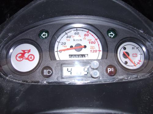
Here are some pictures comparing the XM5000Li and the XM3500Li
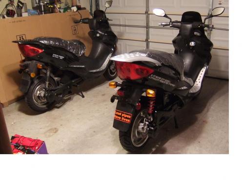
XM-3500Li on the left, XM-5000Li on the right.
Dash: XM-3500Li on the left, XM-5000Li on the right.
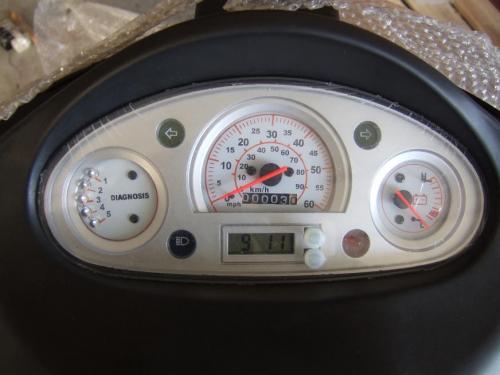
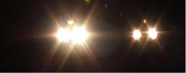
The intension of the following pictures is to show the difference in lighting. Does anyone know the numbers/types and wattage?
Low beam (at about 45 feet): XM-5000Li on the left, XM-3500Li on the right.

High beam (at about 45 feet): XM-5000Li on the left, XM-3500Li on the right.
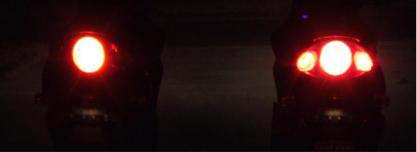
Tail Light (at about 25 feet): XM-3500Li on the left, XM-5000Li on the right.

Brake Light (at about 25 feet): XM-3500Li on the left, XM-5000Li on the right.
Dash: XM-3500Li on the left, XM-5000Li on the right.
Does anyone have any pointers on how to remove the two batteries in the bottom front of the XM-5000Li?
What is the diagnosis feature? Loud pipes saves lives... on an electric scooter,thats a good one! It would be nice to get an idea of range at 30 to 45 mph driving if anyone gets a chance on the 5000li.
Bill
2008 XM3500li Mods/Kelly KBL12251/84v 28cell 40AH pack/ Variable regen brake trigger on left brake handle/Givi/Cycle Analyst/Homemade BMS
KMX Typhoon Home build (recumbent pedelec) with two Astro Brushless 3220motors/twin castle Phoenix ICEHV 160/ Cycl
The manual only explains 1 and 2. (3 - 5 are not explained.)
1. Faulty brake switch, kick stand down or missing, or motor overheating.
2. Controller overheat protection.
Thanks for getting the "Loud pipes save lives" I had it on the XM-3500Li and transferred it to the XM-5000Li. I hope people continue to understand the humor.
I plan on doing a series of evaluations (e.g. speedometer and odometer accuracy. Maximum speed of "Economy" and normal mode. The range evaluation will probably be only for 45 - 60 MPH, unless otherwise requested.
I am in the process of laying out a PCB that will provide these main monitoring-related functions:
1. For safety, fuse each line from the cells,
2. Provide connectors to allow convenient attachment of other monitoring devices (like the PakTrakr),
3. Provide a 2.1 volt cell-too-low warning,
4. Provide a 2.7 volt low-cell warning,
5. Provide a set of simple 5.0 mm jacks to connect a voltmeter (to measure any one cell's voltage).
I hope to have a completed board in about a month.
I am still trying to get X-Treme to allow these monitoring functions without voiding the warranty. This cell-wiring and the monitoring do not change the operation of the controller or the charger in any way. So, they might possibly permit this monitoring addition.
I decided to use the 24-pin Val-U-Lok connector, with Pack-Negative at pin 1. I decided that one row of 12 pins would hold the odd-numbered wires, and the other row the even-numbered wires. Thus, wire 2 (the negative terminal of cell 2) is next to wire 1 (Pack Negative), but in the adjacent row. This way, the negative of cell "N" is on wire N, and the positive of cell N is on wire "N+1". Wires 1, 3, 5, 7, etc. connect to the "pin-1" row, and wires 2, 4, 6, etc. connect to the other row.
1 3 5 7 9 ...
2 4 6 8 10 ...
looking down at the header-recepticle connector on the PC board.
I hope to be allowed to connect the two "low-voltage" warning lines to two of the unused LEDs in the Diagnostics indicatior in the instrument cluster. That would allow the driver to reduce speed (thus reduce the load on the battery Pack) and avoid over-discharging an unbalanced cell.
I believe that some form of monitoring of the cells must be done if one wants to attempt to get good life out of the battery Pack. And, when ThunderSky comes out with an approved BMS, we will be ready to connect to it without having to take the scooter apart to add wiring to each cell.
Cheers, Gary
XM-5000Li, wired for cell voltage measuring and logging.
I forgot to mention the brake/tail light on the XM-3500Li is an 1157 bulb. The original burned out when the DC-DC Converter shorted.
Thanks, glad I could join.
The added power is nice (and puts the XM-3500Li close to what I was expectating when I ordered it.)
I charged all 24 cells (the extra 4 cells are from Elite Power Solutions) right before the ride using the TSL72-15 (87.0V/15A DC) battery charger (The voltage reading is 88.4) and the BMS from eped (A very big THANKS! to eped.)
On a different note: I had problems with two battery packs (sets of four, total of eight) using the stock 20 batteries. I originally had one cell go bad, by the time I could ship it back to X-Treme another three cells had gone bad. X-Treme replaced the batteries. The replacement batteries never fully charged (even when the charge cut off because of the completed charge, it went into the "off-on-off-on-off" mode) so the replacement batteries dropped below 2.5v (The cutoff did not engage). X-Treme replaced this set of batteries also. I commend X-Treme for warranting the batteries without a hassle. Once I received the third set, I decided to use eped's BMS and along with adding the additional 4 cells. I figured what I was doing wasn't working, so I would try something new. The problems charging the batteries were gone! Once again, A very big THANKS! to eped. All I needed to do was attach the BMS when I attached the charger and disconnect the BMS when I disconnected the charger.
Sorry I was so wordy, now to answer your question. The road is flat with no wind. The temperature was around 35 - 40 degrees. I weigh around 175 lbs (depending on how much I ate last :)) The speed (54 mph) is after riding for 3 miles. (I going down hill for the first 1.5 miles, so the charge is basically the same as when I started. I travel a total of 10 miles to work. The XM-3500Li is off for about 9 hours. On the return trip (on the same level road. I've traveled 17 miles at this point) the speed is 51 mph.
Another different note: I noticed something I was not expecting with the XM-3500Li. With 20 batteries the amperage is Max 78.4, Min -0.5 and with 24 batteries the amperage is Max 80.0, Min -0.7 (using an Ideal 61-768 meter) I was expecting the 80 amps. What I was not expecting was the negative 0.7 amps. Maybe there is a little bit (may be insignificant) of extra power. It would be enough to partially power the lights (not enough to charge the batteries).
Henry, No words are good. Can't learn without them. Yeah I almost put my new 4 cells in with the stock batts at a full charge. Then I realized that both sets had to be at the same state of charge.(SOC)Be careful though about running the pack to low. The low voltage cutoff on our controllers is 52.5v. 20cells into 52.5v=2.62v per cell which is fine it's above the 2.5v recomended LVC. 24cells into 52.5=1.87v per cell, thats below the recomended LVC so this will stress the pack. I'm using balance/monitor cards so I don't have to worry about it. My cards blink off at 3v so I just back off the throttle till I cant go any more without the cards going off. Anyway what I'm trying to say is, try not to run the scooter till the controller cuts off. When the scooter starts slowing down very noticably don't push it just find a place to charge. You may know this already but I just want to make sure.
Bill
2008 XM3500li Mods/Kelly KBL12251/84v 28cell 40AH pack/ Variable regen brake trigger on left brake handle/Givi/Cycle Analyst/Homemade BMS
KMX Typhoon Home build (recumbent pedelec) with two Astro Brushless 3220motors/twin castle Phoenix ICEHV 160/ Cycl
Thanks for the reminder on the LVC, I had forgotten it was at 52.5v.
I used the post from a while back where someone posted how to attach a 12 volt (Optima, I think) to the XM-3500Li without affecting the normal circuitry so the LVC still works as it should. I used four "TS-LFP40AHA" instead. I did find that at the end of 20 miles (normal daily round trip commute) the additional batteries voltages were slightly higher than the standard 20 batteries. This out of balance condition was managed really well by the BMS eped created. The voltage on each battery was 3.68 at the end of the charge. I find my realistic range (50+ mph) is about 25 miles (each battery is about 3 volts). The volt gauge goes below 1/2 after 28 miles (mph drops to around 43 mph) and gets really close to engaging the LVC at 30 miles.
yeah, the optima battery is a good cheap alternative. You can fit two of them under the seat. WE tried this for awhile. We hooked them up in series for running then took them out of series for charging(takes 2 minutes maybe)but the optima is 38AH which is a problem when the pack is getting low. We have run the 3500li with a pack at 105v full charge without a problem. However I WOULD NOT RECOMEND THIS... after doing the solder wicking mod (in another post) on the controller my friend fried his controller doing a fast start from a stop. However I wicked two of the shunts on my controller and got much better pickup but it doesn't seem to effect the top speed much.(and nothing has blown so far) I love mine despite it's minor flaws.
Bill
2008 XM3500li Mods/Kelly KBL12251/84v 28cell 40AH pack/ Variable regen brake trigger on left brake handle/Givi/Cycle Analyst/Homemade BMS
KMX Typhoon Home build (recumbent pedelec) with two Astro Brushless 3220motors/twin castle Phoenix ICEHV 160/ Cycl
Well, I found a minor "design problem" with the 5000Li:
The implementation of the mounting bracket for the License Plate.
1. In trying to mount the California license plate, if one tries
to center the plate, the mounting holes did not match.
So, just drill new holes, right?
Slightly difficult, since the two new holes need to be right on
two of the four slight bends in the bracket.
Why are these bends there at all?
Presumably so that the mounted license plate will clear the heads
of the bolts that attach the bracket to the rear fender.
But ... the slight existing depression made by the bends is insufficient
for the plate to clear the bolt heads. The depression needs to be at least
twice as deep, or, for good measure, make it three times as deep.
And, put the bends further inboard so the mounting holes can be used.
So, I re-bent the bracket, although somewhat crudely, since I do not have
the proper tools to do the job, and my wife was unlikley to let me buy
a sheet metal "brake" just for this job. (grin)
Now, the mounting holes in the bracket can be used to mount the plate.
Cheers, Gary
Cheers, Gary
XM-5000Li, wired for cell voltage measuring and logging.
Andy,Gary, Are you guys having any luck getting your cells close to a 3.7v average?
2008 XM3500li Mods/Kelly KBL12251/84v 28cell 40AH pack/ Variable regen brake trigger on left brake handle/Givi/Cycle Analyst/Homemade BMS
KMX Typhoon Home build (recumbent pedelec) with two Astro Brushless 3220motors/twin castle Phoenix ICEHV 160/ Cycl
A 3.7 v average is not good. One cell at 2.7 and another at 4.7 would be a 3.7 average.
What you want (of course you know) is all cells at the same near-full State of Charge (SOC, or "fullness"), all near "full".
If one starts with the cells nearly balanced, the 5000Li TS smadt pulse-charger MIGHT keep the cells balanced, we are not sure.
Starting with the cells not balanced, as delivered, it APPEARS that the TS charger would be likely to overcharge the higher cells. We have not wanted to sacrifice our own batteries to do the test.
Without a BMS type function to protect each cell from overcharging, it seems unlikely that any two-wire "Pack-Charger" can avoid over-charging a high cell.
Using a voltage-activated shunt to bypass charging current (or other protection) seems to be a necessity. A simple half-amp shunt used with the TS charger seems to do a good job as long as the imbalance is not too large. With a large imbalance, the initial 14-amp charging could still over-charge a high cell.
Manual charging of single low cells will help (but would void the battery warranty), so manually discharging high cells before doing any "pack" charging might be necessary.
However, adding the required 22 wires to the 21 cells, just to be able to CHECK the cell voltages is a SIGNIFICANT job, and might possibly (hopefully not) void the warranty. Monitoring and checking the voltages does not change the way the cells are charged with the TS charger.
Cheers, Gary
XM-5000Li, wired for cell voltage measuring and logging.
The opinions expressed by certain members of this site are not specific in knowledge nor transferable nor meaningful in any way shape or form:
Re: Warranty, are you really serious that Xtreme is going to know what you have or have not done to your bike? Are you going to ask them permission before you do anything? Do you really think that if your controller dies because of a fault of there own that they will come to your house and fix it for you? Do they have little birds like Santa Claus does looking in the window of your garage and taking names down as to who is a naughty forward thinker EV'er and who are sheep? This is the company that advertised a BMS system and Regen Brakes and did not deliver them nor offer a discount nor apologize to every XM3500 owner out there. To make up for the BMS snafu they have put a warranty of 2 years on your batteries. I would assume that once we keep flooding them with burned out batteries they either will replace as they promised or will ignore us, or develop a workable BMS system and Sell It To We/Us who were promised it in the first place. WE on these pages are the ones doing all this research and development, WE ARE YANKEE INGENUITY AND THAT IS WHAT IS HAPPENING ON THIS SITE. We are taking the ball (finally) into our own hands one step at a time and making this burgeoning technology happen. The Chinese and Alpha are there to make money at their risk and we are readily happy to comply. However WE want more speed/distance/reliability/communication and any warranty will not stop me/us from getting all of those improvements for ourselves and SHARING WHAT WE LEARN WITH OUR FELLOW EV'ERS registered on this site.
End of tirade and rant....as always (keep up the forward thinking and risk taking) Best Mikie
mikie
Pages