I know someone (probably Mik) published the battery pack currents for various loads, but I can't find the information again.
Have been thinking about replacement batteries again and it seems the 24, 36 and 48V lithium packs from manufacturers such as Ping are quite limited in discharge currents.
So I wondered how many strings of (10, 15 or 20AH) packs in parralell would be required to supply the peak currents that the original NiMH cells can provide. Quite easy to do the capacity calculations and then work out if the resulting series/paralell packs will fit in the 700 x 330 x 230mm battery bin.
If for instance, a continious current of 80A and a maximum of 120A peak is sufficient, then two strings of 6 x 24V 20AH LiFePO4 Ping packs would fit in the existing VX1 battery bin, with room for seperatots to allow cooling air flow. All this for about $8530 Australian.
Charging is an entirely different matter, which I don't want to think about at the moment.
A simple calculation of power devided by volts indicates however that at 16kW and (nominal) 125V then 128A would be required to push the Vectrix along.
Just need to know the currents provided by the old cells.

Some of it here: http://visforvoltage.org/book/ev-collaborative-hand-books/6916#comment-40025
But someone (?X-Vectrix?) wrote in another thread that the actual current peak is much higher, something like 320A IIRC. Cannot find it right now.
This information may be used entirely at your own risk.
There is always a way if there is no other way!
Up to 220A (or 320A)!
Ping will not work. Back to the drawing board.
Thanks Mik.
Cheers
Paul
Here it is: http://visforvoltage.org/forum/7002-possible-future-vectux-open-source-vectrix#comment-41261
375A (265Arms).
60A at full throttle once top speed has been reached.
A bit furthr down x-Vectrix wrote:
Could anyone explain this a bit further, please? If the IGBTs are always firing at 15kHz, then why does the CANBUS current draw show low currents off the line and a current peak at 76km/h? Why is it not regulated in such a way that the maximum current can always be drawn?
You hear again and again how EV's have all that torque off the line - why not the Vectrix? What is different about it, which part would fry if maximum amperage was permitted off the line?
This information may be used entirely at your own risk.
There is always a way if there is no other way!
http://www.kokamamerica.com/kokam_catalog.pdf
Page 10, High Power cell, 40Ah, 5C Continuous, 10C Pulse.
38 of those cells should be perfect for Vectrix (size and specs). I've already done all the calculations. I had to, because I didn't know whether I will get my battery replaced, when mine failed this spring.
This pack should weigh 1/2 of current NiMH pack + give more capacity. Current charge/discharge software should work with the pack of 38 cells.
The maximum phase current is drawn at 0mph because the back EMF of the motor is near zero. Very little bus current is needed because the phase winding looks like a dead short to the battery voltage (which is applied in short pulses by the IGBT and smoothed out by the windings). As the motor speed up the BEMF increases, so to keep the phase current steady the IGBT has to stay on longer which is seen as more bus current.
The phase current is limited to about 375 A peak. This limit is a factor of the IGBT specs and how fast you can remove heat from the IGBT. It comes down to $$. These IGBTs are very expensive. You could use one that allows twice the current but the cost of the controller would also double. As is, the scooter draws near the limit of the battery current. So bigger IGBTs means you need bigger batteries...again, more money. Oh yeah, and you decrease your range.
A common issue with the Sparrow and NMG Evs is too much power on takeoff. Owners have to learn to be easy on the pedal to avoid ripping the pully from the rear wheel or popping the drive belt. I expect that if the Vectrix had full power to the hub at all times, you'd have trouble keeping the tire on the rim, or you'd be replacing rim-to-hub bolts frequently. Too much power is just going to spin the tire or rip something apart.
Hi Paul,
Just saw your query re battery current drawn by the Vectrix.
Whenever any tries to tell me that the Vectrix draws over 120 amps I start to wonder where they get this information. I well appreciate that Vectrix gave the motor Specs and told us all about Peak Power being 21 kWatts at the motor shaft BUT that is NOT what the Vectrix does. Vectrix maximum current is about 110 Amps. Think about it, The fuse carrying this current from the battery to everything is 125Amps..
I have taken the trouble to measure the current drawn at different speeds, loads and accelerations. Unfortunately I don't know how to 'paste' this information so here are a few figures from the charts.
At 20 Mph on a level road current drawn = 10 Amps
At 30 Mph on a level road current drawn is 15Amps
At 40 Mph on a level road current drawn is 25Amps
At 50 Mph on a level road current drawn is 40 Amps
At Maximum Power on an incline from standing start and full 'throttle'
current drawn is 106 Amps.
By the way, NiMH batteries should not be discharged at more than 3C and preferably a lot less. Which explains some of the problems associated with the Vectrix battery failures.
I hope that this helps.
The above figures were obtained in good calm conditions and a warm day (20 degrees C).
Thank you for this very informative post.
My guess, before your post, was that the sweet spot for 1C discharge is around 70km/h, and I guess I was very close.
With my second battery pack, I limit my speed to 70km/h and drive 80km/h only if really necessary. I accelerate as gently as possible considering the traffic at the time.
High discharge currents are also the main source of cell imbalance (considering all cells have the same capacity).
Cell's internal resistance is never the same from cell to cell and higher the current, higher the difference in internal resistance -> higher temperature difference between cells -> even higher internal resistance, which causes cell discharge imbalance. At 102 cells and no balancer, this is a definite.
http://www.batteryuniversity.com/partone-16a.htm
It's really unfortunate we can't get (from any spec) the Peukert number for Vectrix's NiMH battery pack.
A lack of an active balancer is the root of Vectrix's battery failures. But for 102 cells it would be very expensive.
LiPo or LiFePo pack with an active balancers (since the cell voltage is higher, there are less cells needed, thus the lower cost of the balancer) is a must for the New Vectrix and our upgrade.
A full throttle acceleration from a dead stop will draw over 200 Amps by the time you hit 60 mph.
How come there was only a 125A fuse installed, initially?
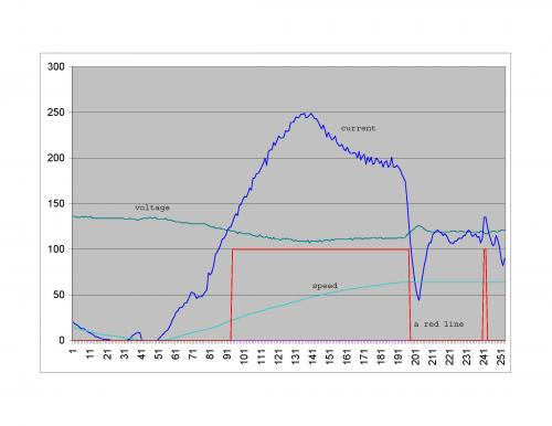
Edit: Does 'a red line' represent the time, when the current is over 125A?
I still don't get it: Why is it not possible to draw much higher current at speeds below 76km/h?
Trying to understand multi-phase power circuits is putting a knot in my brain...
Is this delta or Y-configuration, for starters?
Or do you mean to say (in the earlier post above) that the phase currents can be higher than the line current? (Line current = current out of the battery and phase current = current through either of the three IGBTs and the three cables between motor controller and motor, right???)
Is the maximum phase current through an IGBT (375A) being reached whilst the line current is only, say, 50A at about 17km/h during a full throttle acceleration?
This information may be used entirely at your own risk.
There is always a way if there is no other way!
Hi All
Am impressed with the amount and quality of responses to my enquiry.
A few further questions:
Laird, how did you measure the battery currents? Did you use a DC clamp meter or a shunt and millivolt meter? Why are the numbers so different from Mik and XVectrix's figures?
Vectrix motor controller clearly limits the current draw to protect the battery/ controller/ motor system. Currents seem to be measured and the CAN system can be interogated to free up this information. It seems a little unclear to me if the published data is from motor currents (AC) or battery currents (DC).
Correct me if I am wrong, but there are CT's on the motor controller board at the motor terminals. Where and how is the battery current measured?
As for the fuses: I know that HRC fuses will typically not rupture till 120 to 180% of rated capacity (depending on manufacturer and specifications). The fuses will also be stressed by continual exposure to over-current. So it seems to me that the very high currents (up to 370A) mentioned br XVectrix and Mik, will not immediatly pop the original 125A fuses. High currents will stress the fuse which will pop some time later.
Thanks for the lithium cells link, more to think about.
Cheers
Paul
Motor must be connected in delta if phase current is higher that line current.
To calculate line current, devide phase current by square root of three. So for 375A phase current, line current must be 218.4A.
Isn't that the maximum current from your figures Mik?
Current limit at low speeds = no burnouts!
Paul
the phase current is current going through the motor.
line current is the same as battery current.
at all times, phase current > battery current.
basically the controller acts as a buck converter aswell as a dc-ac converter.
so it steps down the pack voltage to whatever voltage the motor needs at the time.
so current out is greater than current in.
at 0 speed, motor voltage is say 1v.
at max phase current of 375A * 1.73 for imaginary between the phases, thats 648w electrical (but 0w mech due to no movement).
so battery side current would be 648/125 = 3A.
if you want to dump more power to the motor, the phase current has to be increased. This requires bigger power silicon.
a higher speed, motor voltage would be 65v
at 375A phase * 1.73 * 65v = 42kw
battery currrent = 337A.
This is beyond the programmed max battery current so the controller actually only applies ~240A phase current.
at peak power, battery voltage = motor voltage (simplistically speaking. actually its peak voltage between the phases = battery voltage).
at this point the controller no longer has any more voltage headroom to be pushing max amps through the motor, so power starts to fall. Even though the controller is in no porgrammed limit.
a 125A fuse has alotta thermal capacity. the blow rating at 250A for instance is like 30 sec.
Matt
Daily Ride:
2007 Vectrix, modified with 42 x Thundersky 60Ah in July 2010. Done 194'000km
starting in delta is something you only do when dealing with a motor that is operating direct online to the grid.
in an ev, you just leave it connected in star, unless you designed it with insufficient DC bus voltage.
phase current is the current on a single phase.
to calculate line current *mutliply* phase current by sqrt(3) or 1.73.
multiply this by the voltage between the phases to get power.
to calculate battery/bus current, divide by battery voltage.
Daily Ride:
2007 Vectrix, modified with 42 x Thundersky 60Ah in July 2010. Done 194'000km
The graph shown looks like throttle was backed off at 70kmh, ie the user only wanted to accelerate to 70kmh.
given the peak power of the vectrix is higher up (i know mine is closer to 80kmh according to my ass dyno), the peak shown is probably low.
It also looks to be values taken from the CAN bus
Matt
Daily Ride:
2007 Vectrix, modified with 42 x Thundersky 60Ah in July 2010. Done 194'000km
Thanks, I think I got it now, sort of...
That means that a full throttle acceleration takes the IGBTs to the limit each time, even if the battery has little hard work to do if the acceleration stopped at about 40km/h.
That's why the motor controller cooling fan is howling like a banshee at the top of my driveway....slow speed, steeply uphill means low resistance of the motor coils, low voltage and max current through the IGBTs when I give it full throttle. That makes the IGBTs very hot, although the battery did not have to deliver all that much power.
This information may be used entirely at your own risk.
There is always a way if there is no other way!
Yes, 218A is the reported max current on the canbus:
That makes me wonder if X-Vetrix' explanation about the 15kHz and 1Hz bus sampling rate is correct - or maybe I still dont understand this.
But 218 * sqrt3 = 377 ; that looks to me like the canbus reported current is the line current.
This information may be used entirely at your own risk.
There is always a way if there is no other way!
It looks like a full throttle acceleration to top speed to me. (You are talking about the graph X-Vetrix showed above?)
This information may be used entirely at your own risk.
There is always a way if there is no other way!
The phase current is the current going thru the motor which is Y connected. This is instantaneously equal to the current from the controller on the battery side. I say "from controller" because there are bus capacitors that provide bursts of current when a phase is pulsed. The current from the battery then recharges these caps. Its fast and the pulses are short so you will not see it without a fast current probe. The IGBT switches the full battery voltage to the windings at all times. The current is controlled by varying the width of the pulses. 5-10 usecs at low currents to 50-60 usecs at full current. Since the motor is an inductor, when the IGBT current is switched off, the current thru the phases does not immediately fall, it fades, but along comes another pulse to bump it higher. The pulses can be controlled like this to generate a sine wave current through all three phases separated by 120 degrees. The peak of this sine wave is limited to 375Amps. So, this does not mean that at this peak phase current there is 375A being drawn from the batteries. Its a succession of pulses thru the IGBT that add up to the peak phase current.
As the motor speeds up, the BEMF is fighting the flow of current thru the phases (windings) so the IGBT stays on longer to provide the boost of current that will increase the affective phase current. If the BEMF is high enough the IGBT can no longer provide the current and the system cant produce more torque.
You can play some games with the placement of the field in the stator to overcome this BEMF, Its called phase advance or field weakening. Normally you place the field in the stator 90 degrees ahead of the rotor field to provide maximum torque. Unfortunately, this is also where the peak of the BEMF is. By phase advancing, the field in the stator is placed at greater than 90 degrees ahead of the rotor where the BEMF is lower and more current can flow. The drawback is that you lose torque because the stator field is not at 90 degrees. Eventually, tho you cant produce more torque.
The throttle wasnt let off in the graph. The speed limiter kicked in so the acceleration stopped. The current on the right is the current to maintain the scoot at 62mph, which was into the wind and on a slight incline, and is higher than what it normally takes to maintain 62.
Those values are mph, not km/h.
Hi Folks,
I think that the arguments concerning the Current drawn by the Vectrix are wonderful.
There is confusion, lets clear that first.. The currents circulating in the motor windings are NOT the same currents as drawn from the battery. Due to the action of inductance, resonance and capacitance, there will be considerable differences between the D.C.current supplied by the battery and the currents circulating in the motor /motor controller circuitry.
When it comes to the problems of battery longevity, the only concern is the battery current. The rate at which that current is either taken from the battery (discharge) or put back into the battery (re-charge), the state of charge of the battery I.e. full, part empty or empty, the temperature of the battery and the ambient temperature, these are the details that count. So, forget the enormous currents zipping around the motor, forget the motor control circuitry and get your mind back onto the only problem which we face, which is:- The total cock-up made by the engineers at Vectrix when they programmed the bikes computer which controls the activities of charging and riding the bike.
I have been working on the batteries and the charging techniques for the past three weeks, I have nearly finished my investigations and am in the middle of testing a method of balancing the cells with minimum of disruption to the bikes wiring. When I have a useful result, I will publish it here on the forum and perhaps we can all get some rest.
Incidentally, the 106 Amps Drawn at full throttle and quoted in my earlier post were taken from a memory dump following the test ride. For those who wish to know the detail this is how it was done, here it is:
Prior to the test run the bike was switched off. (this produces a new item of data within the bike's memory)
the bike was switched ON and immediately power was available (one/two/three seconds?) the throttle was swung wide open.
The bike took 27 seconds to reach 62 MPH and at the moment that the bike stopped accelerating the switch (ignition?) was turned off (thus completing the memory item and storing it)
The memory dump gave the following results:
Minutes = 0.45 (27 Seconds)
Distance = 0.22 Miles (387 Yds)
Amp Hours = 0.80
Average current 106.53 Amperes.
Yes, there could have been a delay in my applying the throttle after power-up. If you recalculate using say a three second delay you will still only get 120 Amperes Average.
Granted, a fuse does not necessarily blow at it's rated current and depending on it's type / designation it will survive overloads. I did some work testing fuse ratings and their actual failure currents for a variety of types and yes, overloading a fuse always leads to failure. The amount of overload and the type of fuse simply determine the time required for that eventual failure.
I think that that should answer most of the difficult questions and solve some of the puzzling statements which this forum has carried recently.
I hope to post again soon.
The Laird.
P.S.
I forget to mention. That 27 seconds to do from 0 to 62 Mph, I picked a handy long road with a regular slope in order that I would be able to get a 'long time' run at full throttle for greater accuracy.
Sorry, I should have mentioned that.
The Laird
If I were a betting man, Id put my money on the graph as an accurate representation of the VX1 battery current.
BTW. What is a "total cock-up" ? Is that a good thing or a bad thing?
things like this im guessing?:
insufficient temp compensation during charge (voltage)
ineffective method of measuring capacity
no "full charge" Ah compensation with temperature
its nice to know where that 106.5A number came from.
if its the average over a 0-60mph acceleration, its believeable.
certainly doesn't show max power, but does show how close the original fuse rating is to the minimum required.
Matt
Daily Ride:
2007 Vectrix, modified with 42 x Thundersky 60Ah in July 2010. Done 194'000km
Here is a video showing the RETAMPI (Real Time Amp Indicator) during a full throttle acceleration on flat ground, followed by full regen braking back to standstill.
The RETAMPI is calibrated to peak at 100 (mV) and shows the percentage of current going through the main positive battery cable to the MC.
The RETAMPI gets the measurement voltage from one of the hall effect sensors on the MC board.
This RETAMPI measurement is consistent with the graph shown by X-Vectrix, I believe.
http://s281.photobucket.com/albums/kk217/Mr_Mik/Vectux/RETAMPI/?action=view¤t=RETAMPI100mVacceldecelaccel.flv
See http://visforvoltage.org/forum/3747-vectux-part-3-vectrix-retampi fpr original context of the video.
This information may be used entirely at your own risk.
There is always a way if there is no other way!
I would love to know how you view the information from a memory dump. I have the canbus tool and sw and see the memory dump option, but have no idea what software is used to decode the memory dump. Can you please explain how you viewed the memory dump?
Thanks,
Peace upon you,
The argument rages on.
X Vectrix's post of the graph shows a current drawn which exceedes 200 Amps indeed, it shows a maximum of 250 amps, assuming that the scale on the left represents the current in Amps. Unfortunately there is no indication of the X-axis scale (the horizontal scale) which rather leaves the graph as being worse than useless in this context. I suspect that the current curve is actually that of one of the motor phases, probably over a short time period of milliseconds. I will no doubt stand corrected in due course.
A 'total cock-up' refers to the practice of 'getting something as wrong as it could possibly be'. Vectrix have got the battery control ALL WRONG.
Mik's mention of his RETAMPI and his agreement with X Vectrix. I cannot find any reference to the actual current values. Mik's RETAMPI refers to 'percentage' of maximum but does not state current value. I am not in the business of discrediting anyones work but I do feel that to some extent we have 'lost the plot'.
The whole sad business of the Vectrix failures (discounting the build quality) is all related to the battery failures which are consistent throughout the production run. No one has ever got anywhere near the original claimed 50000 miles per battery pack, from what I hear and from personal experience, between 2000 and 8000 miles would probably represent a truer figure.
Back to the problem. The battery pack is suffering from 'short life'. The battery problems are related to an imbalance between the battery cells. The imbalance becomes worse with time and usage. The Vectrix charging system has no means to correct the problem. This, as I see it, is the problem which we will all face sooner or later and this is the problem that we need to 'fix'.
When considering the current drawn from the battery, we can, to a large extent ignore the controller circuitry and motor, indeed we have to ignore these items because no one has any detailed knowledge of either of them. Without a data sheet on the motor we can only guess on it's efficiency (which in some of these motor types falls to less than 40% under specific running conditions) We do not have any data concerning the efficiency of the power control system either and we can safely guarantee that it will be less than 100%, but by how much?
The battery current will on average not exceed the fuse value or the fuse will break, that's what fuses are for. Pulse current values may exceed the fuse ratings for short time periods, but the average current realy should be at, or less than, the fuse rating / value.
Now, if we can return to the question of 'how much current does the vectrix draw from the batteries' which was Paul's original post. I think that the answer is "up to 120 Amps, probably not more than 110 Amps". We are talking of D.C. and by definition storage batteries are built to provide D.C. which is a current of steady voltage and steady current. If you insist on taking the current from the battery in 'pulses' i.e. high speed varying amounts of current, then you are using a D.C. supply to produce an A.C. (alternating current) effect. This is NOT what batteries enjoy and is really a form of serious abuse. However, this is what we have got and this is what we must make the best of.
Having settled the question of how much current the battery provides and hopefully, pacified the snippers out there, can we get back, as a team, to the finding of a 'solution' to the vexed question of how to maintain the Vectrix battery despite the complete lack of help from the Vectrix manufacturers?
I, for one, am doing what I can to solve the problem as I see it. As soon as I have a positive result I will post my findings right here on the forum and perhaps we can all benefit.
In the mean time, for those wishing to have a deeper discussion of the motor and motor control hardware efficiencies, problems and solutions, can I suggest that this is a separate topic and, as we have little or no data, the discussion will have to be on a purely hypothetical basis.
The Memory dump. In addition to the 'Scooter Diagnostic software' and 'CanBus adapter' you would need a copy of the 'microsoft Spreadsheet template' as used by Vectrix. Onto this sheet you can 'paste' the results of the memory dump and there you have it.
On the 'memory' page and in the 'memory dump' box put in the address and size.
The address for the memory dump is 0
The size is 0x800.
Put in those values and 'press' the 'start' button.
The memory dump when complete asks for file name and the result is a 'cvs' file.
Open the file with your spreadsheet (Open Office or Microsoft office)
Copy the contents of the first column (control-copy)
Paste the 'copy into the first column of the Vectrix 'Template'
and read the results.
This does take a little deciphering but some useful information is present.
DISCLAIMER - I have no wish to offend anyone. My sole interest is in solving the problems which the Vectrix designers have left us all with. My impression is that we are missing the point and wasting time and effort hence my 'attitude' as demonstrated in this post. If anyone can provide me with a copy of the software that was used to write the vectrix programs I could solve the bulk of the problems (possibly all of them) within a week. Come on people, I'll even accept a 'pirate' copy of that software.
The Laird
Hi Laird,
you are getting a bit, sort of, carried away there....
What is the problem with discussing the battery current and the motor currents at the same time?
We have no data??? Nonsense, we have plenty of data, and the graph shown by X-Vetrix is a prime example of how we get NEW data all the time. I wonder how exactly it was made, rather than attack it for no good reason.
The reason why I say the RETAMPI data are consistent with the current curve shown by X-Vectrix is because the shape is the same. I have not been stubborn enough to actually work out what current is indicated by what voltage (between 0 to 4.5V) that is produced by the hall effect sensor around the positive battery cable; that's the reason why I calibrated the RETAMPI to peak at -100mV. That way it shows the percentage of maximum possible current draw from the battery (and positive values for regen braking and charging).
Combine this with the clear CANBUS messages, showing a 218A peak at 76km/h at full throttle, which is exactly the same peak-speed as the -100mV RETAMPI peak, and the peak-speed in X-Vectrix curve, and the formula 108V*218A=23kW, which is very close to the claimed peak power of the Vectrix motor, and all the so far available evidence says that you are wrong with your current estimate. It's way too low!
Your main argument seems to be that the fuse is too weak for the 218A current - of course it is, thats probably one reason why the fuses keep failing and were replaced with 200A fuses later on!
I think the X-achsis in the graph is in seconds/10.
None of this is contradicting any of what you say about the battery problems, by the way.
I could not give a toss if it is exactly on topic with the initial title of the thread, it's very interesting, anyway!
This information may be used entirely at your own risk.
There is always a way if there is no other way!
Pages