OK, I've given up on putting the 1:1 isolating transformer into the same box with the rest of Freddy (for now...).
Hopefully all the other problems have been addressed in the following schematic:
1) All motor run caps discharge separately or together. The losses are actually reduced by switching the discharging resistors on only when needed.
Only problem remaining in this regard is that if the transformer was turned off, or grid power fails and comes back on a little later, the motor run caps would still be charged.
2) Leaving each second position of the 12p rotary switch unused should increase it's voltage rating drastically. The 1k Ohm resistors will limit the current to a max of 170mA through the switch (if it is set to 2V range during actual 340V)
3) Adding another two electrolytic caps should reduce the ripple further...I hope...
4) A switched shunt, rather than 2 ammeters.
5) Voltmeter measuring battery voltage without the drop caused by the diode.
Do you think this would work?
.
Click for larger diagram:
This information may be used entirely at your own risk.
The rotary switch problem was that the resistors (attached to the rotary switch) not in use would carry very different voltages to the ones connected through the switch. these voltages could cause arcing and/or insulation breakdowns. It is a safety issue.
The voltage on an open ended resistor is the same at both ends. Looking at the diagram the open ended resistors would have near zero volts whilst the one connected through the switch might have the output line voltage. Resistors also have a voltage ratings. In a 300 volt circuit use at least a six hundred volt resistor (x2 safety factor).
The current variations with mains fluctuation is because you have very few volts to drive current into the battery at the voltage you require for the Prius battery. Consider the voltage difference between the charger output maximum( 339volts) and the voltage of the battery on charge (I think you quoted 334volts) there is not a lot of volts left. Any variation in the mains will have a substantial effect on the charger output voltage and current.
The new circuit looks good. BUT I think that you may have read my 'motor run capacitor discharge resistors' wrongly or perhaps, deliberately changed them.
The values suggested were
for the 4 microfarad capacitor a 2.2M Ohm at 1/4 Watt (min)
for the 8 microfarad capacitor a 1.0M Ohm at 1/4 Watt (min)
for the 16 microfarad capacitor a 470K Ohm at 1/2 Watt (min)
for the 30 microfarad capacitor a 250K Ohm at 1 Watt (min)
The lower resistor values you have used will speed up the discharge but increase the power losses as you have found.
The 14Kohm at the bottom of the capacitor bank seems 'redundant', I must be missing something.
The output doide will need to cope with the potential short circuit current, I trust that it is a high current type, over 5amps and preferably 10amps at 600 volts minimum preferably 1000volts.
Mik, your electronics knowledge is increasing in leaps and bounds:-)
Thanks again for helping me with this, TheLaird! Much appreciated.
Hi Mik,
The rotary switch problem was that the resistors (attached to the rotary switch) not in use would carry very different voltages to the ones connected through the switch. these voltages could cause arcing and/or insulation breakdowns. It is a safety issue.
Can arcing be caused although the maximum possible current is just 170mA? I don't know, but I imagine that a higher current is needed to allow an arc to form???
The voltage on an open ended resistor is the same at both ends. Looking at the diagram the open ended resistors would have near zero volts whilst the one connected through the switch might have the output line voltage. Resistors also have a voltage ratings. In a 300 volt circuit use at least a six hundred volt resistor (x2 safety factor).
I'll have to check what voltage rating my resistors have. This would also affect the 1MOhm resistors in the original design, so I might have to change them. I might have to physically remove the copper parts for the 6 unused poles of the switch, that will put such a large distance between them that it cannot arc.
The current variations with mains fluctuation is because you have very few volts to drive current into the battery at the voltage you require for the Prius battery. Consider the voltage difference between the charger output maximum( 339volts) and the voltage of the battery on charge (I think you quoted 334volts) there is not a lot of volts left. Any variation in the mains will have a substantial effect on the charger output voltage and current.
I actually get higher voltage here. The mains voltage is often around 250V, and the 1:1 transformer seems to add a few volts on top of it!
But the action on the Prius batteries is taking place in the top right corner of the graph you showed above (second post or so). With the large motor run caps (30+16microF) there is another straight line that starts at 255 * 1.414 = 360.57V ; but it crosses the X-achsis about 2.5 meters to the right, at around 5A!
So a variation of 5V (due to e.g. an air conditioner turning on) can cause a variation of 30% of current flow; but just in that top left corner of the curve. If 4A were flowing, it would also drop by 0.1A and would be hardly noticeable. That took me a while to figure out!
The new circuit looks good. BUT I think that you may have read my 'motor run capacitor discharge resistors' wrongly or perhaps, deliberately changed them.
The values suggested were
for the 4 microfarad capacitor a 2.2M Ohm at 1/4 Watt (min)
for the 8 microfarad capacitor a 1.0M Ohm at 1/4 Watt (min)
for the 16 microfarad capacitor a 470K Ohm at 1/2 Watt (min)
for the 30 microfarad capacitor a 250K Ohm at 1 Watt (min)
The lower resistor values you have used will speed up the discharge but increase the power losses as you have found.
The 14Kohm at the bottom of the capacitor bank seems 'redundant', I must be missing something.
The changes are deliberate. The idea is that the resistors for the individual M-R-Caps (MRCs) will only be needed when they are actually turned off. That reduces losses during operation, and allows to overload the resistors for the few seconds they are being used when an individual MRC is turned off.
I reduced the resistor values to 1/10th of your design, guessing that will shorten the 8s you designed for discharging the initial 8microF MRC to 0.8s for each MRC.
So, if the wrong switch is flicked off and the operator sees that the current dropped too far, no damage will be done because the MRC will be sufficiently discharged in about 1/2 of a second. By the time the operator realizes the error and flicks the switch back on, it will be safe to do so!
The 14K Ohm (2W) resistor is there to allow discharging of some or all MRCs in case the main power switch is turned off. The MRCs would otherwise remain charged up.
The remaining problem is that in case of power failure, or turning off the 1:1 iso Transformer, the MRCs remain charged. But I woke up with a few ideas rumbling around my head about this. It involves a 12V (DC?) power source; a momentary on switch; and a relay with the coil connected to one of it's switched output poles so that it remains on once the momentary on switch has been pushed. If power fails, or the transformer is turned off, the charger does not automatically come back on and the charged MRCs will do no damage.
Can relays be switched using 240V AC? That would make it much easier than adding in an old 240V to 12V switcher, I'm sure I've got one lying around.
The output doide will need to cope with the potential short circuit current, I trust that it is a high current type, over 5amps and preferably 10amps at 600 volts minimum preferably 1000volts.
I'll use several in parallel, 100V / 6A rated. The "Use a bigger box for prototyping" rule at work again!
Mik, your electronics knowledge is increasing in leaps and bounds:-)
The Laird
Yes, thanks to all the help from you and the other folks around the net! It's great fun!
[/quote]
This information may be used entirely at your own risk.
Can arcing be caused although the maximum possible current is just 170mA? I don't know, but I imagine that a higher current is needed to allow an arc to form???
to my (little) knowledge, the higher the voltage differential, the bigger (longer) a spark can be.
amps have no influence.
greets
t
"doing nothin = doing nothing wrong" is invalid when the subject is environment
I have one doubt. Are the batteries hurt with the normal equalization of 3A with cold weather (10-20ºC)? I mean, the stress of batteries only affects them when they reach more then 30ºC or it’s always negative?
Well, a spark is quite normal when any switch is closed at 360V.
An arc is a sustained spark, and that takes a bit of current! I just don't know how much!
to sustain an arc, it takes a lot of current indeed, going up with the distance (length of the arc)
With static electricity (sweaters etc), you can create long sparks (high voltage), but not sustain an arc (due to virtually no current).
in your case, a rotary switch could create an arc when turned off (quite normal yes), the voltage determines the length, the current determines the damage :-)
many switches have a balancer (? -I don't know the exact terminology) that cuts the contacts faster than what you could do yourself.
"doing nothin = doing nothing wrong" is invalid when the subject is environment
Following the input Isolating transformer, you will need a fuse of value 5 amps min (preferably 7 to 10 Amps).
I cannot read the V.A. rating of the transformer. It must have a secondary winding capable of the full circulating current of 4.56amps, that would require a V.A. rating of 1250VA.
It is the circulating currents that count, not the power output. With these high (4.56 amp) circulating currents, the transformer losses are equal to I x I x R (where R is the winding resistance) and the secondary wire is having to carry that circulating current of 4.56 amperes.
My 1:1 isolating transformer has only a 500VA rating. That is why I plan to put a 2A fuse in it. I actually need to read the brief manual for it again, there was something about that the thermal fuse inside the windings can blow due to a mild overload which will not blow the replaceable fuse of the transformer. I intend to put in a smaller replaceable fuse so that it will blow first!
Does this mean the circulating currents are flowing through the secondary windings of the isolating transformer even if there is no current taken out of the DC side of the charger (open circuit at full voltage)?
If that is the case, then I wonder why the transformer did not get hot at all, not even warm, during 26 hrs of continuous operation with 16+30microF MR caps and an output voltage of around 345V? The fuse did not blow, either!
I'll check again what fuses are in there and will measure AC current between transformer and charger with my clamp meter next time.
So far I was assuming that only the middle of the charging output curve would spell trouble for my undersized isolating transformer, because that's where the power is.
Yesterday I charged a Prius NHW10 half-pack of 120s NiMH cells with the 16microF MR Cap for about 12 hrs, at about 0.6A @ 172V; the transformer got only a few degrees warmer than ambient temperature.
EDIT: I had a look inside the transformer: It has a 5A fuse, which I have now replaced with a 2A fuse.
The manual warns against exeeding the maximum current rating, but does of course not tell you what that is! But on a label on the toroid I found the specs for the secondary winding: 2.1A . The thermal fuse is a 128degC fuse, not accessible.
The warning in the manual: "An overload condition is when current drawn by the appliance is above the transformers rated current but slightly less than the external fuse rating. Under this condition the transformer will keep operating until the thermal fuse blows due to overheating caused by the overload condition."
Slightly less in their world means 2.38 times overload! And, of course, it voids the warranty! That's why I've now replaced the fuse with a 2A fuse.
But as I said, the transformer did not heat up significantly and I checked it often!
This information may be used entirely at your own risk.
The maximum circulating currents would actually occur when the output voltage is lowest i.e. a short circuit or a very low voltage output. In this condition the power factor would be very low and the circulating currents very high. (4.6 amperes Max)
At maximum voltage (and zero current) output there would be no currents circulating in the capacitor or transformer secondary. The simple rule is "the current is the same in all parts of a series circuit" and here the transformer capacitor and load form a series circuit.
At about half maximum output voltage (using 240 volts as supply voltage and 340 volts as max output)) the power factor would be around 0.76 giving a phase shift of some 40 degrees (current leading). Impedance of the circuit would be 105 ohms. Real power input would be 390 Watts and output to the load (battery) 390 watts. The value of the 'leading' current, at the capacitor and transformer, would be 2.3 amperes from which the apparent power (the VA) would be 552 watts (the difference between the apparent power of 552 watts and the REAL power of 390 watts is accounted for by the power factor and Phase difference. (You really are testing/de-rusting my knowledge:-))
On balance, the simple way of looking at it is, that the current output is equal to the circulating currents at the transformer and capacitor, with the capacitive phase shift 'losing' the un-required voltage difference between the input (mains) and output(charge current).
The transformer is inductive and will generate heat according to it's IxIxR losses.
Incidentally, you pay only for the power you use (in this part of the world anyway), that is, as in real watts not as in volt amps. Industry is penalised if a reasonable power factor is not maintained but domestic use is not. Some fluorescent strip lights are power factor corrected, those for domestic use are often NOT P.F. corrected.
Hello The Laird, I understand that the "Universal Freddy" is very interesting, but can you answer this question (bellow) related to your initial post? Thank you very much.
I have one doubt. Are the batteries hurt with the normal equalization of 3A with cold weather (10-20ºC)? I mean, the stress of batteries only affects them when they reach more then 30ºC or it’s always negative?
The answer to your question is that any charging current that creates /generates heat withing the cells is first of all wasted. It is, after all, supposed to be for the purpose of charging the battery and NOT for heating it up, and in generating heat, it is also doing damage. The heat causes expansion and pressures within the cells and also temperature differences within the cell. It is obviously hotter in the centre of the cell than at the outer cell case, this cannot be doing any good.
I view all unnecessary heat as a potential problem and excessive temperature as a source of almost certain damage.
It is my understanding that the Vectrix charger is doing damage whenever it is allowed to charge the battery past the 80% full point (which occurs at about 146 volts (varies a little with temperature) Certainly the Vectrix 3 amp equalising charge is excessive and even the 3 amp 'finishing charge' is causing trouble,
Incidentally, I have just had my bike on charge for two hours (starting with an empty battery). My garage was at a temperature of 8 degrees C. The battery starting temperature was 11 degrees C. After two hours, the battery voltage had reached 150 volts and was showing a temperature of 14 degrees C. (I didn't do this on purpose. For some reason the voltage display had 'locked' on 144 volts and the temperature display had also 'locked' at 11 degrees C. It was the charge current at less than 10 amps that alerted me to the 'lockup' problem)and my computer display which confirmed it.
I shut down the charge and checked the battery temperature two hours later. The battery temperature had gone up to 19 degrees C. After another three hours, the battery temperature was up to 22 degrees C.
I conclude that the cell internal temperatures were considerably higher than the 14 degrees C which showed at the end of charge. I have decided to restrict the charge time in future so as to allow the Vectrix's own charger to bring the battery only up to 146 Volts, which should represent about 80% of full, and then allow it to cool and finish off the charge with the 'Universal Freddy'.
I will log the results of this technique and post them when available. It may be a while, temperature here is less than 6 degrees C most days and I am getting soft with old age.
I appreciate that some heating of the battery in very low ambient temperatures may well be beneficial, but when the cell internal temperatures are high compared to the cells external temperatures then, I think, the cells are in trouble. When the cell temperatures are even throughout the battery and within the manufacturers 'limits', then you can expect a long battery life
Thanks The Laird for your complete and fast answer. It's seems that it is worse than I thought... If the ideal charge is between 40% and 80%, then let us with 40% of the usual autonomy, that means about 30km to keep batteries in good shape. In other way I've experienced other kind of problems without doing equalization, it has some dangerous aspects also...
(I didn't do this on purpose. For some reason the voltage display had 'locked' on 144 volts and the temperature display had also 'locked' at 11 degrees C. It was the charge current at less than 10 amps that alerted me to the 'lockup' problem)and my computer display which confirmed it.
I'm glad I'm not the only one. I've mentioned this before, but no one took notice.
Since I first observed it, I always time my charges so that when I come to the garage in the morning, before I go to work, my charge is at 14 bars (145V) complete.
Gone full circle.... and the recommendation in my first ever post about the Vectrix still stands. Use a timer! It's good for many reasons!
I'm glad I'm not the only one. I've mentioned this before, but no one took notice.
You mean that the system gets frozen during charging?? that's pretty dangerous! If it keeps on charging it at 7 Ah 220v it would kill the battery, and maybe burn the bike.... What firmware do you have installed?
I'm glad I'm not the only one. I've mentioned this before, but no one took notice.
You mean that the system gets frozen during charging?? that's pretty dangerous! If it keeps on charging it at 7 Ah 220v it would kill the battery, and maybe burn the bike.... What firmware do you have installed?
It's 7A, not Ah.
This information may be used entirely at your own risk.
I'm glad I'm not the only one. I've mentioned this before, but no one took notice.
You mean that the system gets frozen during charging?? that's pretty dangerous! If it keeps on charging it at 7 Ah 220v it would kill the battery, and maybe burn the bike.... What firmware do you have installed?
Latest firmware. Sometimes the Voltage and Battery Temperature readout freeze at certain voltage and temperature and even though the speed needle goes towards 10Amps, the voltage reads 144V, which is impossible, because at 100km/h=10A charging, the voltage should be 150V.
In that case, I discontinued charging and turned on the bike and I got 145V and 3°C higher temperature than what was the last value in the charging process.
This freeze has never happened with the old - pre October 2008 firmware.
Here's a link to a very useful pdf file from energizer concerning NIMH batteries. Lots of interesting information and many useful graphs. http://data.energizer.com/PDFs/nickelmetalhydride_appman.pdf
As we are heading into winter and as we are discussing the effect of charging on battery temperature I was particularly struck by the following statement on page 24:
"Charge rates must also be reduced at low temperatures. An upper limit of 0.1C is
recommended below 15°C. Charging below 0°C is not advisable"
This article also graphs the self discharge of the battery as a function of temperature. Even without a load it is in the neughborhood of 10% within just a day or two, 20% after a week and as much as 50% after a couple of weeks depedening on the temperature.
They do recommend a trickle charge at C/40 (which would equal about 0.7A for the Vectrix) to keep the battry full.
The output doide will need to cope with the potential short circuit current, I trust that it is a high current type, over 5amps and preferably 10amps at 600 volts minimum preferably 1000volts.
I'll use several in parallel, 100V / 6A rated. ...
...
That was of course meant to read: I'd use 1000V / 6A rated!
This information may be used entirely at your own risk.
hello all !!!
I do have a problem to charging my vectrix scooter.I didn't have time to charge the scooter for last 6 months ,I had the scooter to my friend garage and now when i try to charge the scooter is totaly dead.I plug the power cord and nothing happend all my disply are without any power.I can hear some click noice when i plug the cord ,..but nothing else.
Somebody told me i need to reset the scooter but i don't know how and what i need to do.I think i dont have enough voltage (is zero now) to start charger.
My vectrix is 2007 v1 and I have less than 400 miles on it.
Any help will be glad apreciated.
Your voltage has dropped well below 100V. If you are handy , get a regulated 150V DC power supply, almost any amperage will do. Open the scooter and connect the charger to the battery. Charge until voltage is at above 100V. Disconnect and plug in the onboard charger.
Or even better, if you have a Vectrix dealer nearby, let him do this tech work. I'm sure at least 90% of us don't know and don't dare to do it by ourselves.
hello all !!!
I do have a problem to charging my vectrix scooter.I didn't have time to charge the scooter for last 6 months ,I had the scooter to my friend garage and now when i try to charge the scooter is totaly dead.I plug the power cord and nothing happend all my disply are without any power.I can hear some click noice when i plug the cord ,..but nothing else.
Somebody told me i need to reset the scooter but i don't know how and what i need to do.I think i dont have enough voltage (is zero now) to start charger.
My vectrix is 2007 v1 and I have less than 400 miles on it.
Any help will be glad apreciated.
I differ with HarryS that after you charged up the battery to 100 volts you'd let the Vectrix charger finish the charging.
This thread it is about the problem and solution of the Vectrix charger overcharging the highest voltage cells when the cells are unbalanced which they would certainly be in your case.
What I would do is pull the Anderson connectors apart as soon as possible to stop the battery from further discharging, build the equalizing charger as described in this thread to charge the battery assuming it can over time be fully recharged this way.
Most important is to use the equalizing charger for the finishing charge to equalize all the cells or when the voltage gets to about 148 volts it will be finished charging.
We'll my power supply is 150V 0-3A. You could simply set it to 3A and let it go for 15h. When the battrey is empty you can charge an MIMH battrey at 1/10 C i.e. 3A for 15h to go from empty to full. I permanently installed wires with diodes and an Anderson connector. This way I can inject a top off charge or equalization charge as needed.
We'll my power supply is 150V 0-3A. You could simply set it to 3A and let it go for 15h. When the battrey is empty you can charge an MIMH battrey at 1/10 C i.e. 3A for 15h to go from empty to full. I permanently installed wires with diodes and an Anderson connector. This way I can inject a top off charge or equalization charge as needed.
It's my understanding that the equalizing charger only starts being beneficial when the cell or cells with the highest voltage reach there maximum voltage that they can charge to at the .3 amp charging rate then the other cells start catching up until eventually all cells have the same voltage. So cell equalizing is only done at the very end of the charge unless the cells are very unbalanced.
If you charged at 3 amps for 15 hours using you 150 volt power supply and didn't overcharge any cells that would be alright or charged with the Vectrix charger and didn't overcharge any cells that would also be alright, temporarily disregarding the temperature factor.
One thing is the vectrix charger automatically shuts off when the battery reaches a certain voltage, if your timing was off with your 150 volt power supply you would over charge your battery at a 3 amp charging rate which is 10 times over the safe rate to equalize charge.
...
...
you would over charge your battery at a 3 amp charging rate which is 10 times over the safe rate to equalize charge.
That is incorrect. 3A is a safe charge rate, if it is done with sufficient cooling. But you might not want to do this on a regular basis.
I got an oscilloscope now, unfortunately it's already broken before I could run the first real test. But I'll get a working one soon and then I can figure out how much ripple "Freddy" is producing under what exact circumstances. I had some unexpected capacity reductions in NHW10 half-pack cells after 5 charges with Freddy, that's why I want to test before routinely inflicting it on the Vectux.
Here is what a 3A charge (from very empty: 0.5A to 0.5V cutoff empty!) does to a single, clamped Vectrix cell up to 45Ah:
Much better picture here:
I have repeated this multiple times with different cells, it's typical behaviour.
This particular cell produced 34.79Ah at 20A to 0.9V cutoff immediately after this charge log was finished!
Nice! I think that is better capacity than any of the original cells out of the Vectux, but I have not tested them quite so rigorously.
And this cell is out of AZVectrix pack, in which all the celsidots have gone black due to overheating! One day we might find out how so much junk batteries ended up being sold in Australia.
Thanks to AZVectrix' generosity I can now test Vectrix cells under different charge scenarios. So far I found out that a 0.3A charge does get them almost full, with a terminal temp rise of 1.7degC only! But it takes a very long time, much longer than 0.3A * 100hrs = 30Ahrs.
Now testing at 0.6A, and waiting to hear about the broken oscilloscope....
This information may be used entirely at your own risk.
A few comments on NiMH charging, supplementary to the Laird's fairly comprehensive original post.
The reason that some sources recommend against low-rate charging of NiMHs, is that when you do this it prevents automatic end-of-charge detection systems from working reliably, and most modern chargers use the technique of dV/dT (rate of voltage change) supplemented by over-temp cutoff to determine end-of-charge. Such systems work well for relatively small chains ofc cells (1-12), but as the cell chain gets longer this technique becomes less reliable, due to the cells slightly different states-of-charge masking the voltage peak that is being looked for, when summed. With indivdual cell monitoring, or monitoring in strings of a few cell, this charge-state-determination method can still work fine. Does the vectrix have individual cell monitoring or not?
On Cell temperature, this page gives a useful overview of how temperature affects cells: http://www.mpoweruk.com/life.htm
Essentially all chemistry happens faster at higher temperatures, normally twice as fast per 10C temp rise. That means improved output at higher temps, but also faster unwanted reactions which can reduce cell life. It seems that any temp over 30C will have a significant effect on overall NiMh life, which is why the GP datasheets all specify storage below 35C, even for their high-temperature cells. So whilst there probably is no absolute limit, keeping charge temp below 35C seems like a good target. The datasheets all specify maximum charge temperature as 40C or 50C for nomal cells, and 70C for high-temp cells. Fast-charging minimum temp is 10C (because the chemistry can't keep up below that temp). 'fast charge' on the Vectrix cells is 30A. I assume the charger is rather less manly than that, so the actual limit will be somewhere in the 0-10C range. Of course if you have very low ambient temps and you need to charge the pack there is not much you can do except allow self-heating to get you into the 'OK' range. Starting the charge off slowly is probably the best tactic in this situation. The enthusiastic could use a local electric heater first, although I'm not sure how good an idea that really is.
It is a useful feature of NiCd and NiMH technologies that they can take a certain (small) amount of overcharge current without damage, which makes series-charging of cells practical as it helps remove cell imbalances in a pack. The chemistry of absorbing the overcharge does generate quite a lot of heat and potentially some gas, so it should be done carefully and for a limited time at limited current. I am not sure how the details of this change vary (if at all) from conventional cyclindrical cells to the large prismatic cells used automtive applications. Consumer cyclindical cells are deliberately designed to take a bit of over-charging abuse. I don't know if that is true of the 10GP30EVH cells used in the vectrix. I have been unable to download the datasheet for these cells, as the only link I have is duff and the evbtech site uses flash in a way that doesn't work at all on my browser.
It does seem that what is needed is a proper BMS to manage each cell individually to prevent excessive discharge, and to ensure that balancing/equalisation occurs near full charge, as is normal practice with lithium cells. The problem with lithium BMS systems is that they will fail to spot the 'full' status of NiMH cells because the voltage does not rise continuously until the cells have been overcharged for quite a while. One of the forthcoming generation of microcontroller-based designs with both tmep and voltage monitoring of each cell would be ideal, but no-one has yet made one of those which is both debugged and widely available.
It would be smart if some of the people interested in NiMH monitoring chipped in on the various endless-sphere BMS threads to argue for the features needed for NiMH management as well as Lithium.

OK, I've given up on putting the 1:1 isolating transformer into the same box with the rest of Freddy (for now...).
Hopefully all the other problems have been addressed in the following schematic:
1) All motor run caps discharge separately or together. The losses are actually reduced by switching the discharging resistors on only when needed.
Only problem remaining in this regard is that if the transformer was turned off, or grid power fails and comes back on a little later, the motor run caps would still be charged.
2) Leaving each second position of the 12p rotary switch unused should increase it's voltage rating drastically. The 1k Ohm resistors will limit the current to a max of 170mA through the switch (if it is set to 2V range during actual 340V)
3) Adding another two electrolytic caps should reduce the ripple further...I hope...
4) A switched shunt, rather than 2 ammeters.
5) Voltmeter measuring battery voltage without the drop caused by the diode.
Do you think this would work?
.
Click for larger diagram:
This information may be used entirely at your own risk.
There is always a way if there is no other way!
Hi Mik,
The rotary switch problem was that the resistors (attached to the rotary switch) not in use would carry very different voltages to the ones connected through the switch. these voltages could cause arcing and/or insulation breakdowns. It is a safety issue.
The voltage on an open ended resistor is the same at both ends. Looking at the diagram the open ended resistors would have near zero volts whilst the one connected through the switch might have the output line voltage.
Resistors also have a voltage ratings. In a 300 volt circuit use at least a six hundred volt resistor (x2 safety factor).
The current variations with mains fluctuation is because you have very few volts to drive current into the battery at the voltage you require for the Prius battery. Consider the voltage difference between the charger output maximum( 339volts) and the voltage of the battery on charge (I think you quoted 334volts) there is not a lot of volts left. Any variation in the mains will have a substantial effect on the charger output voltage and current.
The new circuit looks good. BUT I think that you may have read my 'motor run capacitor discharge resistors' wrongly or perhaps, deliberately changed them.
The values suggested were
for the 4 microfarad capacitor a 2.2M Ohm at 1/4 Watt (min)
for the 8 microfarad capacitor a 1.0M Ohm at 1/4 Watt (min)
for the 16 microfarad capacitor a 470K Ohm at 1/2 Watt (min)
for the 30 microfarad capacitor a 250K Ohm at 1 Watt (min)
The lower resistor values you have used will speed up the discharge but increase the power losses as you have found.
The 14Kohm at the bottom of the capacitor bank seems 'redundant', I must be missing something.
The output doide will need to cope with the potential short circuit current, I trust that it is a high current type, over 5amps and preferably 10amps at 600 volts minimum preferably 1000volts.
Mik, your electronics knowledge is increasing in leaps and bounds:-)
The Laird
Thanks again for helping me with this, TheLaird! Much appreciated.
Can arcing be caused although the maximum possible current is just 170mA? I don't know, but I imagine that a higher current is needed to allow an arc to form???
I'll have to check what voltage rating my resistors have. This would also affect the 1MOhm resistors in the original design, so I might have to change them. I might have to physically remove the copper parts for the 6 unused poles of the switch, that will put such a large distance between them that it cannot arc.
I actually get higher voltage here. The mains voltage is often around 250V, and the 1:1 transformer seems to add a few volts on top of it!
But the action on the Prius batteries is taking place in the top right corner of the graph you showed above (second post or so). With the large motor run caps (30+16microF) there is another straight line that starts at 255 * 1.414 = 360.57V ; but it crosses the X-achsis about 2.5 meters to the right, at around 5A!
So a variation of 5V (due to e.g. an air conditioner turning on) can cause a variation of 30% of current flow; but just in that top left corner of the curve. If 4A were flowing, it would also drop by 0.1A and would be hardly noticeable. That took me a while to figure out!
The changes are deliberate. The idea is that the resistors for the individual M-R-Caps (MRCs) will only be needed when they are actually turned off. That reduces losses during operation, and allows to overload the resistors for the few seconds they are being used when an individual MRC is turned off.
I reduced the resistor values to 1/10th of your design, guessing that will shorten the 8s you designed for discharging the initial 8microF MRC to 0.8s for each MRC.
So, if the wrong switch is flicked off and the operator sees that the current dropped too far, no damage will be done because the MRC will be sufficiently discharged in about 1/2 of a second. By the time the operator realizes the error and flicks the switch back on, it will be safe to do so!
The 14K Ohm (2W) resistor is there to allow discharging of some or all MRCs in case the main power switch is turned off. The MRCs would otherwise remain charged up.
The remaining problem is that in case of power failure, or turning off the 1:1 iso Transformer, the MRCs remain charged. But I woke up with a few ideas rumbling around my head about this. It involves a 12V (DC?) power source; a momentary on switch; and a relay with the coil connected to one of it's switched output poles so that it remains on once the momentary on switch has been pushed. If power fails, or the transformer is turned off, the charger does not automatically come back on and the charged MRCs will do no damage.
Can relays be switched using 240V AC? That would make it much easier than adding in an old 240V to 12V switcher, I'm sure I've got one lying around.
I'll use several in parallel, 100V / 6A rated. The "Use a bigger box for prototyping" rule at work again!
Yes, thanks to all the help from you and the other folks around the net! It's great fun!
[/quote]
This information may be used entirely at your own risk.
There is always a way if there is no other way!
to my (little) knowledge, the higher the voltage differential, the bigger (longer) a spark can be.
amps have no influence.
greets
t
"doing nothin = doing nothing wrong" is invalid when the subject is environment
Well, a spark is quite normal when any switch is closed at 360V.
An arc is a sustained spark, and that takes a bit of current! I just don't know how much!
This information may be used entirely at your own risk.
There is always a way if there is no other way!
How about this one:
.
.
Click to enlarge:
This information may be used entirely at your own risk.
There is always a way if there is no other way!
I have one doubt. Are the batteries hurt with the normal equalization of 3A with cold weather (10-20ºC)? I mean, the stress of batteries only affects them when they reach more then 30ºC or it’s always negative?
to sustain an arc, it takes a lot of current indeed, going up with the distance (length of the arc)
With static electricity (sweaters etc), you can create long sparks (high voltage), but not sustain an arc (due to virtually no current).
in your case, a rotary switch could create an arc when turned off (quite normal yes), the voltage determines the length, the current determines the damage :-)
many switches have a balancer (? -I don't know the exact terminology) that cuts the contacts faster than what you could do yourself.
"doing nothin = doing nothing wrong" is invalid when the subject is environment
I'm ready to start putting it together.
Here is the "final plan" before I start to drill holes in the box and heat up the soldering iron....
Click thumbnail for full size: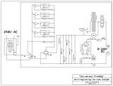
This information may be used entirely at your own risk.
There is always a way if there is no other way!
Hi Mik,
Just one point on your circuit diagram.
Following the input Isolating transformer, you will need a fuse of value 5 amps min (preferably 7 to 10 Amps).
I cannot read the V.A. rating of the transformer. It must have a secondary winding capable of the full circulating current of 4.56amps, that would require a V.A. rating of 1250VA.
It is the circulating currents that count, not the power output. With these high (4.56 amp) circulating currents, the transformer losses are equal to I x I x R (where R is the winding resistance) and the secondary wire is having to carry that circulating current of 4.56 amperes.
Nearly there:-)
The Laird
Thanks, TheLaird!
My 1:1 isolating transformer has only a 500VA rating. That is why I plan to put a 2A fuse in it. I actually need to read the brief manual for it again, there was something about that the thermal fuse inside the windings can blow due to a mild overload which will not blow the replaceable fuse of the transformer. I intend to put in a smaller replaceable fuse so that it will blow first!
Does this mean the circulating currents are flowing through the secondary windings of the isolating transformer even if there is no current taken out of the DC side of the charger (open circuit at full voltage)?
If that is the case, then I wonder why the transformer did not get hot at all, not even warm, during 26 hrs of continuous operation with 16+30microF MR caps and an output voltage of around 345V? The fuse did not blow, either!
I'll check again what fuses are in there and will measure AC current between transformer and charger with my clamp meter next time.
So far I was assuming that only the middle of the charging output curve would spell trouble for my undersized isolating transformer, because that's where the power is.
Yesterday I charged a Prius NHW10 half-pack of 120s NiMH cells with the 16microF MR Cap for about 12 hrs, at about 0.6A @ 172V; the transformer got only a few degrees warmer than ambient temperature.
EDIT: I had a look inside the transformer: It has a 5A fuse, which I have now replaced with a 2A fuse.
The manual warns against exeeding the maximum current rating, but does of course not tell you what that is! But on a label on the toroid I found the specs for the secondary winding: 2.1A . The thermal fuse is a 128degC fuse, not accessible.
The warning in the manual: "An overload condition is when current drawn by the appliance is above the transformers rated current but slightly less than the external fuse rating. Under this condition the transformer will keep operating until the thermal fuse blows due to overheating caused by the overload condition."
Slightly less in their world means 2.38 times overload! And, of course, it voids the warranty! That's why I've now replaced the fuse with a 2A fuse.
But as I said, the transformer did not heat up significantly and I checked it often!
This information may be used entirely at your own risk.
There is always a way if there is no other way!
Hi Mik,
You are right up to a point.
The maximum circulating currents would actually occur when the output voltage is lowest i.e. a short circuit or a very low voltage output. In this condition the power factor would be very low and the circulating currents very high. (4.6 amperes Max)
At maximum voltage (and zero current) output there would be no currents circulating in the capacitor or transformer secondary. The simple rule is "the current is the same in all parts of a series circuit" and here the transformer capacitor and load form a series circuit.
At about half maximum output voltage (using 240 volts as supply voltage and 340 volts as max output)) the power factor would be around 0.76 giving a phase shift of some 40 degrees (current leading). Impedance of the circuit would be 105 ohms. Real power input would be 390 Watts and output to the load (battery) 390 watts. The value of the 'leading' current, at the capacitor and transformer, would be 2.3 amperes from which the apparent power (the VA) would be 552 watts (the difference between the apparent power of 552 watts and the REAL power of 390 watts is accounted for by the power factor and Phase difference. (You really are testing/de-rusting my knowledge:-))
On balance, the simple way of looking at it is, that the current output is equal to the circulating currents at the transformer and capacitor, with the capacitive phase shift 'losing' the un-required voltage difference between the input (mains) and output(charge current).
The transformer is inductive and will generate heat according to it's IxIxR losses.
Incidentally, you pay only for the power you use (in this part of the world anyway), that is, as in real watts not as in volt amps. Industry is penalised if a reasonable power factor is not maintained but domestic use is not. Some fluorescent strip lights are power factor corrected, those for domestic use are often NOT P.F. corrected.
Learning all the time:-)
The Laird.
Hello The Laird, I understand that the "Universal Freddy" is very interesting, but can you answer this question (bellow) related to your initial post? Thank you very much.
Hi Jmap,
The answer to your question is that any charging current that creates /generates heat withing the cells is first of all wasted. It is, after all, supposed to be for the purpose of charging the battery and NOT for heating it up, and in generating heat, it is also doing damage. The heat causes expansion and pressures within the cells and also temperature differences within the cell. It is obviously hotter in the centre of the cell than at the outer cell case, this cannot be doing any good.
I view all unnecessary heat as a potential problem and excessive temperature as a source of almost certain damage.
It is my understanding that the Vectrix charger is doing damage whenever it is allowed to charge the battery past the 80% full point (which occurs at about 146 volts (varies a little with temperature) Certainly the Vectrix 3 amp equalising charge is excessive and even the 3 amp 'finishing charge' is causing trouble,
Incidentally, I have just had my bike on charge for two hours (starting with an empty battery). My garage was at a temperature of 8 degrees C. The battery starting temperature was 11 degrees C. After two hours, the battery voltage had reached 150 volts and was showing a temperature of 14 degrees C. (I didn't do this on purpose. For some reason the voltage display had 'locked' on 144 volts and the temperature display had also 'locked' at 11 degrees C. It was the charge current at less than 10 amps that alerted me to the 'lockup' problem) and my computer display which confirmed it.
I shut down the charge and checked the battery temperature two hours later. The battery temperature had gone up to 19 degrees C. After another three hours, the battery temperature was up to 22 degrees C.
I conclude that the cell internal temperatures were considerably higher than the 14 degrees C which showed at the end of charge. I have decided to restrict the charge time in future so as to allow the Vectrix's own charger to bring the battery only up to 146 Volts, which should represent about 80% of full, and then allow it to cool and finish off the charge with the 'Universal Freddy'.
I will log the results of this technique and post them when available. It may be a while, temperature here is less than 6 degrees C most days and I am getting soft with old age.
I appreciate that some heating of the battery in very low ambient temperatures may well be beneficial, but when the cell internal temperatures are high compared to the cells external temperatures then, I think, the cells are in trouble. When the cell temperatures are even throughout the battery and within the manufacturers 'limits', then you can expect a long battery life
The Laird
Thanks The Laird for your complete and fast answer. It's seems that it is worse than I thought... If the ideal charge is between 40% and 80%, then let us with 40% of the usual autonomy, that means about 30km to keep batteries in good shape. In other way I've experienced other kind of problems without doing equalization, it has some dangerous aspects also...
I will try to rethink my daily commute. Thanks.
I'm glad I'm not the only one. I've mentioned this before, but no one took notice.
Since I first observed it, I always time my charges so that when I come to the garage in the morning, before I go to work, my charge is at 14 bars (145V) complete.
Gone full circle.... and the recommendation in my first ever post about the Vectrix still stands. Use a timer! It's good for many reasons!
http://visforvoltage.org/forum/2547-vectrix-reports#comment-12252
This information may be used entirely at your own risk.
There is always a way if there is no other way!
You mean that the system gets frozen during charging?? that's pretty dangerous! If it keeps on charging it at 7 Ah 220v it would kill the battery, and maybe burn the bike.... What firmware do you have installed?
It's 7A, not Ah.
This information may be used entirely at your own risk.
There is always a way if there is no other way!
Latest firmware. Sometimes the Voltage and Battery Temperature readout freeze at certain voltage and temperature and even though the speed needle goes towards 10Amps, the voltage reads 144V, which is impossible, because at 100km/h=10A charging, the voltage should be 150V.
In that case, I discontinued charging and turned on the bike and I got 145V and 3°C higher temperature than what was the last value in the charging process.
This freeze has never happened with the old - pre October 2008 firmware.
Here's a link to a very useful pdf file from energizer concerning NIMH batteries. Lots of interesting information and many useful graphs.
http://data.energizer.com/PDFs/nickelmetalhydride_appman.pdf
As we are heading into winter and as we are discussing the effect of charging on battery temperature I was particularly struck by the following statement on page 24:
"Charge rates must also be reduced at low temperatures. An upper limit of 0.1C is
recommended below 15°C. Charging below 0°C is not advisable"
This article also graphs the self discharge of the battery as a function of temperature. Even without a load it is in the neughborhood of 10% within just a day or two, 20% after a week and as much as 50% after a couple of weeks depedening on the temperature.
They do recommend a trickle charge at C/40 (which would equal about 0.7A for the Vectrix) to keep the battry full.
That was of course meant to read: I'd use 1000V / 6A rated!
This information may be used entirely at your own risk.
There is always a way if there is no other way!
hello all !!!
I do have a problem to charging my vectrix scooter.I didn't have time to charge the scooter for last 6 months ,I had the scooter to my friend garage and now when i try to charge the scooter is totaly dead.I plug the power cord and nothing happend all my disply are without any power.I can hear some click noice when i plug the cord ,..but nothing else.
Somebody told me i need to reset the scooter but i don't know how and what i need to do.I think i dont have enough voltage (is zero now) to start charger.
My vectrix is 2007 v1 and I have less than 400 miles on it.
Any help will be glad apreciated.
Andy
Your voltage has dropped well below 100V. If you are handy , get a regulated 150V DC power supply, almost any amperage will do. Open the scooter and connect the charger to the battery. Charge until voltage is at above 100V. Disconnect and plug in the onboard charger.
Or even better, if you have a Vectrix dealer nearby, let him do this tech work. I'm sure at least 90% of us don't know and don't dare to do it by ourselves.
I differ with HarryS that after you charged up the battery to 100 volts you'd let the Vectrix charger finish the charging.
This thread it is about the problem and solution of the Vectrix charger overcharging the highest voltage cells when the cells are unbalanced which they would certainly be in your case.
What I would do is pull the Anderson connectors apart as soon as possible to stop the battery from further discharging, build the equalizing charger as described in this thread to charge the battery assuming it can over time be fully recharged this way.
Most important is to use the equalizing charger for the finishing charge to equalize all the cells or when the voltage gets to about 148 volts it will be finished charging.
We'll my power supply is 150V 0-3A. You could simply set it to 3A and let it go for 15h. When the battrey is empty you can charge an MIMH battrey at 1/10 C i.e. 3A for 15h to go from empty to full. I permanently installed wires with diodes and an Anderson connector. This way I can inject a top off charge or equalization charge as needed.
It's my understanding that the equalizing charger only starts being beneficial when the cell or cells with the highest voltage reach there maximum voltage that they can charge to at the .3 amp charging rate then the other cells start catching up until eventually all cells have the same voltage. So cell equalizing is only done at the very end of the charge unless the cells are very unbalanced.
If you charged at 3 amps for 15 hours using you 150 volt power supply and didn't overcharge any cells that would be alright or charged with the Vectrix charger and didn't overcharge any cells that would also be alright, temporarily disregarding the temperature factor.
One thing is the vectrix charger automatically shuts off when the battery reaches a certain voltage, if your timing was off with your 150 volt power supply you would over charge your battery at a 3 amp charging rate which is 10 times over the safe rate to equalize charge.
That is incorrect. 3A is a safe charge rate, if it is done with sufficient cooling. But you might not want to do this on a regular basis.
I got an oscilloscope now, unfortunately it's already broken before I could run the first real test. But I'll get a working one soon and then I can figure out how much ripple "Freddy" is producing under what exact circumstances. I had some unexpected capacity reductions in NHW10 half-pack cells after 5 charges with Freddy, that's why I want to test before routinely inflicting it on the Vectux.
Here is what a 3A charge (from very empty: 0.5A to 0.5V cutoff empty!) does to a single, clamped Vectrix cell up to 45Ah:
Much better picture here: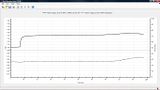
I have repeated this multiple times with different cells, it's typical behaviour.
This particular cell produced 34.79Ah at 20A to 0.9V cutoff immediately after this charge log was finished!
Nice! I think that is better capacity than any of the original cells out of the Vectux, but I have not tested them quite so rigorously.
And this cell is out of AZVectrix pack, in which all the celsidots have gone black due to overheating! One day we might find out how so much junk batteries ended up being sold in Australia.
Thanks to AZVectrix' generosity I can now test Vectrix cells under different charge scenarios. So far I found out that a 0.3A charge does get them almost full, with a terminal temp rise of 1.7degC only! But it takes a very long time, much longer than 0.3A * 100hrs = 30Ahrs.
Now testing at 0.6A, and waiting to hear about the broken oscilloscope....
This information may be used entirely at your own risk.
There is always a way if there is no other way!
A few comments on NiMH charging, supplementary to the Laird's fairly comprehensive original post.
The reason that some sources recommend against low-rate charging of NiMHs, is that when you do this it prevents automatic end-of-charge detection systems from working reliably, and most modern chargers use the technique of dV/dT (rate of voltage change) supplemented by over-temp cutoff to determine end-of-charge. Such systems work well for relatively small chains ofc cells (1-12), but as the cell chain gets longer this technique becomes less reliable, due to the cells slightly different states-of-charge masking the voltage peak that is being looked for, when summed. With indivdual cell monitoring, or monitoring in strings of a few cell, this charge-state-determination method can still work fine. Does the vectrix have individual cell monitoring or not?
On Cell temperature, this page gives a useful overview of how temperature affects cells: http://www.mpoweruk.com/life.htm
Essentially all chemistry happens faster at higher temperatures, normally twice as fast per 10C temp rise. That means improved output at higher temps, but also faster unwanted reactions which can reduce cell life. It seems that any temp over 30C will have a significant effect on overall NiMh life, which is why the GP datasheets all specify storage below 35C, even for their high-temperature cells. So whilst there probably is no absolute limit, keeping charge temp below 35C seems like a good target. The datasheets all specify maximum charge temperature as 40C or 50C for nomal cells, and 70C for high-temp cells. Fast-charging minimum temp is 10C (because the chemistry can't keep up below that temp). 'fast charge' on the Vectrix cells is 30A. I assume the charger is rather less manly than that, so the actual limit will be somewhere in the 0-10C range. Of course if you have very low ambient temps and you need to charge the pack there is not much you can do except allow self-heating to get you into the 'OK' range. Starting the charge off slowly is probably the best tactic in this situation. The enthusiastic could use a local electric heater first, although I'm not sure how good an idea that really is.
It is a useful feature of NiCd and NiMH technologies that they can take a certain (small) amount of overcharge current without damage, which makes series-charging of cells practical as it helps remove cell imbalances in a pack. The chemistry of absorbing the overcharge does generate quite a lot of heat and potentially some gas, so it should be done carefully and for a limited time at limited current. I am not sure how the details of this change vary (if at all) from conventional cyclindrical cells to the large prismatic cells used automtive applications. Consumer cyclindical cells are deliberately designed to take a bit of over-charging abuse. I don't know if that is true of the 10GP30EVH cells used in the vectrix. I have been unable to download the datasheet for these cells, as the only link I have is duff and the evbtech site uses flash in a way that doesn't work at all on my browser.
It does seem that what is needed is a proper BMS to manage each cell individually to prevent excessive discharge, and to ensure that balancing/equalisation occurs near full charge, as is normal practice with lithium cells. The problem with lithium BMS systems is that they will fail to spot the 'full' status of NiMH cells because the voltage does not rise continuously until the cells have been overcharged for quite a while. One of the forthcoming generation of microcontroller-based designs with both tmep and voltage monitoring of each cell would be ideal, but no-one has yet made one of those which is both debugged and widely available.
It would be smart if some of the people interested in NiMH monitoring chipped in on the various endless-sphere BMS threads to argue for the features needed for NiMH management as well as Lithium.
Wookey
Sakura s50 (Efun A)
Pages