I am using a "Universal Freddy" which is very close to the schematic below, except that I have replaced the 20microF capacitor with a 16microF capacitor.
The current shunt for the ammeter does not work quite as expected (those resistors are too inaccurate) but is useful nevertheless. It gives about a 1:3 reduction.
The large motor-run capacitors (16microF and 30microF and their sums) should probably only be used when charging batteries close to 340V, to keep the charge current reasonably high; that means, they are not needed for charging a Vectrix battery at low current.
Smoothing resistor/s need to be introduced into this design - at least that's what I think the test result on ES mean! Even at about 0.6A, there seems to be so much ripple that the cells are being discharged a little bit every 1/100th of a second!
0.3A (8microF) might just work without smoothing resistor, but note that this Freddy has double as much smoothing capacitance as the original design!
I think the original design does need the resistor.
This information may be used entirely at your own risk.
I've been running my bike down to 1/2 on the gauge and letting it sit 24hr's before recharge to cool and self discharge the high cells. After a couple of weeks of that, I deep discharged the pack to battery light and recharged. Finished EC at 25 deg, starting temp 17
I just ran it at 80km/h average for 45km before it started limiting the power.
seems like a good method to maintain battery balance without cracking open the battery box.
Thanks Matt for pointing out the change in self discharge rates at different SOC.
I opened up "Universal Freddy" and was reminded of my rule Nr.1 for prototyping electronic gizmos: Use a bigger box!
There is just not enough space to comfortably try out different versions of ripple reduction resistors.
So I will try to make a second box, external to Freddy, and call it the "Ripple Buster":
I have a "hunch" that it will work better to have multiple steps in a ladder than just on big step; but the maths needed to calculate this are beyond me for now - the time I would be willing to invest to learn it etc...
Here is my rationale for using this setup (which might be faulty as all buggery, please flame away!):
- I can plug this "Ripple Buster" between many different cheap chargers, and many different batteries.
- I do not need to spend several days to re-build "Freddy" before I can use it again. This Ripple Buster is relatively easy to build (if the box is big enough...)
- the 1 Ohm (10W) resistors can cope with 3Ax3A x1Ohm = 9 Watt (I^2 x R). That is enough to "fast-EQ charge" a Vetrix NiMH battery, and enough to fill a Prius MK1 battery in 2 hours, provided I find a (ripply) DC power source of sufficient specs. But it is too close to the maximum specs for my liking.
- at 2A x 2A x 1 Ohm = 4W it can EQ charge a Vectrix reasonably fast, and fill a Prius MK1 battery in three hours. That'll do, it will be a really useful engine! (says the fat controller)
- being a separate device from Freddy, I could use an isolating transformer, Variac and bridge rectifier to feed into it (instead of Freddy).
- as a separate device in it's own large box, I can change parts much more easily in case the design needs some change. I'll learn a lot about Ohm's law (and it's lesser known relatives), smoothing and oscilloscopes!
Let me know what you think about this, please.
Of particular interest to me would be answers to this question: Would a single 14ohm resistor work just as well as the 7 separate 1ohm resistors?
Please let me know.
This information may be used entirely at your own risk.
When attempting to cut ripple down,a inductor is more effective , with removing the AC component of the waveform with less DC loss .
down side is cost and size .
Resistor will help but at great power loss ( heat )
Try finding a inductor/transformer with very low dc resistance , what inductor you use the inductance will reduce the ripple .
HEAT & LOSS & INEFFICIENCY RELATED DIRECTLY to IMPEDANCE
I had a brief look into the inductance ripple reduction, but it's too complex for me, for now.
The components for the Ripple Buster resistor-capacitor ladder are readily available, and the power losses are not that significant because I do not want to use this charger as a regular, every-day-charger. It is a tool to service batteries with an EQ charge every now and then; and to re-awaken long neglected batteries.
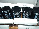
So I built this today:
Ready to roll for experimenting tomorrow!
The resistors are screwed in and can be exchanged for other resistors, or shunts, if I want to experiment with different resistor values or patterns.
One question I find particularly interesting is this one: Will it make a difference if I switch the input and output for either positive or negative side of the paralleled capacitors? Is there an electric equivalent to the "Gegenstromprinzip" used for making heat exchange (or gas exchange et al) more efficient? http://de.wikipedia.org/wiki/Gegenstromprinziphttp://en.wikipedia.org/wiki/Countercurrent_exchange
Maybe I should add in some fuses into the Ripple Buster, just in case, before I try it out....
This information may be used entirely at your own risk.
Mik
Here some thoughts when working with higher voltage pack ,not to worry when dealing with 24 -48 volt
Your ripple reducing box with capacitor will act as a dead short until charged, essentially what you have is 14 1 ohm resistor in parallel or roughly 66 milliohm shunt across either side ( charger or batteries ) until all the caps are charge up .
Make sure that what ever supply you connect up is current limited ( your charger is since it use cap in series, the battery side will only be limited by its internal impedance, I would connect the charger side first then the batteries to lessen the inrush current ( or spark).
If you connect the battery side first then you will have a very large current charging up all the cap .
For example if you have 200 volt batteries and you hook it up first , the initial charging current for a instant could be as high as 2880 amps (doing simple math, it will depend on the battery SOC and internal impedance, but still a nice healthy spark ,if you use a switch it may weld .
With applying the charger first, the current is limited by the series cap and the isolation transformer, there will be a spark since you have cap across the bridge that may be charged , applying the AC power after making the ripple box connection , then connect the battery.
If you where using a inductor instead of resistor, the charging current will be limited by the inductance.
HEAT & LOSS & INEFFICIENCY RELATED DIRECTLY to IMPEDANCE
The ripple buster is interesting. But is it really necessary?
If you consider that the ripple output of Freddy is a relatively small voltage compared to the charging voltage of the Vectrix (140volts) even as a percentage it is quite small, it shouldn't produce any detrimental effects.
Have you got a true measurement of the ripple voltage and the ripple current? How did you measure them and what are these measurements?
I haven't yet done any measurements but will try to collect some info in the next week or so.
The circuit you have drawn for your ripple reduction has some fundamental mistakes. There is no need to put resistors in both positive and negative lines, use the positive or negative line only. The reactance of the capacitors will provide a ratio of ripple reduction in conjunction with the value of the resistors. Bigger resistors will provide greater ripple reduction BUT they also generate more heat.
The suggestion of an inductor and capacitors is a better solution. Larger inductance equates to less ripple.
Let me have some figures for the charging voltage and current ripples (must be measured whilst charging the Vectrix battery) and I will endeavour to investigate any problems and produce a more practical answer to your concerns.
The ripple buster is interesting. But is it really necessary?
If you consider that the ripple output of Freddy is a relatively small voltage compared to the charging voltage of the Vectrix (140volts) even as a percentage it is quite small, it shouldn't produce any detrimental effects.
Have you got a true measurement of the ripple voltage and the ripple current? How did you measure them and what are these measurements?
I got a USB scope now, and it works somewhat. I cannot really tell if the thing is malfunctioning or not, but it sometimes seems to do strange stuff until the program gets rebooted and the hardware disconnected and reconnected.
And I cannot figure out how to calibrate it and set the zero point...
So all these results might be rubbish!
The thumbnails below lead to screenshots of the USB scope measuring the voltage drop across a 10mOhm shunt. The shunt is in series with the Freddy charger and the HP2 out of the BlueCar NHW10 battery (120s NiMH, 6 or 6.5Ah). Battery is empty, started at around 145V, at end of experimenting it was about 155V.
The title of the scope graphs can be seen below them once you have clicked on them, and they describe details about them: Charge current, motor run capacitor used to achieve this current, and either 12 Ohm resistor added in series or no resistor added. The resistor should probably be located between the smoothing capacitors, but for this experiment I simply put it in series with the charger output.
The actual zero line should be where 0.01V is; here is what the scope shows when no current is going through the shunt. It stubbornly claims -0.01V when it should be zero....
Any help with figuring out how to properly use this scope, and what the results mean (if anything), would be greatly appreciated!
If I interpret these graphs correctly, then the Freddy charger without resistor creates so much 100Hz ripple that the charge current becomes negative for a short time each 1/100th of a second.
With a 12 Ohm resistor, there is still a lot of ripple, but the current always goes into the cell, rather than reversing each hundredth of a second.
I have been using the 8microF / 0.64A setting to cycle the NHW10 HP1 5 times, without smoothing resistor.
Is that likely behind the 5% capacity reduction?
I haven't yet done any measurements but will try to collect some info in the next week or so.
The circuit you have drawn for your ripple reduction has some fundamental mistakes. There is no need to put resistors in both positive and negative lines, use the positive or negative line only. The reactance of the capacitors will provide a ratio of ripple reduction in conjunction with the value of the resistors. Bigger resistors will provide greater ripple reduction BUT they also generate more heat.
I think I causes no problem to add resistors to positive and negative lines, but it allows to have more surface area with better heat dissipation.
The suggestion of an inductor and capacitors is a better solution. Larger inductance equates to less ripple.
Let me have some figures for the charging voltage and current ripples (must be measured whilst charging the Vectrix battery) and I will endeavour to investigate any problems and produce a more practical answer to your concerns.
Keep smiling:-)
The Laird
I think I better continue to experiment with the NHW10 batteries on the bench. I have many of them, but only one Vectrix battery, and that one is in the bike.
What I learn from charging these 6Ah 120s NiMH batteries should be applicable to 102s NiMH Vectrix batteries, within limits of course.
Thank you for your interest and help with this!
This information may be used entirely at your own risk.
I have measured the ripple on both voltage and current with Freddy in action on a virtually full Vectrix battery.
Voltage ripple measured across the charger out put terminals was 6.5 volts rms. This corresponds to 4.5% and is equal to 0.07volts ripple per 1.41 volt cell. This is not a figure that causes me any worry.
The Current ripple was greater at 0.09 amperes rms, representing a ripple of 30% on the charge current of 0.3 amperes. Again, I don't find this worrying and as far as I can establish there is little in any of the available specifications to indicate that ripple free charging is necessary, indeed, in some battery types ripple is beneficial.
Mik's graphs, in the main, show considerable high frequency pulses which cannot be the product of Freddy. It seems likely that the 'Scope being used is generating these h.f. signals. The output of Freddy is a series of positive half cycles of sign wave shape smoothed out by the capacitors (which follow the bridge rectifier) and also by the battery being charged. These half cycles are of 10mSec duration (each). There will be a very short duration of zero volts between consecutive half cycles due to one set of the bridge diodes switching off and the other pair of diodes switching on (this occurs for about 1.2 volts of the 680volt peak to peak input cycle and lasts for about a microsecond) you would be hard pressed to see this on a 'scope in the normal course of observations.
The comment of a 'reversal' of the charging current being 'removed' by the addition of a resistor is again likely to be an error in observation. The diode through which the current passes to reach the Vectrix battery would preclude any possible current reversal.
I am still doubtful of the need for 'ripple reduction'. However, if ripple must be removed, the better way by far to remove ripple is to use an inductor in series with the current and a capacitor across the output. An inductor of 0.1 Henrys and a Capacitor of 100 microfarads would give a ripple reduction of 4:1 with a volt drop of about 19.2 volts and no power loss (based on the original Freddy circuit). The use of a resistor is basically a 'loser' because of it's heat production / dissipation and power loss. To achieve the same result with a resistor (64 ohms) there would be a power loss of 5.7 watts
Bye the way, Looking at the circuit of 14 x 1 Ohm resistors and 8 x 100 Microfarad capacitors, this will give a ripple reduction of only 2:1 i.e. it will reduce the ripple to one half of the input ripple.
There is little more to be said on this topic. I believe in keeping everything as simple as possible as you may have noticed, remember the old saying "K.I.S.S. - Keep It Simple, Stupid".
I am willing to be corrected and will respond to any points which anyone wishes to raise, and NO I am not suggesting that anyone is stupid.
I have measured the ripple on both voltage and current with Freddy in action on a virtually full Vectrix battery.
Voltage ripple measured across the charger out put terminals was 6.5 volts rms. This corresponds to 4.5% and is equal to 0.07volts ripple per 1.41 volt cell. This is not a figure that causes me any worry.
The Current ripple was greater at 0.09 amperes rms, representing a ripple of 30% on the charge current of 0.3 amperes. Again, I don't find this worrying and as far as I can establish there is little in any of the available specifications to indicate that ripple free charging is necessary, indeed, in some battery types ripple is beneficial.
And how did you measure this? (I'm not doubting your results, just want to learn how to do it properly!)
Mik's graphs, in the main, show considerable high frequency pulses which cannot be the product of Freddy. It seems likely that the 'Scope being used is generating these h.f. signals. The output of Freddy is a series of positive half cycles of sign wave shape smoothed out by the capacitors (which follow the bridge rectifier) and also by the battery being charged. These half cycles are of 10mSec duration (each). There will be a very short duration of zero volts between consecutive half cycles due to one set of the bridge diodes switching off and the other pair of diodes switching on (this occurs for about 1.2 volts of the 680volt peak to peak input cycle and lasts for about a microsecond) you would be hard pressed to see this on a 'scope in the normal course of observations.
It's my first attempt at using a scope for anything (other than a few minutes in long ago school classes) and I am trying to work out what is malfunction/noise/operator error and what not. The higher frequencies in there, I thought, were due to the measurements being done at the highest sensitivity setting of the scope. I'm trying to measure mV across a 10mOhm shunt. Could the raggedness of the graph have something to do with the "floating" nature of the Freddy output? The scope is not grounded, I am running it through a galvanically isolated USB hub to avoid frying my laptop (again).
But despite higher frequency ripple of less than 5mV distorting it a bit, the 100Hz ripple from Freddy is the dominating curve in there.
Below is the measurement with the most similar settings to the original Freddy with 8uF motor-run capacitor but NO smoothing resistor. But this Freddy has 4 x 100uF smoothing capacitors (instead of 2) and charges a 120s NiMH battery (instead of the Vectrix' 102s NiMH battery):
The comment of a 'reversal' of the charging current being 'removed' by the addition of a resistor is again likely to be an error in observation. The diode through which the current passes to reach the Vectrix battery would preclude any possible current reversal.
I agree, and gladly! The only way that some reverse current could flow through my particular Freddy is through the volt meter circuit. It does not have a blocking diode between battery and voltmeter, like in your original design. (But on the Vectux I do have a blocking diode close to the battery in the Freddy charging connection.)
But even if a small reverse current through the voltmeter is possible, it would be totally impossible to spot it on the scope as a voltage across the 10mOhm shunt! It would be in the order of 0.0008A, causing a voltage of (0.0008A x 0.01 Ohm = 0.000008V = 8uV) across the shunt! Three orders of magnitude to small to see! Therefore, the bottom end of the 100Hz ripple must be a measurement error.
Here is a diagram of the complete measurement circuit used:
I think this error is actually due to a lower frequency ripple going through the measurement! This ripple has about 13Hz frequency and is obvious in the 1.86A @ 46uF measurement:
I am still doubtful of the need for 'ripple reduction'.
I am by no means certain about this either! Ripple, as long as it always results in a positive current flow into the battery, could even ensure that parts of the cell with higher IR get charge when very low charge currents are being used, like here at 0.3A = C/100 for the Vectrix!
But my reason for trying to get to the bottom of the "ripple question" was the unexplained 5% capacity loss of a NHW10 120s NiMH battery after 5 cycles done with Freddy. Better safe than sorry!
Compare the below discharge curves at 12A from full charge. The 1V cutoff curves resulted after one charge with Freddy, the 0.9V cutoff curves after 5 or 6 charges with Freddy: Would that make you worry about your batteries?
The capacity loss of these cells has probably nothing to do with Freddy, but it is the first reason that must be ruled out in order to "Primum, non nocere"! (First, do no harm!)
The NHW10 cells were possibly just bouncing back from the "mother of all reconditioning discharges": A very slow self-discharge to almost zero volt! (That might of course be total nonsense.....like my idea to use the counter-current principle with a resistor-capacitor ladder.)
These batteries had been left uncharged for years, the 120s string had about 11V total before I got to work on it! One of the 6-cell sticks had 11mV only. Hence the titles for the posts on ES: "Is this battery dead as a Dodo, or a Phoenix?" and "A Phoenix or a Dying Swan?"!!!
I really don't know, but I do not want to test it by doing multiple charge cycles on the only Vectrix battery I have!
However, if ripple must be removed, the better way by far to remove ripple is to use an inductor in series with the current and a capacitor across the output. An inductor of 0.1 Henrys and a Capacitor of 100 microfarads would give a ripple reduction of 4:1 with a volt drop of about 19.2 volts and no power loss (based on the original Freddy circuit). The use of a resistor is basically a 'loser' because of it's heat production / dissipation and power loss. To achieve the same result with a resistor (64 ohms) there would be a power loss of 5.7 watts
Bye the way, Looking at the circuit of 14 x 1 Ohm resistors and 8 x 100 Microfarad capacitors, this will give a ripple reduction of only 2:1 i.e. it will reduce the ripple to one half of the input ripple.
I don't know how to calculate the ripple reduction, but the test results shown at http://visforvoltage.org/forum/8426-taking-universal-freddy-limit look to me like a much, much better than 1:2 ripple reduction with the "Ripple Buster"! But those tests were done with the Freddy output (practically) shorted through the 10mOhm shunt and might not be applicable to a situation with a battery instead of the shunt.
Like this:
Here are some reduced size pictures to show what I mean. The full size pictures are in the new thread linked above.
The first graph shows the "ripple" at zero amps. It shows the "noise" only, whatever is creating it.
The second graph shows the maximum current my Freddy can do for a short time without blowing it's fuse: 2.89A with 46UF motor-run capacitors, but with the ripple buster in series.
The third graph shows the ripple at 3.16A (46uF) without the ripple buster:
That looks to me like almost complete ripple absence, rather than 1:2 reduction.
As I said, maybe it's all different with a battery connected. Or maybe this the answer to my question from a few days ago: "Would a single 14ohm resistor work just as well as the 14 separate 1Ohm resistors? (The original question had a typo in it, 7 instead of 14). And, quoting myself again: "I have a "hunch" that it will work better to have multiple steps in a ladder than just on big step".
If your calculation of 1:2 ripple reduction is correct for a 14Ohm resistor, then maybe my "hunch" was right and the ladder is much superior with many small steps compare to one big one?
However, tests with battery shall follow, and with my increasing knowledge of how to use a scope, the results should become more meaningful and reliable.
About the power loss due to the resistors: At 0.3A charge current you get 1.26W power dissipation through the 14 x 1R resistors; while 43W are going into the battery at 143V. That is a 2.9% loss. At higher currents the ratio gets worse, because of the exponential nature of power loss through a resistor (I^2 *R = W) and the linear increase of power to charge the battery (V * A = W).
There is little more to be said on this topic. I believe in keeping everything as simple as possible as you may have noticed, remember the old saying "K.I.S.S. - Keep It Simple, Stupid".
I am willing to be corrected and will respond to any points which anyone wishes to raise, and NO I am not suggesting that anyone is stupid.
Keep smiling :-)
The Laird
No worries, I don't take it that way at all and am grateful for your answers!
I like to keep it simple, too! And the maths and theory are too complicated for me right now, so the seemingly complicated experiments are the way to keep it simple for me. Not that it's all that simple to figure out how to use a USB oscilloscope on devices that can produce hundreds of amps at hundreds of volts....
But it seems so much simpler than trying to figure it out theoretically!
This information may be used entirely at your own risk.
First Point. Freddy is as original circuit, that is WITH the resistor. (Not that it will make much difference).
The Voltage Ripple measurement is relatively easy. An A.C. ammeter is used with a series capacitor across the power line to the battery. The diagram below shows the method. Meter B and C1.
How it works. The series capacitor blocks the D.C (all 144 volts of it) But allows the A.C. (the ripple) to pass to the meter. The meter range is scaled down (always start with a high setting) until a reading is obtained. This reading is the R.M.S value of the ripple and is adequate for this type of ripple.
Warning Following this measurement the capacitor will have a charge on it of 144volts. Short circuit the terminals of the capacitor before handling it or expect to become very shocked when you touch it.
The Current Ripple measurement Using meter A. Is straightforward the ten Ohm resistor will show a voltage across it's terminals which is related directly to the current passing through it. From Ohms law we can calculate the ripple current which is equal to the A.C. voltage measured divided by the resistor value in ohms. In my case I measured 0.9 volts across the ten ohm resistor which gives 0.9/10 =0.09amperes (R.M.S. because the meter gives R.M.S. values for A.C. - peak values are usually obtained using an oscilloscope).
Ripple Reduction Filters (Low Pass Filters in electronics terms).
These devices simply reduce the ripple according to ohms law / potential divider principles.
A simple filter is shown below.
In this filter I have shown an inductor OR a resistor in series with the output and a capacitor across the output. The ripple reduction is equal to the ratio of the reactances of R:C or L:C whichever is being used.
The reactance of the inductor is given by XL=2πfL. Where Xl is the inductice reactance in ohms
Pi =3.142 and f= frequency in hertz.
The reactance of the capacitor is given by XC= 1 Divided by 2πfC. Where Xc is the capacitve reactance in ohms. Pi = 3.142 and f = frequency in hertz.
Reactances are all measured in ohms and can be used directly in ohms law calculations.
In the circuit above, if R=64 ohms and C= 100 microfarads then the ripple reduction is 64:16 or 4:1
if L=0.1Henrys and C= 100 microfarads then the ripple reduction ratio is 64:16 or 4:1
Enough of this 'teach in'.
Mik's graphs show a ten hertz hum signal superimposed on the waveforms. The waveforms are obviously digitised but with no indication as to the scale (left vertical) it is hard to decipher. I can be fairly certain that what is shown is NOT the output of Freddy, The wave shapes are not what would be obtained from a charger output of this type. A typical charger wave shape is shown below (for a simple (Freddy type) charger).
The D.C. offset is taken care of by a x10 Probe on the 'scope input.
Will leave it there for now. I hope that I have addressed most questions. Comments and requests for more information is welcomed.
First Point. Freddy is as original circuit, that is WITH the resistor. (Not that it will make much difference).
I think it does make a difference! Heisenberg sends friendly greetings....
You have made the measurement with the 10 Ohm and an additional 10 Ohm resistor in the circuit, i.e. 20 Ohm. Therefore it makes perfect sense if you find that there is less ripple in the system than when I test with no resistor or a 12 Ohm resistor in series! I used a 10mOhm shunt; you used a 1000 times bigger shunt, plus the already 1000 times bigger resistor in the original Freddy. That's why you get different results.
The Voltage Ripple measurement is relatively easy. An A.C. ammeter is used with a series capacitor across the power line to the battery. The diagram below shows the method. Meter B and C1.
The diagram is a bit small, but it looks like you put an AC voltmeter as Meter B in the diagram. Is it a voltmeter or an ammeter? Analog or digital TRMS?
How it works. The series capacitor blocks the D.C (all 144 volts of it) But allows the A.C. (the ripple) to pass to the meter. The meter range is scaled down (always start with a high setting) until a reading is obtained. This reading is the R.M.S value of the ripple and is adequate for this type of ripple.
Warning Following this measurement the capacitor will have a charge on it of 144volts. Short circuit the terminals of the capacitor before handling it or expect to become very shocked when you touch it.
The Current Ripple measurement Using meter A. Is straightforward the ten Ohm resistor will show a voltage across it's terminals which is related directly to the current passing through it. From Ohms law we can calculate the ripple current which is equal to the A.C. voltage measured divided by the resistor value in ohms. In my case I measured 0.9 volts across the ten ohm resistor which gives 0.9/10 =0.09amperes (R.M.S. because the meter gives R.M.S. values for A.C. - peak values are usually obtained using an oscilloscope).
As I said above, I think your measurement method very significantly changes the resulting ripple!
Here are two oscilloscope measurements during charging a 120s NiMH battery with Freddy. Both measure voltage across a 10mOhm shunt in series with the Freddy output. The first is without smoothing resistor, the second with a 12 Ohm resistor between Freddy and the battery, just where you put the 10 Ohm resistor for your measurement.
There is a very clear difference!
The Y achsis is in Volts, sorry I did not notice earlier that this is not shown in the display captures. It is beyond me why the USB scope software does not capture all the settings along with the measurement curves!
...
...
Mik's graphs show a ten hertz hum signal superimposed on the waveforms. The waveforms are obviously digitised but with no indication as to the scale (left vertical) it is hard to decipher. I can be fairly certain that what is shown is NOT the output of Freddy, The wave shapes are not what would be obtained from a charger output of this type. A typical charger wave shape is shown below (for a simple (Freddy type) charger).
As above, the Y achsis is in Volts. Sorry about the missing label, I did not notice it! I think the waveform is insufficiently detailed because the voltage differences are so close to the maximum voltage resolution of the scope. It cannot show such fine details at such low voltage levels. A 0.3A current across the shunt only results in 3mV deflection on the Y-achsis.
The D.C. offset is taken care of by a x10 Probe on the 'scope input.
If I use the x10 probe setting, then I cannot measure the small signal across the 10mOhm shunt at all.
Will leave it there for now. I hope that I have addressed most questions. Comments and requests for more information is welcomed.
The Laird
[/quote]
I'll try to measure with a different X-achsis resolution to show that it is the correct waveform. But I know already that it is the Freddy output, because it happens to appear and disappear on the scope output screen just at the right times, every time; and never when Freddy is not putting current through the shunt!
Thanks for the explanations. I hope I'm not getting too annoying here, but the measurements seem to contradict the predictions at the moment....
It might all be due to my operator error and inexperience with the oscilloscope, but for now I think my measurements are relatively accurate.
That does not mean that the ripple does damage - so far I can only measure the ripple, but not it's effect on batteries.
This information may be used entirely at your own risk.
The issue here is a/ whether the ripple on Freddy is causing a problem as in loss of capacity. and b/ how much ripple is Freddy putting out?
With regard to issue a/, The battery in question appears, by Mik's report, to be losing capacity following five charge / discharge cycles. There are limited possibilities here and they are.
1. The battery in question is causing the problem.
2. Freddy is causing the trouble in some way or other.
As Mik has possesion of the battery and Freddy I can only speculate on the cause of the problem, however, Mik has said that the battery was in a very sorry state at the start of this process and from this starting point I will suggest that the battery has actually been improving over each charge / discharge cycle and that it's terminal voltage at full charge is rising with each charge. This could result in the battery requiring the charge to be continued until the higher terminal voltage is reached. Basically, the battery is not now receiving a full charge.
It is normal for battery terminal voltages to be higher when new and to lower with aging. If an 'old' battery is being resurrected then it is reasonable for this process to reverse to some extent.
I have never experienced a battery being damaged by charging except where the 'ripple' was actually caused by a fault and produced a massive short duration pulse of charge current at a relatively slow pace.
If the ripple output by Freddy is suspected of causing the problem then the sure way to prove it is to charge the battery by another means and check the result. This is sound engineering practice when there are too many unknowns to deal with easily.
Back to the ripple measuring
The ten ohm resistor shown in my measuring diagram cannot affect the shape or amplitude of the ripple, it is a passive component, it can only convert the current flowing through it into a voltage across it which is exactly what we need to measure the ripple current. To change the ripple shape you need more than a resistor. The value of the resistor is largely irrelevant as it has no effect on the wave shape. The bigger the resistor the greater the voltage developed across it and the easier to measure. Freddy can provide any 'lost' voltage again without changing the waveshape.
Both of the meters are voltmeters. It doesn't matter digital or analogue, we are only measuring the ripple content in terms of r.m.s. value. The shape is highly predictable from the circuitry and is of little relevance.
If Mik's statement on the voltage scale is correct then there is no problem. However, the wave shapes are not as expected (even if there were fault conditions present in the charger) and the amplitudes are far too small. I would expect to get a peak to peak ripple value which is larger than the r.m.s. figures.
To get acceptable size waveforms on a 'scope it should be a.c. coupled and the scale set to display the expected size of waveform. The times ten probe would only be used to measure the d.c. level of the waveform in a case like this.
The thinking is getting too involved for this relatively simple problem, keeping it all simple will help immensely.
If I understand what I read, this "scope" is a probe/USB input to a laptop with a "scope" program on it. My first thought when looking at the waveform was 60Hz hum as I have seen 1000 times when picking up the tip of my Tektronix probe. My second thought is the well documented problems with any USB input in an electrical noisy environment. Therefore without comparing the observed waveform to that on a scope with a shielded input, I would have a hard time putting forth any judgment on the Freddy other than to say ignore the hum. The battery is not being affected by it.
When a 100 microfarad capacitor was added to the ouput of Freddy, the ripple dropped from 4.0 volts to 3.5 volts peak to peak.
By calculation the current ripple is equal to V divided by R. = 4.0 divided by 10= 0.4amperes Pk to Pk equaling an r.m.s. value of 0.14 amperes R.M.S. ripple.
The current ripple of 0.14 Amperes on a current of 0.6 amperes equates to 23%ripple.
The voltage ripple is very low at only 10 millivolts pk to pk.
The above is all done with only eight cells. The current ripple, as a percentage, will be the same when charging the full battery of 102cells. The voltage ripple will also be the same on the full 102 cells
...
...
Mik has said that the battery was in a very sorry state at the start of this process and from this starting point I will suggest that the battery has actually been improving over each charge / discharge cycle and that it's terminal voltage at full charge is rising with each charge. This could result in the battery requiring the charge to be continued until the higher terminal voltage is reached. Basically, the battery is not now receiving a full charge.
Interesting idea!
I was expecting the battery to improve with each consecutive charge, with capacity at 12A to 0.9V cutoff being the measure of such improvement. But I got a capacity reduction.
I have just gone over my detailed records and I found the likely reason!
It was the "Increased self-discharge rate with higher temperatures trap"!! That one gets you every time you park your Vectrix in the sun, or do an EQ charge in hot weather. End the charge at 40degC or more, and the battery empties a significant amount of it's charge over the next few hours, due to heat related increased self-discharge rate.
In this case, the re-awakened NHW10 BlueCar HP1, the first full charge with Freddy ended with 40degC cells (or thereabouts). I let the battery rest and cool overnight, then gave it a 1hr top-up charge: Charging at 0.6A for 1 hr Nr. 13: 2010-01-15, 0558am: At end: 174.2Vmax; 174.0Vactual; 322.6Ohm; 32.8degC;
Nice and full it was, and only 32.8degC warm! Then I let it rest for about 9hrs and began the capacity testing.
Four Freddy charges followed, interspersed by discharging (through another gizmo I made from 240V light bulbs and a SMR from the Prius) without accurate capacity measurement.
Then came the recharge Nr. 5 and the following capacity tests on the 20 "sticks". And that's where the error occurred!
Having become more confident with the semi-automated charging through Freddy and a timer, I finished the charging process with a 1hr charge around midnight, unattended.
The records read: 2010-01-29, 2255pm: 1hr at 0.6A: 25.6degC; 321.5ohm; 160.2V at start.
0.63A at start. 2356pm: 171.6Vmax: 321.9ohm; 28.8degC restarted for further 1hr.
2010-01-29, 2358pm: 1hr at 0.6A: 0730am: 171.9Vmax: 327.0ohmmax; 322.1ohmactual; 162.1Vactual; 30.8degC now.
full
The 327.0 Ohm (automated peak recording) mean that the battery got to about 44degC, about an hour after the charge had finished at 0100am. Vmax had been 171.9V due to this higher temperature during charging, as opposed to the 174.2V during the first charge at 32.8degC.
The I started capacity tests about 9hrs after end of full charge, and got 5% lowered results.
Then I got worried and repeated the "charge to full whilst hot", and tested just 2 sticks. Again, the capacity was lower than the first time.
A 9hr rest period starting with 45degC causes easily 5% reduced SOC, when compared to a 9hr rest period starting with 33degC!
Mystery (part 1) solved!
It is normal for battery terminal voltages to be higher when new and to lower with aging. If an 'old' battery is being resurrected then it is reasonable for this process to reverse to some extent.
I have never experienced a battery being damaged by charging except where the 'ripple' was actually caused by a fault and produced a massive short duration pulse of charge current at a relatively slow pace.
If the ripple output by Freddy is suspected of causing the problem then the sure way to prove it is to charge the battery by another means and check the result. This is sound engineering practice when there are too many unknowns to deal with easily.
This way of checking it would only work if the capacity loss is temporary. Had I not committed the above mentioned blunder (rest period at different cell temperatures), then there should not be any capacity changes because I always used Freddy to charge these Prius NHW10 batteries. So the result should be the same each time, unless the capacity loss is irreversible.
The way to check will be to charge with Freddy, let cool, top-up for one hour, then rest and test. Like the first time. Or, I could just give up and assume the mystery is solved (which it most likely is)!
Back to the ripple measuring
The ten ohm resistor shown in my measuring diagram cannot affect the shape or amplitude of the ripple, it is a passive component, it can only convert the current flowing through it into a voltage across it which is exactly what we need to measure the ripple current.
I'll reply to that later - just noticed your next post with the scope photos and need to have a good look at it all.
Otherwise we will bog down this thread - certainly one of the best in the Collaborative Handbook - and make it hard to access. It happened to me before, open the following link with a slowish internet connection and you will see what I mean: http://visforvoltage.org/forum/3582-vectux-quotopen-source-vectrixquot
This information may be used entirely at your own risk.
I have several automatic NiMH chargers so I will put some batteries in them and look at the charging waveform. I expect to see all manner of tiny ripples in the output. I can not imagine this is of any concern to the life of the battteries.
I don't understand what you are saying as in one line you state the ripple voltage as 4V p-p and then 3 lines later you state it as 10 millivolts. If it is 10 millivolts, what is the concern? Do you expect to see absolutely pure DC from the charger? Take a look at a computer PS and you will have an appreciation for what it takes to get a few 100 milliamps of clean DC. Take a $20 Autozone 12V battery charger and look at the output on your scope. My WAG is the ripple in Freddy output has nothing to do with any problem this battery pack has.
As a few years have passed since the problem first came up with this NiMH battery pack and this is a relatively expensive scoot, why don't people just buy a LiFEPO4 battery with charger and get on motoring? If I had a $6000+ scoot, I sure wouldn't be sitting around for years expecting some corporate flakes to do the right thing, even if they were responsible. I've had 3 expensive diesel engines fail that should have been covered under warranty, but weren't. Each time, I bought a new engine and got back truckin' as fast as I could, before I went broke. Sitting and cursing Cat or International, would not put food on the table. Playing with junk batteries and chargers that just won't work is a good science project, but won't put much of a grin on yo face.
When current is passed through a resistance heat is generated. This heat can be measured or calculated. The heat in watts is equal to IxIxR (the current squared, multiplied by the resistance). In the Vectrix battery the cell resistance is quoted at 'less than 1.2 milli ohms' i.e.0.001 ohms.
If we assume that the actual figure is 1.0 milli ohms then when 100 amperes is drawn from the battery the internal heating effect will be '100 x 100 x 0.001' = 10 watts per cell or 1020watts (1.02 kWatts) for the whole battery. This is a considerable amount of heat and it all has to go somewhere.
Heat effect whilst riding
On a single ride using the 'full' battery capacity (say 24 Amp Hours) at an average speed of 40 MPH, the Vectrix draws (on average) 25 Amps giving a range of just under 40 miles. At 25 amps drawn the heating effect is (IxIxR x 102 cells) 25x25x0.001x102 = 63.75 watts.
A total of just under 63 watt hrs.
On the same ride, but at 50 MPH the Vectrix draws 40 Amps and the range is about 30 miles. At 40 amps drawn the heating effect is 40x40x0.001x102 = 163.2 watts. A total of 97.92 watt hrs.
I may be totally wrong here, but I think you misread the internal resistance number by a factor of 10. Internal resistance of the Vectrix' NiMH cell is actually:
Internal Resistance : Below 12mΩ (ref.)
If we take this number into your calculation at 25A current draw (60-65km/h), that means 25A x 25A x 0.012Ω x 102 cells = 765W
At 100km/h, the current is aprox 90A: 90A x 90A x 0.012Ω x 102 cells = 9914W.
Am I dead wrong?
The Lairds maths are correct.
You misread the spec sheet, because it is for a 10 cell module, not for a single cell.
This information may be used entirely at your own risk.
Resistors also have a voltage ratings. In a 300 volt circuit use at least a six hundred volt resistor (x2 safety factor).
The Laird
I'am thinking of building an Equalizer charger as originaly specified (not the MiK modified version) and I noticed this specification requirment (see above) that the resisters have at least a six hundred volt rating.
Would puting 3 ordinary resisters in series be satisfactory? as for example instead of using the 1.0 MegOhm .5 watt resister as specified I would use 3 330K ohm .5 watt resisters in series. I found this on the internet that seems to substantiate this;
"Resistors must be sized for power and multiple resistors used in series, if necessary, to satisfy the resistor voltage rating."
last line of 3rd paragraph http://www.innovatia.com/Design_Center/Start-Up%20Circuits.htm
Yes, adding resistors in series to meet a voltage requirement is fine. (I've done this for microwave-discharging for example which needs about 2.7kV spec, or a chain of 10 resistors in my case).
I'm not sure you really need a x2 safety factor; that seems excessive. In general simply meeting the spec should be OK. The resistors will have manufacturing tolerances built-in to their datasheet spec, so if they say they'll take 160V then at least 99% of them will be fine with 160V. You might sensibly add 20% for paranoia purposes.
Resistors have a voltage rating. Yes, you can put them in series to attain a higher voltage rating.
Precautions. Allow for the 'tollerance' in the resistor values and always use equal value resistors.
In Practice, for example, to make a 1 MegOhm 0.5 watt resistor at 300 volt , use 3x 330KOhm resistors of at least 200 volts each and at least 0.5 watts each. This should provide a sufficient safety factor. ALWAYS use identical resistors in this practice. Identical in voltage, resistance and power ratings.
I hope that I am not treading on your toes. I always go for a high (x2) safety margin, I come from an age where tolerances were wide and failures common and voltages quoted in circuits were often wide of the mark.
'Freddy' can produce voltages (within the circuitry) of up to 367 (on a 260 volts A.C. input) more commonly up to 346 on a 245 volt A.C. input. The resistor voltage values were chosen to take account of this, and have spare 'capacity'.
I'm Planning to build your charger to try and save my battery pack which I supect either being unballanced either having dead cells.
Before I start building it based on your hand-drawing at the begining of this post, do you have an updated version of this schema, or is it still valid and working fine? Also, would you have some pictures of the inside of you charger? And some of the connexion in the Vectrix to see where you plugged the Vectix side circuit?
thank you,
Afo
I guess it would have been cheaper and faster to buy these. But with the help of my local dealer and The Laird, I managed to build my own Freddy: 100€ of components and 1 day, including time to go and buy the components:
I plugged it to the vectrix for 2 hours as a check. No raise of the temp which stayed at 14°C and V went from 140.1 to 140.7. Then I plugged in for the whole night, then V went to 144.8 and temp 16°C. I left the Vectrix alone for a day to get temp down. V went back to 141.4 and temp 14°C.
Then I ride for 30km, V down to 128V and raise of temp only +2°C. So no extention of range but better on temp raise. Before on the same commut I was getting +3 to +5 degres. I guess my pack is EQ now. I hope the get back some better range after few charge/discharge cycles.
I'm hoping someone can help me with a problem I am having with my Vectrix VX-1. While I was laid up following surgery, I inadvertently let the batteries on my VX-1 discharge completely. Now the scooter is completely dead. When I plug it into an outlet, nothing happens - no lights, no fans, nothing. Is there a way for me to get these batteries to recharge again, or are they ruined after having been discharged now for a few months? Thanks in advance for any help. Steve


Here are some ripple test results using Freddy on Prius MK1 batteries: https://www.endless-sphere.com/forums/viewtopic.php?f=14&t=12764&p=239085#p239083
I am using a "Universal Freddy" which is very close to the schematic below, except that I have replaced the 20microF capacitor with a 16microF capacitor.
The current shunt for the ammeter does not work quite as expected (those resistors are too inaccurate) but is useful nevertheless. It gives about a 1:3 reduction.
The large motor-run capacitors (16microF and 30microF and their sums) should probably only be used when charging batteries close to 340V, to keep the charge current reasonably high; that means, they are not needed for charging a Vectrix battery at low current.
Smoothing resistor/s need to be introduced into this design - at least that's what I think the test result on ES mean! Even at about 0.6A, there seems to be so much ripple that the cells are being discharged a little bit every 1/100th of a second!
0.3A (8microF) might just work without smoothing resistor, but note that this Freddy has double as much smoothing capacitance as the original design!
I think the original design does need the resistor.
This information may be used entirely at your own risk.
There is always a way if there is no other way!
I've been running my bike down to 1/2 on the gauge and letting it sit 24hr's before recharge to cool and self discharge the high cells. After a couple of weeks of that, I deep discharged the pack to battery light and recharged. Finished EC at 25 deg, starting temp 17
I just ran it at 80km/h average for 45km before it started limiting the power.
seems like a good method to maintain battery balance without cracking open the battery box.
Thanks Matt for pointing out the change in self discharge rates at different SOC.
I opened up "Universal Freddy" and was reminded of my rule Nr.1 for prototyping electronic gizmos: Use a bigger box!
There is just not enough space to comfortably try out different versions of ripple reduction resistors.
So I will try to make a second box, external to Freddy, and call it the "Ripple Buster":
I have a "hunch" that it will work better to have multiple steps in a ladder than just on big step; but the maths needed to calculate this are beyond me for now - the time I would be willing to invest to learn it etc...
Here is my rationale for using this setup (which might be faulty as all buggery, please flame away!):
- I can plug this "Ripple Buster" between many different cheap chargers, and many different batteries.
- I do not need to spend several days to re-build "Freddy" before I can use it again. This Ripple Buster is relatively easy to build (if the box is big enough...)
- the 1 Ohm (10W) resistors can cope with 3Ax3A x1Ohm = 9 Watt (I^2 x R). That is enough to "fast-EQ charge" a Vetrix NiMH battery, and enough to fill a Prius MK1 battery in 2 hours, provided I find a (ripply) DC power source of sufficient specs. But it is too close to the maximum specs for my liking.
- at 2A x 2A x 1 Ohm = 4W it can EQ charge a Vectrix reasonably fast, and fill a Prius MK1 battery in three hours. That'll do, it will be a really useful engine! (says the fat controller)
- being a separate device from Freddy, I could use an isolating transformer, Variac and bridge rectifier to feed into it (instead of Freddy).
- as a separate device in it's own large box, I can change parts much more easily in case the design needs some change. I'll learn a lot about Ohm's law (and it's lesser known relatives), smoothing and oscilloscopes!
Let me know what you think about this, please.
Of particular interest to me would be answers to this question: Would a single 14ohm resistor work just as well as the 7 separate 1ohm resistors?
Please let me know.
This information may be used entirely at your own risk.
There is always a way if there is no other way!
When attempting to cut ripple down,a inductor is more effective , with removing the AC component of the waveform with less DC loss .
down side is cost and size .
Resistor will help but at great power loss ( heat )
Try finding a inductor/transformer with very low dc resistance , what inductor you use the inductance will reduce the ripple .
HEAT & LOSS & INEFFICIENCY RELATED DIRECTLY to IMPEDANCE
Thanks, HCT!
I had a brief look into the inductance ripple reduction, but it's too complex for me, for now.
The components for the Ripple Buster resistor-capacitor ladder are readily available, and the power losses are not that significant because I do not want to use this charger as a regular, every-day-charger. It is a tool to service batteries with an EQ charge every now and then; and to re-awaken long neglected batteries.
So I built this today: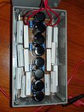
Ready to roll for experimenting tomorrow!
The resistors are screwed in and can be exchanged for other resistors, or shunts, if I want to experiment with different resistor values or patterns.
One question I find particularly interesting is this one: Will it make a difference if I switch the input and output for either positive or negative side of the paralleled capacitors? Is there an electric equivalent to the "Gegenstromprinzip" used for making heat exchange (or gas exchange et al) more efficient? http://de.wikipedia.org/wiki/Gegenstromprinzip http://en.wikipedia.org/wiki/Countercurrent_exchange
Maybe I should add in some fuses into the Ripple Buster, just in case, before I try it out....
This information may be used entirely at your own risk.
There is always a way if there is no other way!
Mik
Here some thoughts when working with higher voltage pack ,not to worry when dealing with 24 -48 volt
Your ripple reducing box with capacitor will act as a dead short until charged, essentially what you have is 14 1 ohm resistor in parallel or roughly 66 milliohm shunt across either side ( charger or batteries ) until all the caps are charge up .
Make sure that what ever supply you connect up is current limited ( your charger is since it use cap in series, the battery side will only be limited by its internal impedance, I would connect the charger side first then the batteries to lessen the inrush current ( or spark).
If you connect the battery side first then you will have a very large current charging up all the cap .
For example if you have 200 volt batteries and you hook it up first , the initial charging current for a instant could be as high as 2880 amps (doing simple math, it will depend on the battery SOC and internal impedance, but still a nice healthy spark ,if you use a switch it may weld .
With applying the charger first, the current is limited by the series cap and the isolation transformer, there will be a spark since you have cap across the bridge that may be charged , applying the AC power after making the ripple box connection , then connect the battery.
If you where using a inductor instead of resistor, the charging current will be limited by the inductance.
HEAT & LOSS & INEFFICIENCY RELATED DIRECTLY to IMPEDANCE
Mik.
The ripple buster is interesting. But is it really necessary?
If you consider that the ripple output of Freddy is a relatively small voltage compared to the charging voltage of the Vectrix (140volts) even as a percentage it is quite small, it shouldn't produce any detrimental effects.
Have you got a true measurement of the ripple voltage and the ripple current? How did you measure them and what are these measurements?
I haven't yet done any measurements but will try to collect some info in the next week or so.
The circuit you have drawn for your ripple reduction has some fundamental mistakes. There is no need to put resistors in both positive and negative lines, use the positive or negative line only. The reactance of the capacitors will provide a ratio of ripple reduction in conjunction with the value of the resistors. Bigger resistors will provide greater ripple reduction BUT they also generate more heat.
The suggestion of an inductor and capacitors is a better solution. Larger inductance equates to less ripple.
Let me have some figures for the charging voltage and current ripples (must be measured whilst charging the Vectrix battery) and I will endeavour to investigate any problems and produce a more practical answer to your concerns.
Keep smiling:-)
The Laird
Originally I wrote it up on Endless Sphere: https://www.endless-sphere.com/forums/viewtopic.php?f=14&t=12764&start=15#p239083
I'll reproduce it here:
I got a USB scope now, and it works somewhat. I cannot really tell if the thing is malfunctioning or not, but it sometimes seems to do strange stuff until the program gets rebooted and the hardware disconnected and reconnected.
And I cannot figure out how to calibrate it and set the zero point...
So all these results might be rubbish!
The thumbnails below lead to screenshots of the USB scope measuring the voltage drop across a 10mOhm shunt. The shunt is in series with the Freddy charger and the HP2 out of the BlueCar NHW10 battery (120s NiMH, 6 or 6.5Ah). Battery is empty, started at around 145V, at end of experimenting it was about 155V.
The title of the scope graphs can be seen below them once you have clicked on them, and they describe details about them: Charge current, motor run capacitor used to achieve this current, and either 12 Ohm resistor added in series or no resistor added. The resistor should probably be located between the smoothing capacitors, but for this experiment I simply put it in series with the charger output.
The actual zero line should be where 0.01V is; here is what the scope shows when no current is going through the shunt. It stubbornly claims -0.01V when it should be zero....
Any help with figuring out how to properly use this scope, and what the results mean (if anything), would be greatly appreciated!
The scope is a PoScope USB scope similar to this package: http://www.poscope.com/product.php?pid=13
If I interpret these graphs correctly, then the Freddy charger without resistor creates so much 100Hz ripple that the charge current becomes negative for a short time each 1/100th of a second.
With a 12 Ohm resistor, there is still a lot of ripple, but the current always goes into the cell, rather than reversing each hundredth of a second.
I have been using the 8microF / 0.64A setting to cycle the NHW10 HP1 5 times, without smoothing resistor.
Is that likely behind the 5% capacity reduction?
I think I causes no problem to add resistors to positive and negative lines, but it allows to have more surface area with better heat dissipation.
I think I better continue to experiment with the NHW10 batteries on the bench. I have many of them, but only one Vectrix battery, and that one is in the bike.
What I learn from charging these 6Ah 120s NiMH batteries should be applicable to 102s NiMH Vectrix batteries, within limits of course.
Thank you for your interest and help with this!
This information may be used entirely at your own risk.
There is always a way if there is no other way!
Using thumbnail pictures is not going to cut it - too difficult to follow them and compare.
But if I drop them in here in full size, the thread will come to a grinding halt on anything but the fastest internet connections and computers!
So I'll continue the "Universal Freddy" saga here: http://visforvoltage.org/forum/8426-taking-universal-freddy-limit.
This information may be used entirely at your own risk.
There is always a way if there is no other way!
The Ripple problem
I have measured the ripple on both voltage and current with Freddy in action on a virtually full Vectrix battery.
Voltage ripple measured across the charger out put terminals was 6.5 volts rms. This corresponds to 4.5% and is equal to 0.07volts ripple per 1.41 volt cell. This is not a figure that causes me any worry.
The Current ripple was greater at 0.09 amperes rms, representing a ripple of 30% on the charge current of 0.3 amperes. Again, I don't find this worrying and as far as I can establish there is little in any of the available specifications to indicate that ripple free charging is necessary, indeed, in some battery types ripple is beneficial.
Mik's graphs, in the main, show considerable high frequency pulses which cannot be the product of Freddy. It seems likely that the 'Scope being used is generating these h.f. signals. The output of Freddy is a series of positive half cycles of sign wave shape smoothed out by the capacitors (which follow the bridge rectifier) and also by the battery being charged. These half cycles are of 10mSec duration (each). There will be a very short duration of zero volts between consecutive half cycles due to one set of the bridge diodes switching off and the other pair of diodes switching on (this occurs for about 1.2 volts of the 680volt peak to peak input cycle and lasts for about a microsecond) you would be hard pressed to see this on a 'scope in the normal course of observations.
The comment of a 'reversal' of the charging current being 'removed' by the addition of a resistor is again likely to be an error in observation. The diode through which the current passes to reach the Vectrix battery would preclude any possible current reversal.
I am still doubtful of the need for 'ripple reduction'. However, if ripple must be removed, the better way by far to remove ripple is to use an inductor in series with the current and a capacitor across the output. An inductor of 0.1 Henrys and a Capacitor of 100 microfarads would give a ripple reduction of 4:1 with a volt drop of about 19.2 volts and no power loss (based on the original Freddy circuit). The use of a resistor is basically a 'loser' because of it's heat production / dissipation and power loss. To achieve the same result with a resistor (64 ohms) there would be a power loss of 5.7 watts
Bye the way, Looking at the circuit of 14 x 1 Ohm resistors and 8 x 100 Microfarad capacitors, this will give a ripple reduction of only 2:1 i.e. it will reduce the ripple to one half of the input ripple.
There is little more to be said on this topic. I believe in keeping everything as simple as possible as you may have noticed, remember the old saying "K.I.S.S. - Keep It Simple, Stupid".
I am willing to be corrected and will respond to any points which anyone wishes to raise, and NO I am not suggesting that anyone is stupid.
Keep smiling :-)
The Laird
How did you measure it? And was it with the R2 (10 Ohm) smoothing resistor from your original design or without it?
http://visforvoltage.org/sites/default/files/u4081/Circuit1rm.jpeg
And how did you measure this? (I'm not doubting your results, just want to learn how to do it properly!)
It's my first attempt at using a scope for anything (other than a few minutes in long ago school classes) and I am trying to work out what is malfunction/noise/operator error and what not. The higher frequencies in there, I thought, were due to the measurements being done at the highest sensitivity setting of the scope. I'm trying to measure mV across a 10mOhm shunt. Could the raggedness of the graph have something to do with the "floating" nature of the Freddy output? The scope is not grounded, I am running it through a galvanically isolated USB hub to avoid frying my laptop (again).
But despite higher frequency ripple of less than 5mV distorting it a bit, the 100Hz ripple from Freddy is the dominating curve in there.
Below is the measurement with the most similar settings to the original Freddy with 8uF motor-run capacitor but NO smoothing resistor. But this Freddy has 4 x 100uF smoothing capacitors (instead of 2) and charges a 120s NiMH battery (instead of the Vectrix' 102s NiMH battery):
I agree, and gladly! The only way that some reverse current could flow through my particular Freddy is through the volt meter circuit. It does not have a blocking diode between battery and voltmeter, like in your original design. (But on the Vectux I do have a blocking diode close to the battery in the Freddy charging connection.)
But even if a small reverse current through the voltmeter is possible, it would be totally impossible to spot it on the scope as a voltage across the 10mOhm shunt! It would be in the order of 0.0008A, causing a voltage of (0.0008A x 0.01 Ohm = 0.000008V = 8uV) across the shunt! Three orders of magnitude to small to see!
Therefore, the bottom end of the 100Hz ripple must be a measurement error.
Here is a diagram of the complete measurement circuit used:
I think this error is actually due to a lower frequency ripple going through the measurement! This ripple has about 13Hz frequency and is obvious in the 1.86A @ 46uF measurement:
I am by no means certain about this either! Ripple, as long as it always results in a positive current flow into the battery, could even ensure that parts of the cell with higher IR get charge when very low charge currents are being used, like here at 0.3A = C/100 for the Vectrix!
But my reason for trying to get to the bottom of the "ripple question" was the unexplained 5% capacity loss of a NHW10 120s NiMH battery after 5 cycles done with Freddy. Better safe than sorry!
Compare the below discharge curves at 12A from full charge. The 1V cutoff curves resulted after one charge with Freddy, the 0.9V cutoff curves after 5 or 6 charges with Freddy: Would that make you worry about your batteries?
Details at: https://www.endless-sphere.com/forums/viewtopic.php?f=14&t=12764&p=239085#p238069
The capacity loss of these cells has probably nothing to do with Freddy, but it is the first reason that must be ruled out in order to "Primum, non nocere"! (First, do no harm!)
The NHW10 cells were possibly just bouncing back from the "mother of all reconditioning discharges": A very slow self-discharge to almost zero volt! (That might of course be total nonsense.....like my idea to use the counter-current principle with a resistor-capacitor ladder.)
These batteries had been left uncharged for years, the 120s string had about 11V total before I got to work on it! One of the 6-cell sticks had 11mV only. Hence the titles for the posts on ES: "Is this battery dead as a Dodo, or a Phoenix?" and "A Phoenix or a Dying Swan?"!!!
I really don't know, but I do not want to test it by doing multiple charge cycles on the only Vectrix battery I have!
I don't know how to calculate the ripple reduction, but the test results shown at http://visforvoltage.org/forum/8426-taking-universal-freddy-limit look to me like a much, much better than 1:2 ripple reduction with the "Ripple Buster"! But those tests were done with the Freddy output (practically) shorted through the 10mOhm shunt and might not be applicable to a situation with a battery instead of the shunt.
Like this:
Here are some reduced size pictures to show what I mean. The full size pictures are in the new thread linked above.
The first graph shows the "ripple" at zero amps. It shows the "noise" only, whatever is creating it.
The second graph shows the maximum current my Freddy can do for a short time without blowing it's fuse: 2.89A with 46UF motor-run capacitors, but with the ripple buster in series.
The third graph shows the ripple at 3.16A (46uF) without the ripple buster:
That looks to me like almost complete ripple absence, rather than 1:2 reduction.
As I said, maybe it's all different with a battery connected. Or maybe this the answer to my question from a few days ago: "Would a single 14ohm resistor work just as well as the 14 separate 1Ohm resistors? (The original question had a typo in it, 7 instead of 14). And, quoting myself again: "I have a "hunch" that it will work better to have multiple steps in a ladder than just on big step".
If your calculation of 1:2 ripple reduction is correct for a 14Ohm resistor, then maybe my "hunch" was right and the ladder is much superior with many small steps compare to one big one?
However, tests with battery shall follow, and with my increasing knowledge of how to use a scope, the results should become more meaningful and reliable.
About the power loss due to the resistors: At 0.3A charge current you get 1.26W power dissipation through the 14 x 1R resistors; while 43W are going into the battery at 143V. That is a 2.9% loss. At higher currents the ratio gets worse, because of the exponential nature of power loss through a resistor (I^2 *R = W) and the linear increase of power to charge the battery (V * A = W).
No worries, I don't take it that way at all and am grateful for your answers!
I like to keep it simple, too! And the maths and theory are too complicated for me right now, so the seemingly complicated experiments are the way to keep it simple for me. Not that it's all that simple to figure out how to use a USB oscilloscope on devices that can produce hundreds of amps at hundreds of volts....
But it seems so much simpler than trying to figure it out theoretically!
This information may be used entirely at your own risk.
There is always a way if there is no other way!
Measuring ripple Voltage and Current.
First Point. Freddy is as original circuit, that is WITH the resistor. (Not that it will make much difference).
The Voltage Ripple measurement is relatively easy. An A.C. ammeter is used with a series capacitor across the power line to the battery. The diagram below shows the method. Meter B and C1.
How it works. The series capacitor blocks the D.C (all 144 volts of it) But allows the A.C. (the ripple) to pass to the meter. The meter range is scaled down (always start with a high setting) until a reading is obtained. This reading is the R.M.S value of the ripple and is adequate for this type of ripple.
Warning Following this measurement the capacitor will have a charge on it of 144volts. Short circuit the terminals of the capacitor before handling it or expect to become very shocked when you touch it.
The Current Ripple measurement Using meter A. Is straightforward the ten Ohm resistor will show a voltage across it's terminals which is related directly to the current passing through it. From Ohms law we can calculate the ripple current which is equal to the A.C. voltage measured divided by the resistor value in ohms. In my case I measured 0.9 volts across the ten ohm resistor which gives 0.9/10 =0.09amperes (R.M.S. because the meter gives R.M.S. values for A.C. - peak values are usually obtained using an oscilloscope).
Ripple Reduction Filters (Low Pass Filters in electronics terms).
These devices simply reduce the ripple according to ohms law / potential divider principles.
A simple filter is shown below.
In this filter I have shown an inductor OR a resistor in series with the output and a capacitor across the output. The ripple reduction is equal to the ratio of the reactances of R:C or L:C whichever is being used.
The reactance of the inductor is given by XL=2πfL. Where Xl is the inductice reactance in ohms
Pi =3.142 and f= frequency in hertz.
The reactance of the capacitor is given by XC= 1 Divided by 2πfC. Where Xc is the capacitve reactance in ohms. Pi = 3.142 and f = frequency in hertz.
Reactances are all measured in ohms and can be used directly in ohms law calculations.
In the circuit above, if R=64 ohms and C= 100 microfarads then the ripple reduction is 64:16 or 4:1
if L=0.1Henrys and C= 100 microfarads then the ripple reduction ratio is 64:16 or 4:1
Enough of this 'teach in'.
Mik's graphs show a ten hertz hum signal superimposed on the waveforms. The waveforms are obviously digitised but with no indication as to the scale (left vertical) it is hard to decipher. I can be fairly certain that what is shown is NOT the output of Freddy, The wave shapes are not what would be obtained from a charger output of this type. A typical charger wave shape is shown below (for a simple (Freddy type) charger).
The D.C. offset is taken care of by a x10 Probe on the 'scope input.
Will leave it there for now. I hope that I have addressed most questions. Comments and requests for more information is welcomed.
The Laird
I think it does make a difference! Heisenberg sends friendly greetings....
You have made the measurement with the 10 Ohm and an additional 10 Ohm resistor in the circuit, i.e. 20 Ohm. Therefore it makes perfect sense if you find that there is less ripple in the system than when I test with no resistor or a 12 Ohm resistor in series! I used a 10mOhm shunt; you used a 1000 times bigger shunt, plus the already 1000 times bigger resistor in the original Freddy. That's why you get different results.
The diagram is a bit small, but it looks like you put an AC voltmeter as Meter B in the diagram. Is it a voltmeter or an ammeter? Analog or digital TRMS?
As I said above, I think your measurement method very significantly changes the resulting ripple!
Here are two oscilloscope measurements during charging a 120s NiMH battery with Freddy. Both measure voltage across a 10mOhm shunt in series with the Freddy output. The first is without smoothing resistor, the second with a 12 Ohm resistor between Freddy and the battery, just where you put the 10 Ohm resistor for your measurement.
There is a very clear difference!
The Y achsis is in Volts, sorry I did not notice earlier that this is not shown in the display captures. It is beyond me why the USB scope software does not capture all the settings along with the measurement curves!
As above, the Y achsis is in Volts. Sorry about the missing label, I did not notice it! I think the waveform is insufficiently detailed because the voltage differences are so close to the maximum voltage resolution of the scope. It cannot show such fine details at such low voltage levels. A 0.3A current across the shunt only results in 3mV deflection on the Y-achsis.
If I use the x10 probe setting, then I cannot measure the small signal across the 10mOhm shunt at all.
[/quote]
I'll try to measure with a different X-achsis resolution to show that it is the correct waveform. But I know already that it is the Freddy output, because it happens to appear and disappear on the scope output screen just at the right times, every time; and never when Freddy is not putting current through the shunt!
Thanks for the explanations. I hope I'm not getting too annoying here, but the measurements seem to contradict the predictions at the moment....
It might all be due to my operator error and inexperience with the oscilloscope, but for now I think my measurements are relatively accurate.
That does not mean that the ripple does damage - so far I can only measure the ripple, but not it's effect on batteries.
This information may be used entirely at your own risk.
There is always a way if there is no other way!
It's getting too complicated
Lets clear the table and look at this afresh.
The issue here is a/ whether the ripple on Freddy is causing a problem as in loss of capacity. and b/ how much ripple is Freddy putting out?
With regard to issue a/, The battery in question appears, by Mik's report, to be losing capacity following five charge / discharge cycles. There are limited possibilities here and they are.
1. The battery in question is causing the problem.
2. Freddy is causing the trouble in some way or other.
As Mik has possesion of the battery and Freddy I can only speculate on the cause of the problem, however, Mik has said that the battery was in a very sorry state at the start of this process and from this starting point I will suggest that the battery has actually been improving over each charge / discharge cycle and that it's terminal voltage at full charge is rising with each charge. This could result in the battery requiring the charge to be continued until the higher terminal voltage is reached. Basically, the battery is not now receiving a full charge.
It is normal for battery terminal voltages to be higher when new and to lower with aging. If an 'old' battery is being resurrected then it is reasonable for this process to reverse to some extent.
I have never experienced a battery being damaged by charging except where the 'ripple' was actually caused by a fault and produced a massive short duration pulse of charge current at a relatively slow pace.
If the ripple output by Freddy is suspected of causing the problem then the sure way to prove it is to charge the battery by another means and check the result. This is sound engineering practice when there are too many unknowns to deal with easily.
Back to the ripple measuring
The ten ohm resistor shown in my measuring diagram cannot affect the shape or amplitude of the ripple, it is a passive component, it can only convert the current flowing through it into a voltage across it which is exactly what we need to measure the ripple current. To change the ripple shape you need more than a resistor. The value of the resistor is largely irrelevant as it has no effect on the wave shape. The bigger the resistor the greater the voltage developed across it and the easier to measure. Freddy can provide any 'lost' voltage again without changing the waveshape.
Both of the meters are voltmeters. It doesn't matter digital or analogue, we are only measuring the ripple content in terms of r.m.s. value. The shape is highly predictable from the circuitry and is of little relevance.
If Mik's statement on the voltage scale is correct then there is no problem. However, the wave shapes are not as expected (even if there were fault conditions present in the charger) and the amplitudes are far too small. I would expect to get a peak to peak ripple value which is larger than the r.m.s. figures.
To get acceptable size waveforms on a 'scope it should be a.c. coupled and the scale set to display the expected size of waveform. The times ten probe would only be used to measure the d.c. level of the waveform in a case like this.
The thinking is getting too involved for this relatively simple problem, keeping it all simple will help immensely.
The Laird
If I understand what I read, this "scope" is a probe/USB input to a laptop with a "scope" program on it. My first thought when looking at the waveform was 60Hz hum as I have seen 1000 times when picking up the tip of my Tektronix probe. My second thought is the well documented problems with any USB input in an electrical noisy environment. Therefore without comparing the observed waveform to that on a scope with a shielded input, I would have a hard time putting forth any judgment on the Freddy other than to say ignore the hum. The battery is not being affected by it.
Further Work on Ripples
Some pictures of 'scoped waveforms on Freddy.
First is of Freddy powering straight into a ten ohm resistor.
'scope settings are Y=2volts / division
x=5mSec / division
D.C. coupling with wire connections.
Second is Freddy showing voltage ripple. The ten ohm resistor has been replaced by an eight cell NiMH Vectrix battery block.
'scope settings as above
Third is of Freddy powering the battery again but with A.C. coupling and Y=10mVolts / division
Fourth is of Freddy as above but looking at the current waveform across a ten ohm resistor in series with the current line.
settings are D.C. coupling.
Y= 2 Volts /division
x=5mSec / division.
When a 100 microfarad capacitor was added to the ouput of Freddy, the ripple dropped from 4.0 volts to 3.5 volts peak to peak.
By calculation the current ripple is equal to V divided by R. = 4.0 divided by 10= 0.4amperes Pk to Pk equaling an r.m.s. value of 0.14 amperes R.M.S. ripple.
The current ripple of 0.14 Amperes on a current of 0.6 amperes equates to 23%ripple.
The voltage ripple is very low at only 10 millivolts pk to pk.
The above is all done with only eight cells. The current ripple, as a percentage, will be the same when charging the full battery of 102cells. The voltage ripple will also be the same on the full 102 cells
Does this help?
The Laird.
Interesting idea!
I was expecting the battery to improve with each consecutive charge, with capacity at 12A to 0.9V cutoff being the measure of such improvement. But I got a capacity reduction.
I have just gone over my detailed records and I found the likely reason!
It was the "Increased self-discharge rate with higher temperatures trap"!! That one gets you every time you park your Vectrix in the sun, or do an EQ charge in hot weather. End the charge at 40degC or more, and the battery empties a significant amount of it's charge over the next few hours, due to heat related increased self-discharge rate.
In this case, the re-awakened NHW10 BlueCar HP1, the first full charge with Freddy ended with 40degC cells (or thereabouts). I let the battery rest and cool overnight, then gave it a 1hr top-up charge:
Charging at 0.6A for 1 hr Nr. 13: 2010-01-15, 0558am: At end: 174.2Vmax; 174.0Vactual; 322.6Ohm; 32.8degC;
Nice and full it was, and only 32.8degC warm! Then I let it rest for about 9hrs and began the capacity testing.
Four Freddy charges followed, interspersed by discharging (through another gizmo I made from 240V light bulbs and a SMR from the Prius) without accurate capacity measurement.
Then came the recharge Nr. 5 and the following capacity tests on the 20 "sticks". And that's where the error occurred!
Having become more confident with the semi-automated charging through Freddy and a timer, I finished the charging process with a 1hr charge around midnight, unattended.
The records read: 2010-01-29, 2255pm: 1hr at 0.6A: 25.6degC; 321.5ohm; 160.2V at start.
0.63A at start. 2356pm: 171.6Vmax: 321.9ohm; 28.8degC restarted for further 1hr.
2010-01-29, 2358pm: 1hr at 0.6A: 0730am: 171.9Vmax: 327.0ohmmax; 322.1ohmactual; 162.1Vactual; 30.8degC now.
full
The 327.0 Ohm (automated peak recording) mean that the battery got to about 44degC, about an hour after the charge had finished at 0100am. Vmax had been 171.9V due to this higher temperature during charging, as opposed to the 174.2V during the first charge at 32.8degC.
The I started capacity tests about 9hrs after end of full charge, and got 5% lowered results.
Then I got worried and repeated the "charge to full whilst hot", and tested just 2 sticks. Again, the capacity was lower than the first time.
A 9hr rest period starting with 45degC causes easily 5% reduced SOC, when compared to a 9hr rest period starting with 33degC!
Mystery (part 1) solved!
This way of checking it would only work if the capacity loss is temporary. Had I not committed the above mentioned blunder (rest period at different cell temperatures), then there should not be any capacity changes because I always used Freddy to charge these Prius NHW10 batteries. So the result should be the same each time, unless the capacity loss is irreversible.
The way to check will be to charge with Freddy, let cool, top-up for one hour, then rest and test. Like the first time. Or, I could just give up and assume the mystery is solved (which it most likely is)!
I'll reply to that later - just noticed your next post with the scope photos and need to have a good look at it all.
May I suggest we continue this in a new thread? Maybe the one I started already http://visforvoltage.org/forum/8426-taking-universal-freddy-limit , or any new thread.
Otherwise we will bog down this thread - certainly one of the best in the Collaborative Handbook - and make it hard to access. It happened to me before, open the following link with a slowish internet connection and you will see what I mean: http://visforvoltage.org/forum/3582-vectux-quotopen-source-vectrixquot
This information may be used entirely at your own risk.
There is always a way if there is no other way!
I have several automatic NiMH chargers so I will put some batteries in them and look at the charging waveform. I expect to see all manner of tiny ripples in the output. I can not imagine this is of any concern to the life of the battteries.
I don't understand what you are saying as in one line you state the ripple voltage as 4V p-p and then 3 lines later you state it as 10 millivolts. If it is 10 millivolts, what is the concern? Do you expect to see absolutely pure DC from the charger? Take a look at a computer PS and you will have an appreciation for what it takes to get a few 100 milliamps of clean DC. Take a $20 Autozone 12V battery charger and look at the output on your scope. My WAG is the ripple in Freddy output has nothing to do with any problem this battery pack has.
As a few years have passed since the problem first came up with this NiMH battery pack and this is a relatively expensive scoot, why don't people just buy a LiFEPO4 battery with charger and get on motoring? If I had a $6000+ scoot, I sure wouldn't be sitting around for years expecting some corporate flakes to do the right thing, even if they were responsible. I've had 3 expensive diesel engines fail that should have been covered under warranty, but weren't. Each time, I bought a new engine and got back truckin' as fast as I could, before I went broke. Sitting and cursing Cat or International, would not put food on the table. Playing with junk batteries and chargers that just won't work is a good science project, but won't put much of a grin on yo face.
I may be totally wrong here, but I think you misread the internal resistance number by a factor of 10. Internal resistance of the Vectrix' NiMH cell is actually:

Internal Resistance : Below 12mΩ (ref.)
If we take this number into your calculation at 25A current draw (60-65km/h), that means 25A x 25A x 0.012Ω x 102 cells = 765W
At 100km/h, the current is aprox 90A: 90A x 90A x 0.012Ω x 102 cells = 9914W.
Am I dead wrong?
The Lairds maths are correct.
You misread the spec sheet, because it is for a 10 cell module, not for a single cell.
This information may be used entirely at your own risk.
There is always a way if there is no other way!
Aha, thank you! I knew that I must had done a mistake somewhere.
I'am thinking of building an Equalizer charger as originaly specified (not the MiK modified version) and I noticed this specification requirment (see above) that the resisters have at least a six hundred volt rating.
Would puting 3 ordinary resisters in series be satisfactory? as for example instead of using the 1.0 MegOhm .5 watt resister as specified I would use 3 330K ohm .5 watt resisters in series. I found this on the internet that seems to substantiate this;
"Resistors must be sized for power and multiple resistors used in series, if necessary, to satisfy the resistor voltage rating."
last line of 3rd paragraph
http://www.innovatia.com/Design_Center/Start-Up%20Circuits.htm
Yes, adding resistors in series to meet a voltage requirement is fine. (I've done this for microwave-discharging for example which needs about 2.7kV spec, or a chain of 10 resistors in my case).
I'm not sure you really need a x2 safety factor; that seems excessive. In general simply meeting the spec should be OK. The resistors will have manufacturing tolerances built-in to their datasheet spec, so if they say they'll take 160V then at least 99% of them will be fine with 160V. You might sensibly add 20% for paranoia purposes.
Picking a random datasheet, Caddock's MG series of high-voltage resistors specifies that overvoltage up to 150% is OK for short periods, and even their weediest resistors will take 600V:
http://www.google.com/url?sa=t&source=web&cd=4&ved=0CCcQFjAD&url=http%3A%2F%2Fwww.caddock.com%2FOnline_catalog%2FMrktg_Lit%2FTyp...
Wookey
Sakura s50 (Efun A)
Hi Anderson,
Resistors have a voltage rating. Yes, you can put them in series to attain a higher voltage rating.
Precautions. Allow for the 'tollerance' in the resistor values and always use equal value resistors.
In Practice, for example, to make a 1 MegOhm 0.5 watt resistor at 300 volt , use 3x 330KOhm resistors of at least 200 volts each and at least 0.5 watts each. This should provide a sufficient safety factor. ALWAYS use identical resistors in this practice. Identical in voltage, resistance and power ratings.
Hope that this helps
The Laird
Hi Wookey,
I hope that I am not treading on your toes. I always go for a high (x2) safety margin, I come from an age where tolerances were wide and failures common and voltages quoted in circuits were often wide of the mark.
'Freddy' can produce voltages (within the circuitry) of up to 367 (on a 260 volts A.C. input) more commonly up to 346 on a 245 volt A.C. input. The resistor voltage values were chosen to take account of this, and have spare 'capacity'.
Best wishes
The Laird
Hi The Laird,
I'm Planning to build your charger to try and save my battery pack which I supect either being unballanced either having dead cells.
Before I start building it based on your hand-drawing at the begining of this post, do you have an updated version of this schema, or is it still valid and working fine? Also, would you have some pictures of the inside of you charger? And some of the connexion in the Vectrix to see where you plugged the Vectix side circuit?
thank you,
Afo
Afo: I guess the easiest way for you is to order one or two power-suppys on Ebay.
http://visforvoltage.org/forum/12650-topping-charging-300ma-ebay-led-powe-supply
There are various models, also with higher output then 90V.
I guess it would have been cheaper and faster to buy these. But with the help of my local dealer and The Laird, I managed to build my own Freddy: 100€ of components and 1 day, including time to go and buy the components:
I plugged it to the vectrix for 2 hours as a check. No raise of the temp which stayed at 14°C and V went from 140.1 to 140.7. Then I plugged in for the whole night, then V went to 144.8 and temp 16°C. I left the Vectrix alone for a day to get temp down. V went back to 141.4 and temp 14°C.
Then I ride for 30km, V down to 128V and raise of temp only +2°C. So no extention of range but better on temp raise. Before on the same commut I was getting +3 to +5 degres. I guess my pack is EQ now. I hope the get back some better range after few charge/discharge cycles.
I'm hoping someone can help me with a problem I am having with my Vectrix VX-1. While I was laid up following surgery, I inadvertently let the batteries on my VX-1 discharge completely. Now the scooter is completely dead. When I plug it into an outlet, nothing happens - no lights, no fans, nothing. Is there a way for me to get these batteries to recharge again, or are they ruined after having been discharged now for a few months? Thanks in advance for any help. Steve
Pages