
This topic started earlier in this thread: http://visforvoltage.org/forum/7912-nimh-battery-problems-and-cures
In order not to clog up that very very interesting original thread I continue here.....
I intend to use lots of large size screenshots from oscilloscope readings, so that the readers can easily follow and hopefully answer my questions.
That way, those well educated and presumably quite busy forum members with the necessary know-how will hopefully be able to continue to contribute, without having to click away through layers of thumbnails to find out what the heck I am going on about!


Remember this charger is potentially very dangerous! It is anything but foolproof - nasty, even fatal shocks can result from incorrect handling. This is a prototype, not a mature product! Particularly the "Ripple Buster" in it's current form is a disaster waiting to happen - due to inrush current and due to potential shock long after disconnection due to lack of resistors to automatically discharge the 800uF capacity.
Ideally, both devices would be combined into just one. After a bunch of tests, we might all know exactly how to do it!
Here is the schematic for the "Universal Freddy" charger I have used for the experiments / measurements to follow below:
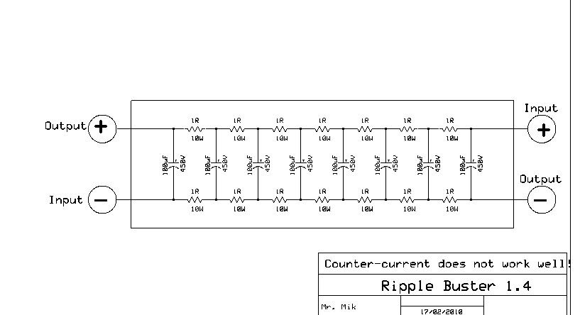
And this is the schematic for the "Ripple Buster" prototype used:
This is how Freddy looks in real life:
And here is what the "Ripple Buster" looks like:
This information may be used entirely at your own risk.
There is always a way if there is no other way!
The following oscilloscope measurements were done with a PoScope basic 2 USB oscilloscope.
All the measurements were done by measuring the voltage drop across a shunt http://www.jaycar.com.au/productView.asp?ID=QP5410 with 10mOhm resistance. The shunt is shorting the output of Universal Freddy, without any battery to be charged, just for the purpose of this test.
There are three different measurements for the same motor-run-capacitor setting below, always in this order:
1) XXuF with "Ripple Buster" in normal (concurrent) connection.
2) XXuF with "Ripple Buster" in counter-current connection.
3) XXuF without the "Ripple Buster"
"Counter-current" is something I just wanted to try out, it's when it gets connected like this:
The result up-front: The Ripple Buster works very well in normal connection mode, I cannot see any remaining ripple. It does of course get hot...
In "counter-current" mode, the Ripple Buster does not work as well, but is still much better than nothing.
The ADC (= ampere DC) number given was measured by a DMM across the same shunt. It concurs with the scope measurement results.
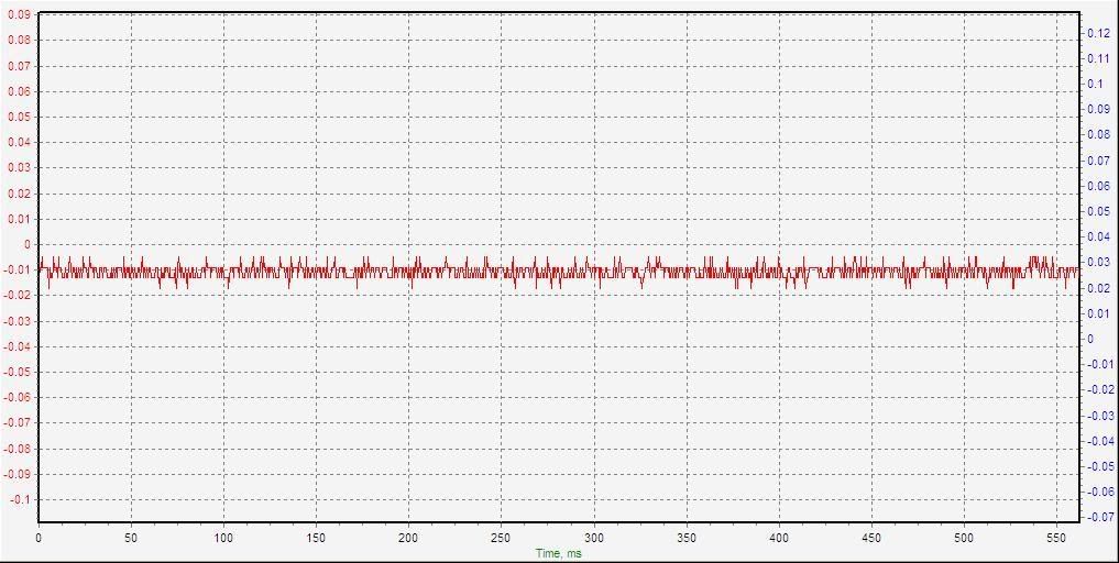
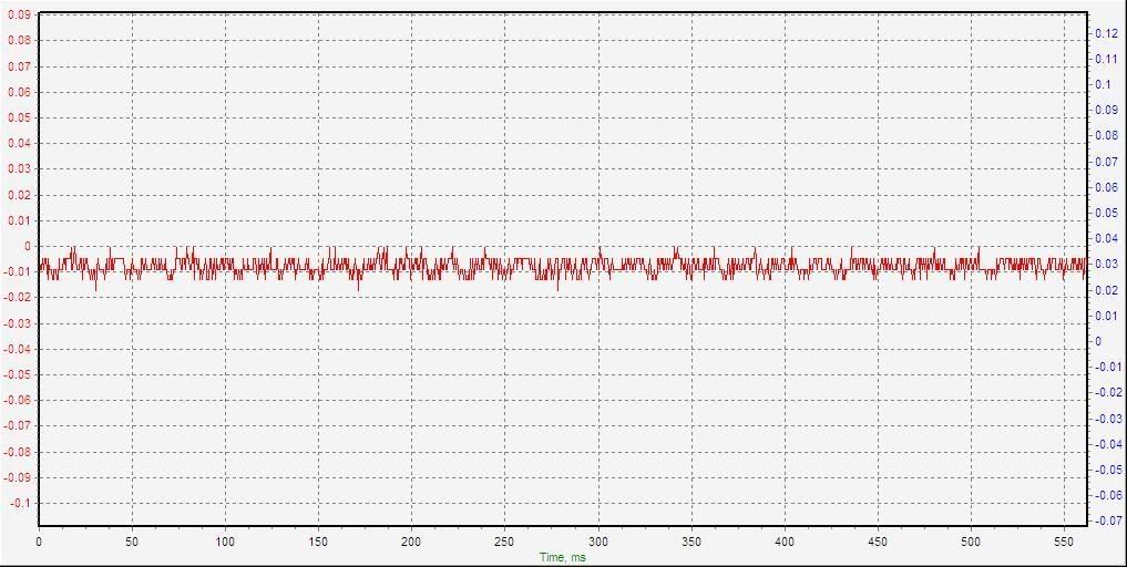
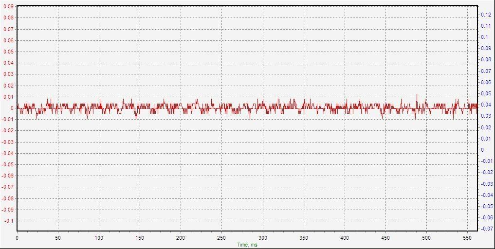
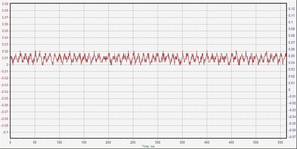
Here is the first measurement, it shows where the zero line really is (at -0.01V) and the noise without any ripple.

Settings: 00uF 0ADC with buster concurrent:
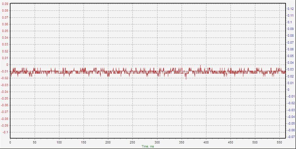
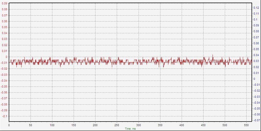
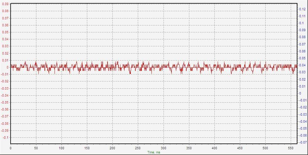
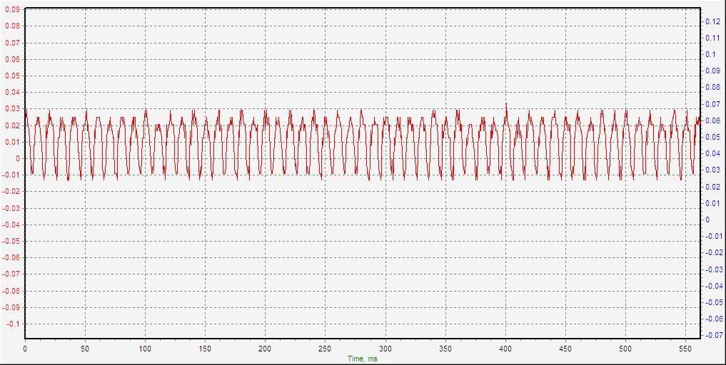
With the Ripple Buster in counter-current mode, it looks like this:
Settings: 00uF 0ADC with buster counter-current:
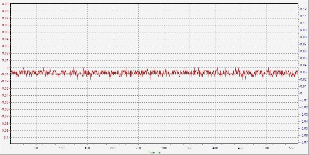
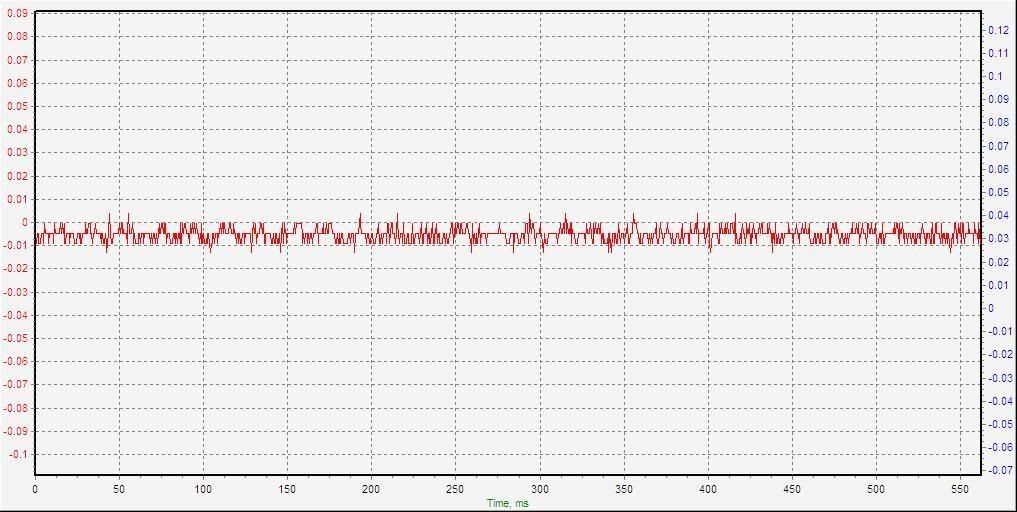
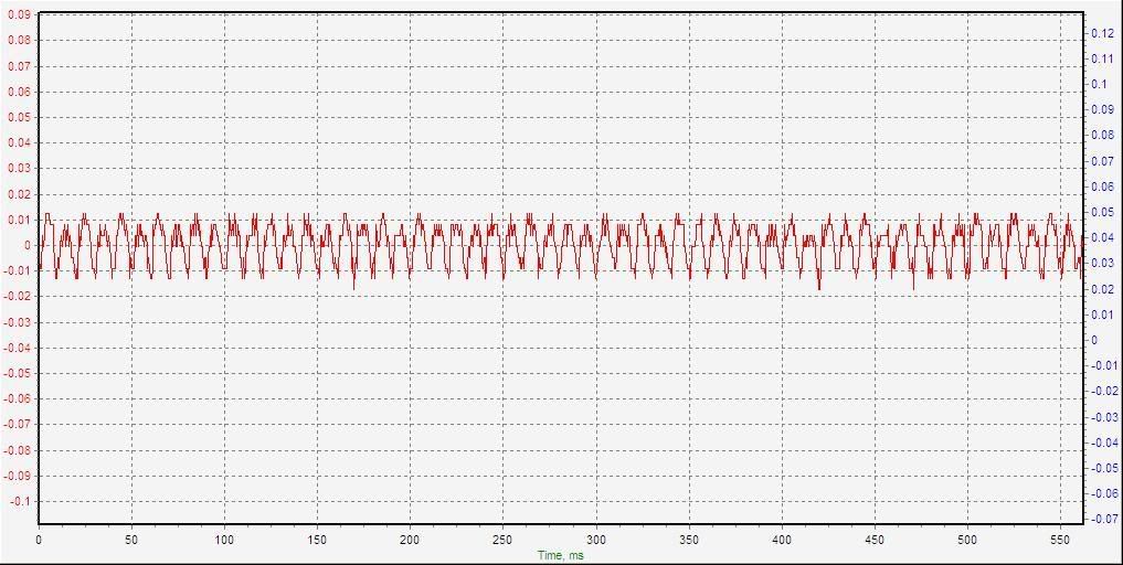
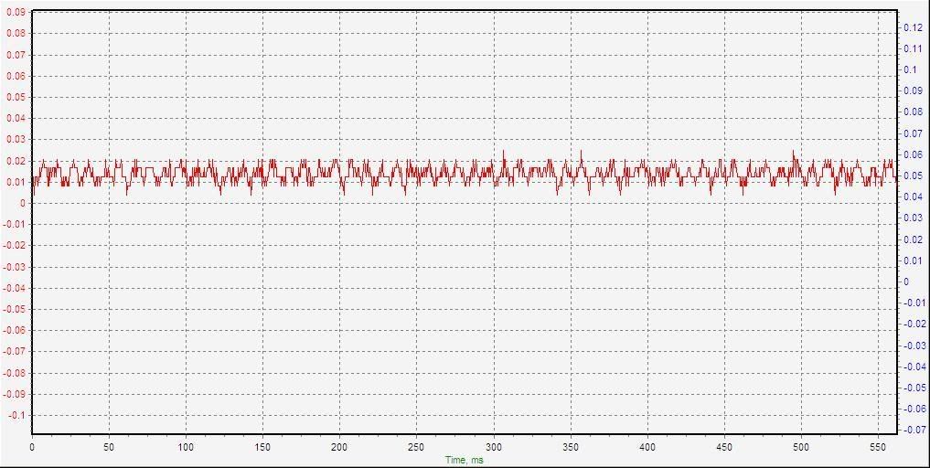
The third test at zero amps, this time without the Ripple Buster:
Settings: 00uF 0ADC
Of course, all three look the same, because no current is flowing to cause any voltage drop across the shunt. Just checking, to be sure to be sure....
This information may be used entirely at your own risk.
There is always a way if there is no other way!
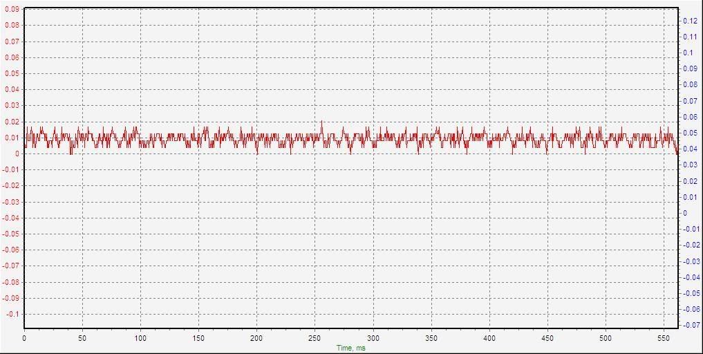
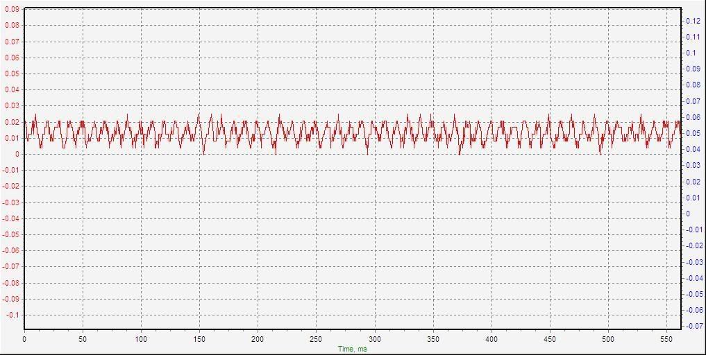
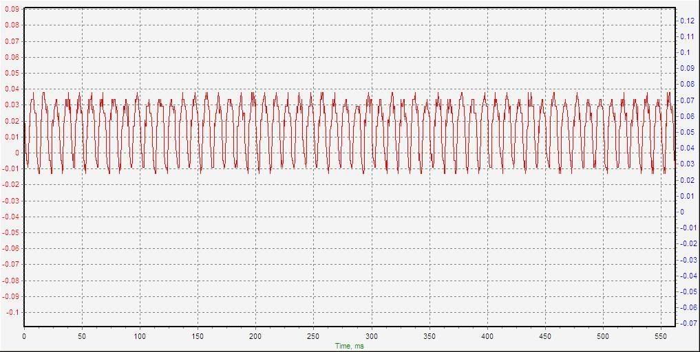
Here are the three measurements using the 4uF MR capacitor in the charger:
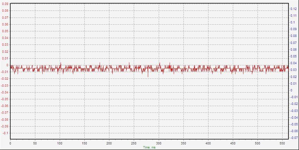
Settings: 04uF 0.27ADC with buster concurrent:
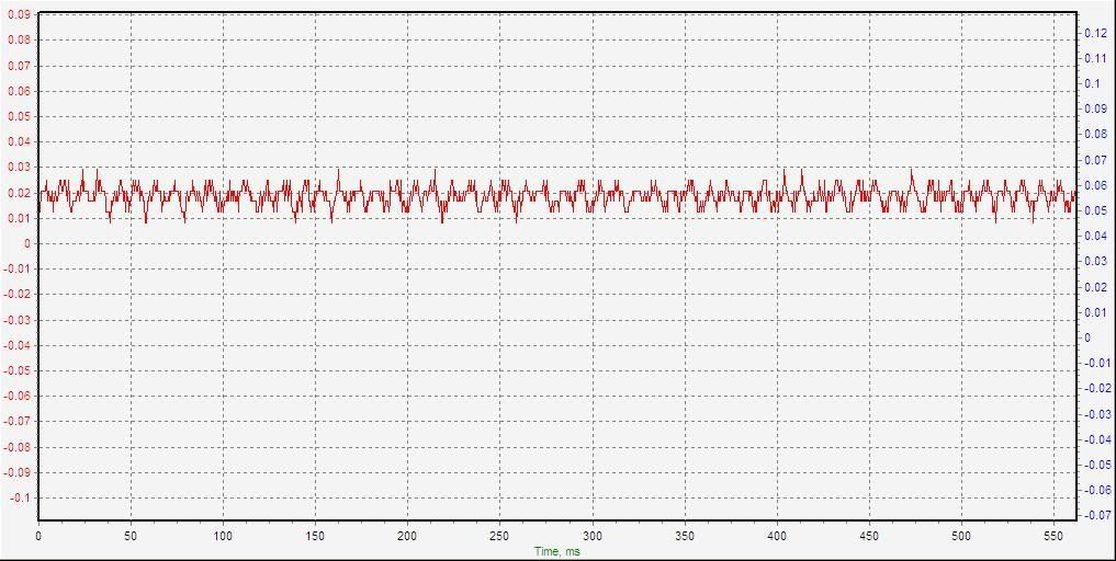
Settings: 04uF 0.27ADC with buster counter-current:
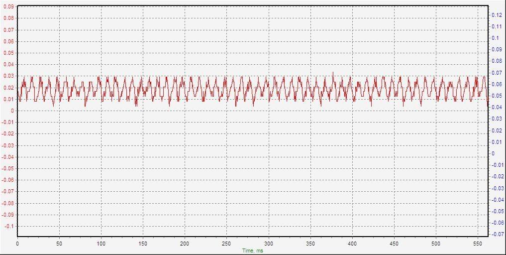
Settings: 04uF 0.28ADC:
Not much difference, if any, at that low current level!
This information may be used entirely at your own risk.
There is always a way if there is no other way!
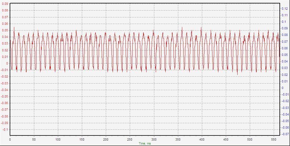
The three tests with 8uF setting:
Setting: 08uF 0.55ADC with buster concurrent:
Settings: 08uF 0.56ADC with buster counter-current:
Settings: 08uF 0.57ADC:
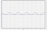
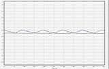
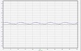
It's becoming more obvious that higher current flows without the Ripple Buster, and there is some ripple showing up in the measurement without the buster.
This information may be used entirely at your own risk.
There is always a way if there is no other way!
Third set of three measurements: All with 16uF:
Settings:16uF 1.06ADC with buster concurrent:
Settings: 16uF 1.08ADC with buster counter-current:
Settings: 16uF 1.13ADC:
Differences in current and ripple becoming obvious...
This information may be used entirely at your own risk.
There is always a way if there is no other way!
The three measurements with 30uF:
Settings: 30uF 1.95ADC with buster concurrent:
Settings: 30uF 1.97ADC with buster counter-current:
Settings: 30uF 2.12ADC:
It's pretty obvious now!
This information may be used entirely at your own risk.
There is always a way if there is no other way!
Now to the first measurement with parallelled motor-run-capacitors: 30uF + 8uF = 38uF:
Settings: 38uF 2.41ADC with buster concurrent:
Settings: 38uF 2.40ADC with buster counter-current:
Settings: 38uF 2.67ADC:
This information may be used entirely at your own risk.
There is always a way if there is no other way!
Last not least, 46uF tests, the most my charger can do before the 2A slow-blow fuse does it's job....had to work fast for these tests:
Settings: 46uF 2.89ADC with buster concurrent:
Settings: 46uF 2.89ADC with buster counter-current:
Settings: 46uF 3.16ADC:
The differences are extremely obvious at the higher current settings!
This information may be used entirely at your own risk.
There is always a way if there is no other way!
Just to make it easier to see how similar the curves for 0A and 2.89A are, here they are next to each other:
Settings: 46uF 2.89ADC with buster concurrent

Settings: 00uF 0ADC with buster concurrent:
I'm sure the ripple left in there, once it's gone through the "Ripple Buster" is insignificant - and any battery should be able to tolerate it!
Next, I will test with NHW10 batteries connected; then, use it on the Vectux battery to prepare for the battery analysis and cell replacement.
The biggest problem at anything over 1A constant charge rate is that the resistors in the Ripple Buster get too hot; they would overheat the capacitors sooner rather than later. With the lid off, at 1A, they stabilise at about 75degC (25degC ambient). I need to add perforations to the housing, and maybe a mesh lid rather than plastic, to allow air flow.
The power loss at 2.89A is: 2.89A x 2.89A x 14Ohm = 116.9W
If it was charging a battery at 150V with this current, then this would require 2.89A x 150V = 433.5W
116.9 + 433.5 = 550.4W
116.9 / 550.4 = 78.8% efficient! That's probably an over-estimation, because the bridge rectifier and the output diodes also get warm a little bit, but it's not too bad at all for a fairly cheap and easy design!
Or is there some error in these calculations?
This information may be used entirely at your own risk.
There is always a way if there is no other way!
Thanks for taking the time to put the scope on Freddy and taking the pictures! Most helpful!
I'll try to repeat these test with my USB scope to get a bearing on how it works...
Here is my scope's result with similar setting:
So far, so good!
There are more divisions on a single screen with the USB scope. Therefore, rather than setting the V/division value identical to the settings on The Lairds scope, I have to set the V/ screen value the same.
I cannot figure out how exactly you connected the scope to the charger and battery. The scope seems to show 10V without ripple. So the setting is different from the first one.
Same here, not sure how you connected the scope. How do you avoid a ground loop in the scopes ground pin? Your Freddy (without isolating 1:1 transformer) would cause a nasty short if it's output was grounded.
This information may be used entirely at your own risk.
There is always a way if there is no other way!
Competition Time?
Mik Said
Observation. Mik's 'scoped waveform shows a 'non smooth' wave. The true shape is that on the Tenma 'scope above. The distortions on Mik's waveform is due to the digitising of the signals by the computer system.
The second pair of waveforms
The settings are the same as in the first one.
In the first case the 'scope was measuring across the resistor which was attached to the output of Freddy. In the second set the 'scope was measuring across the eight cell battery which was attached to the output of Freddy.
In the third 'scope photo the 'scope settings were as per the previous photo with the exception of the probe coupling which was set to A.C. coupling and the Y sensitivity which was set to 10 millivolts per centimeter (or per division).
If you look carefully you can see the A.C. coupling of the 'scope on the vertical slider control, bottom right of the picture. On the first two pictures the slider is 'down'(the D.C. position) in this one the slider is 'up' (the A.C. position).
There is no 'trick' or 'foul play' going on here. I am simply using the 'scope to it's best advantage to achieve the most accurate results. The 'scope used is a professional 'Tenma' and the rest is down to my engineering skill.
In order to 'scope the output of 'Freddy' which is a balanced output (balanced either side of the mains neutral (essentially an Earth connection) I have removed the 'scope's earth connection. (This is a common and essential engineering practice, but NOT one to be practiced by other than a competent engineer) This allows the body of the 'scope to 'Float' electrically to the potential of the signal being measured. There are many precautions to be taken when carrying out this practice and it can be very dangerous. Again this is not to be attempted by the untrained - you have been warned.
I am an electronics engineer. I know the dangers. Others (non Engineers) may think that they know the dangers BUT they could be mistaken
I will comment again.
'Freddy' is a potentially hazardous piece of equipment and I have previously given warnings of this.
Freddy was designed to do a specific job under specified conditions. I have offered to provide help if anyone has a specific need for a Freddy type circuit, but you have to ask.
I am unhappy about the changes being made as many of these changes bring extra hazards, many of which are not at all obvious to the untrained eye.
The ripple which is put out by Freddy in it's original form and the use for which it is intended are, to the best of my knowledge, harmless to the NiMH battery when used for the occasional 'Equalising' charge. I have, in fact, completely
charged a Vectrix battery from empty to full, using Freddy. I use Freddy on a regular basis, I do not have any problems with this.
I suggest That it is time to stop experimenting with this potentially hazardous piece of equipment. I am seriously concerned that there are people out there reading these pages who may be tempted to try their own 'experiments' with this circuit. I do not wish to see anyone being injured (or worse). I provided a circuit and information freely for anyone of sufficient skill to build and use in comparative safety. I did not intend that others should change or alter it in any way. I asked that anyone requiring something different should contact me via the message system, and I would help sort it out or explain as necessary. That offer still stands but right now I think that it is time to stop the 'public experiments' in the interests of safety.
I am not 'getting at anyone' but I do feel that this topic is in danger of becoming a safety issue. My sincere apologies to anyone who might feel offended by this post. No offence is intended, I am simply putting my cards on the table.
Stay safe and keep smiling:-)
The Laird.
Sorry if I made you feel uneasy about all this!
I did not mean to imply that you use foul play or any such thing. I just want to understand how you get to the results you get.
I believe your results are most likely correct, so if I manage to reproduce them, I understand it better, that's all.
You are of course right about the safety concerns. That is one of the reasons that I use the 1:1 isolating transformer with this charger. Even with this, it is dangerous!
I connect the USB scope to the computer through a galvanically isolated USB hub. The ground pin of channel A or B gets connected to ground and the probe tip of the measuring channel to the floating output from the isolated Freddy. The ground pin of the measuring probe also gets connected to the output of Freddy, but on the other side of a resistor. In other words, I am grounding the output of the Iso-transformer-Freddy, and completely isolate the scope from the computer.
The isolating transformer might be behind some of the strange results I get; it creates a lot of electrical noise on the workbench! The scope does not need to be connected to anything to record waveforms as soon as I turn on the transformer. When I turn on Freddy, the noise gets a lot stronger. But with the above mentioned earthing the noise seems to be eliminated.
Yes, I have changed "Freddy" from your original, purpose designed specs, in order to include more options based on the same principle. And yes, this could cause problems that were not present in your original design. I do not recommend to anyone to build this complex, Anti-KISS-Freddy! It is too complex. But as a test instrument it can serve the purpose to develop another version of Freddy, purpose built for a different application; the resulting, different Freddy will again be following the KISS principle, like your original!
For example:
One might want a version that charges a Vectrix NiMH battery at 0.6A or 1A or 3A.
Or one might want a Freddy version that charges a Prius NiMH battery, ranging from 240s down to 168s in the later models.
And how about the LiFePo batteries people are beginning to try to put into their Vectrix (well, rather their Vectux, really!)? Will we need a Freddy version to help the BMS top-balance the cells by applying a charge current of less than 3A at will, independent from the stock charger? Will current ripple interfere with the High-Voltage-cutoff-detection mechanism in that BMS?
In order to get around this problem, and the difficulties it causes in comparing the results between your original setup and the different animal I have built, I decided to go back to the first model I built and measure what it does. It was built to the original specs, and I later shorted the 10Ohm resistor between the 2 x 100uF caps. That shorting cable is easily cut to restore Freddy to "Original Freddy" for testing.
I'll briefly reply to some parts of your last post below, then drop in a series of measurements which I had just prepared ready for posting before I found your next post.
Then, I'll continue it off-forum because it seems to cause misunderstandings and concerns rather than achieving progress!
No, not wanting to compete with you! I don't like loosing and this is your game and home turf! The statements you made about the insignificant ripple etc of the original Freddy are probably correct. But with the changed design of the "Anti-KISS-Freddy" the ripple seems to become much stronger. And I want more current at higher voltages, because the 350V Prius batteries cannot be equalized effectively using the original 8uF Freddy.
I also think that C/100 may be too low for an equalising charge, but that is another topic and my tests to get clarity about this are on hold at the moment.
Could it also be due to the interference cause by the 1:1 transformer?
I meant that the Y-achsis is set to show 5V / division, unlike the 2V / division above.
Thanks, I understand how you connected it now. As I said before, I use the 1:1 isolating transformer; I understand that just one mistake can kill you when using the type of balanced output that Freddy produces without the transformer. And I think that once I have connected the USB scope to ground and to the charger and battery as I described above, one mistake can also kill. One pole of the battery is then grounded, making the other pole "live" with regard to careless fingers touching just one part of the battery... but I do not leave anything exposed which is not already grounded.
Sorry, I guess I got carried away by my curiosity and adventurous spirit! I did not do it to cause you any headache.
No worries! :-)
I understand your concerns about doing this in public. Sometimes I am worried about that, too, and at other times I think it's peoples own fault if they do not heed warnings and get themselves hurt! Anyone can find instructions for much more dangerous devices than Freddy on the internet!
Here is the post I had prepared earlier:
I worked out that I can use a 1 Ohm (1R) resistor instead of the 0.01 Ohm shunt (0R01) to measure the current
ripple with the scope.
This introduces a larger change to the ripple than the 0R01 shunt, but the signal is 100X larger and clearer to see.
The changes caused to the measured current ripple are small when using this 1R.
I have also resurrected the original Freddy charger to ensure I am measuring the same device as The Laird is
measuring. That is, except for the 1:1 isolating transformer, I will keep using that for now for safety reasons.
The "Original Freddy" is the one with a 8uF motor run capacitor and a 10R resistor between two 100uF electrolytic
capacitors on the output side.
The two rows of thumbnails below show a result that baffles me a bit: The Laird seems to be right about the small
effect of the 10R smoothing capacitor in the original Freddy, but a 10R resistor put in series with the Freddy
output and a 120s NiMH battery has a strong effect on current ripple!
In both rows the scope is measuring volts across a 1R in series with Freddy and a 120sNiMH battery.
Y-achsis: Volts (with 1V representing 1A current across the 1R shunt)
X-achsis: 5ms / division
First row: Original Freddy
Second row: Freddy without it's 10R between the two 100uf caps.
First column: charging 1R and 120sNiMH.
Second column: charging 1R +10R and 120sNiMH.
Third column: charging 1R +10R +10R and 120sNiMH.
(Click thumbnails to enlarge)
(Click thumbnails to enlarge)
This information may be used entirely at your own risk.
There is always a way if there is no other way!
Hi Mik and all interested parties,
Like I said, No offense intended and I hope none is taken.
First, the answers to some questions contained in Miks's post of 24th February.
My results are correct (despite the odd scripting error). It is a matter of connecting the oscilloscope chassis to the reference point of the signals being measured. Without that 'solid' connection there is likely to be all manner of stray signal pickup.
{To see some of these stray signals, just hang a piece of wire on the tip of the 'scope probe and turn up the sensitivity. If you vary the 'scope's timebase you will see a variety of waveforms. It is those that cause the problem and those which must be eliminated.}
Isolating transformers should not be placed between the signal to be measured and the measuring instrument as they can permit stray signals to enter the system.
Digitised oscilloscopes can also introduce distortions on waveforms, a good analogue 'scope does not. It is best to be well acquainted with the vagaries of a digital 'scope before you trust it's output implicitly.
I well appreciate that the needs of individuals will vary, this is why I offered to assist anyone with specific needs. The circuit of the original Freddy was very specific as to it's use, some of the components are present for safety of operation, some are for the safety of the vectrix battery. The procedure for it's use is a part of the safety issue.
If any one item is varied then it can affect the overall operator/equipment safety. Again, I am offering to help anyone with specific needs, just contact me via the message system on this forum.
'Competition time?' was meant to say that there must be an impression by now that there is a competition going on. If such an impression is being given then I don't think that this is helpful to any of us.
The disappearing ripple. When the output of Freddy is connected to a ten ohm resistor, the output shows a D.C. level of 5.0 volts with a 4.0 volts Pk to Pk ripple (which adds to and subtracts from the D.C. level) superimposed on it.
When the output of Freddy is attached to the MiNH eight cell block the voltage ripple disappears ( it doesn't disappear it just shrinks to a mere 10 millivolts) because the battery 'absorbs' the positive peak of the waveform by virtue of accepting the current as a charge The D.C. level is that of the battery voltage.
I have made one error here, for the second waveform without the ripple the Y axis was set to 5.0 volts per division Not the 2.0 volts originally stated. Not that this changes the 'disappearing ripple effect' even slightly. The voltage ripple has not disappeared, of course, it is simply reduced in amplitude and is shown in the next picture as the 10.0 millivolt ripple which it has become.
On the latest part of the post, the use of a resistor for looking at the current ripple.
The six thumbnail shots of the 'scope screen are all, as near as need be, correct.
The stray signals introduced by the digitising process as easily identified and therefore easily ignored. The basic waveshapes show that introducing more resistance into the filter system results in a reduction of the current ripple.
The only comment that I have here is that whilst adding resistance improves the situation, what is really needed to reduce the current ripple is better filtering. This can be achieved by using resistor capacitor combinations or by using inductor capacitor combinations. This principle has already been covered in earlier posts and the principles of filter design have been aired.
The original circuit design provided a minimal filter effect, I was more interested in adding a reservoir (the first capacitor) than the efficiency of the filter (the resistor capacitor combination).
In terms of the observing of the current waveform, the bigger the resistor, the bigger the output and the easier to get a good reliable resulting picture on the 'scope. The voltage waveshape which the 'scope shows is not changed by the resistor value alone (values from 1.0 ohm to 100 ohms could be used in this application). There are provisions/limits to this statement.
The equalising charge It has to be remembered that the need for an equalising charge is brought on by the failure of cells to remain in balance with each other. This problem exists in all cells of all types and all chemistries. The equalising charge is nothing more or less than a purposely applied overcharge to the whole battery which whilst overcharging some cells also allows the out of balance /low charged cells to catch up. The basic principles to be followed are.
1. The level of current should be sufficient to bring the 'low' cells up to full charge in a reasonable time.
2. The level of current should not produce undue heating effects in the 'already full' cells.
3. The equalising current must be greater than the internal losses of the battery.
Cooling a battery (by blowing air across it etc,) to compensate for heat produced by an excessive equalising current and/or charge is doomed to failure. The cells cases might be cool but the cells internals will still be cooking slowly.
Something that has also been hinted at, but not stated in earlier posts, is that because electrical/electronic circuits can be very dangerous, most good design work involves not just producing a working circuit but also looking at every possible source of failure and the consequences of that failure in terms of safety for the operator and also the safety of the equipment and surroundings, any failings found must be designed out, the circuit redrawn and the testing process begun again. In a manufacturing situation this would be followed by prototype testing etc. before a production run could begin
When you buy equipment that fails within it's design life span, you can be sure that the above process has not been applied correctly or you have bought from a sub standard manufacturer/designer/supplier.
I agree with Mik when he says "I understand your concerns about doing this in public. Sometimes I am worried about that, too, and at other times I think it's peoples own fault if they do not heed warnings and get themselves hurt"! In fact I believe that it is time for everyone to take responsibility for themselves and to stop blaming someone else for what boils down to their own personal failings.
Time now to move this designing business off the forum (?). If anyone has specific need, then contact me via the message system and I will do what I can to help.
Take care, stay safe and keep smiling :-)
The Laird