Switched resistors and potentiometer as Vectrix Inrush Current Limiter?

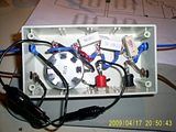
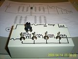
I have built an Inrush Current Limiter according to this design plan:
This "Switched Resistor Ladder" is useful for testing different scenarios, but is not recommended as a standard ICL. It has a high potential for operator error and is more complex than necessary.
Most of the technical discussion occurred on Endless Sphere .
The main purpose of building the device was to test other ICL ideas on the Vectux, like the Light Globe ICL option.
Although the Resistor ladder has a high operator error risk, it reduces the operator error risk during experimenting with ICL's because connections can be made and changed without much risk of shorting something!
Thanks to:
TylerDurden, Fechter, DaveS, Link and Garygid for helping!
Who's online
There are currently 0 users online.
Who's new
- eric01
- Norberto
- sarim
- Edd
- OlaOst


Comments
Re: Switched resistors and potentiometer as Vectrix Inrush ...
The development of this device continues on ES : http://www.endless-sphere.com/forums/viewtopic.php?f=14&t=9714
This information may be used entirely at your own risk.
There is always a way if there is no other way!
Re: Switched resistors and potentiometer as Vectrix Inrush ...
This sort of device works very well, I have run multiple tests with it.
It does not need as many steps as initially built into it; particularly the potentiometer and probably also the 20 Ohm resistor are superfluous.
If all the resistance steps are used, then it allows for a very gentle reconnection of the battery.
I replaced the 0.1 A fuses with 0.5 A fuses.
But it needs to be connected to the correct tabs, and needs to remain connected until the blue Andersons connector has been closed; if it is disconnected before the Andersons connector is closed then there will be potentially damaging inrush current again!
Details there: https://www.endless-sphere.com/forums/viewtopic.php?f=14&t=10096&view=next
This information may be used entirely at your own risk.
There is always a way if there is no other way!
Re: Switched resistors and potentiometer as Vectrix Inrush ...
Although this milti-resistor ladder can work well, there is too much possibility of operator-error, and the design is unnecessary overkill.
The simple one-resistor and an added set of SMALLER connectors is a lot easier.
See my post under light-bulbs, or the good discussion in the "endlsss sphere" forum.
Cheers, Gary
XM-5000Li, wired for cell voltage measuring and logging.
Re: Switched resistors and potentiometer as Vectrix Inrush ...
I agree!
I made the resistor ladder (learned a new word, thanks!) to be able to experiment and measure what happens when switching various resistors.
The peak current when connecting a cable with a resistor in it can easily be calculated by using Ohms law. But the peak current when switching from that resistor to practically zero resistance is much harder to determine in theory, because it depends on the current leakage of the capacitors and other elements connected to the circuit. I thought it's better to measure it!
I also had to be very cautious because some original Vectrix ICL's are apparently very complex. And I heard or read that Vectrix charges several hundred dollars for their ICL's. And then there were the reports about lengthy waits for repairs because the dealers were waiting for an ICL to be delivered.
Maybe the complexity of original Vectrix ICL's is only a red herring to fool people into believing that special equipment is needed to service them.
Or it might be an attempt to foolproof the device and make it capable of other (?diagnostic?) functions as well.
Ultimately, only the repeated use of any "rigged" device will prove beyond a doubt that it works for the Vectrix. The Vectrix is very complex and there will undoubtedly be some surprises during the development of suitable tools to repair it.
Therefore I approach the whole thing with "safety overkill" by default, because once I have broken some delicate IC or microprocessor in the Vectux, the game will be over. Vectrix Australia don't even have anyone able to do repairs anymore (hearsay, but I believe it), and even if they did, I could not afford the prices they charge for parts and repairs.
That's why I spent a few days planing and building the resistor ladder device, and about AU$20,-
First do no harm, and better safe than sorry!
I definitely do not recommend to build such a device unless it is for experimental purposes, but I think that the light bulb has a big advantage over a simple resistor as an ICL.
This information may be used entirely at your own risk.
There is always a way if there is no other way!