Light Globe as Inrush Current Limiter for Vectrix VX1?

Could a light globe be used as the resistor in the Inrush Current Limiter (ICL)?
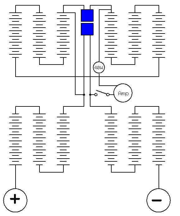
The circle with "40W" written in it represents a 240V, 40W incandescent light bulb.

The ammeter is optional, I would use it just to be able to see what residual current is still flowing when the globe stops to glow.
I believe the globe would actually light up whilst the capacitors on the motor controller are being pre-charged.
Here are some calculations regarding this:
40W = 240VAC x 0.16666A (Current flow through filament at 240V grid voltage)
240V / 0.166666A = 1.44kΩ (Resistance of HOT globe filament)
140VDC / 1.44kOhm = 97.2mA
The calculations are only approximate, for starters, maybe a RMS correction (factor 1.414) needs to be thrown in somewhere??? Comments, please!
.
Another factor is the variable resistance of the filament, depending on it's temperature:
From Wikipedia: http://en.wikipedia.org/wiki/Incandescent_light_bulbElectrical characteristics
Incandescent lamps are nearly pure resistive loads with a power factor of 1. This means the actual power consumed (in watts) and the apparent power (in volt-amperes) are equal. The actual resistance of the filament is temperature-dependent. The cold resistance of tungsten-filament lamps is about 1/15 the hot-filament resistance when the lamp is operating. For example, a 100-watt, 120-volt lamp has a resistance of 144 ohms when lit, but the cold resistance is much lower (about 9.5 ohms) [40] [41]. ....
For a 100-watt, 120 volt general-service lamp, the current stabilizes in about 0.10 seconds, and the lamp reaches 90% of its full brightness after about 0.13 seconds. [42]
.
The resistance of the cold filament might then be: 1.44kΩ / 15 = 96Ω
The current through that resistance, at 140VDC battery voltage, would be: 140V / 96Ω = 1.458A.
Please check these maths for me and comment if you can!
Who's online
There are currently 0 users online.
Who's new
- eric01
- Norberto
- sarim
- Edd
- OlaOst


Comments
Re: Light Globe as Inrush Current Limiter for Vectrix VX1?
Choices, choices.....
This information may be used entirely at your own risk.
There is always a way if there is no other way!
Re: Light Globe as Inrush Current Limiter for Vectrix VX1?
I have tested the light bulb as ICL option and found a 15W @ 240V globe the best option.
But the exact measurement of inrush currents is tricky due to their very short duration; maybe a 40W (@240V) globe is better, but I think they both work.
Details at: https://www.endless-sphere.com/forums/viewtopic.php?p=161880#p161880
This information may be used entirely at your own risk.
There is always a way if there is no other way!
Re: Light Globe as Inrush Current Limiter for Vectrix VX1?
Permanently installed connectors allow easy connection of a 320Ω (15W@240V) incandescent bulb to prevent damage due to inrush current.
More details there: https://www.endless-sphere.com/forums/viewtopic.php?p=163141#p163141
This information may be used entirely at your own risk.
There is always a way if there is no other way!
Re: Light Globe as Inrush Current Limiter for Vectrix VX1?
A low resistance to start and higher later is not prefered, the other way around would be better, but even a simple fixed resistor (10 to 100 ohms) would likely work as well. One just wants the "R" to be high enough to limit the V/R = I current to perhaps 10 amps or less, yet pass enough current (R low enough) to "equalize" in a few seconds (perhaps under 10 seconds). Since the current flows for only a short time, a high wattage (I*I*R = Watts) resistor is not really necessary. A 100 ohm resistor of 20 (or perhaps even 10) watts is likely to be sufficient.
So, for a fixed installation, one could just "cut" the wire going through the battery at any convenient spot, insert a switch (with heavy duty contacts, maybe 200 amps), then parallel the switch with the resistor. Then, open the switch before disconnecting the Andersons, and close the switch (about 20 seconds) after reconnecting the Andersons.
But, the proposed wiring, across the Andersons as shown above, should also "work", it just leaves one side connected. Better to use a 2-pole switch and disconnect both sides. Perhaps enen better is another (smaller) connector pair in place of the switch, if physical separation is desired. Then, plug in the smaller connectors first, wait some seconds, and then plug in the larger Anderson connectors.
Edit: I see that the good discussion in the "endless sphere" forum also suggests this simple small-connector (and one resistor) solution.
Cheers, Gary
XM-5000Li, wired for cell voltage measuring and logging.
Re: Light Globe as Inrush Current Limiter for Vectrix VX1?
Thank you for your thoughts on this!
The resistance of a light bulb does actually drop down again when the inrush current decreases and the filament cools down. The filament reduces it's temperature and resistance and ends up at with a resistance similar to the starting resistance. It does not heat the other parts of the globe up very much (due to the short duration of the inrush current), so that the filament has an effective heat sink.
This is most likely correct, but has a disadvantage: The inrush current will be so short that it would be easy to miss it, even if an indicator LED or something else was being used to confirm correct connection of the ICL.
An ICL which does not give feedback of proper operation will soon cause problems.
An ICL will be needed for many repairs to Vectrix scooters, but the Vectux is to my knowledge the only VX-1 with an option to install permanent tabs for ICL connection easily, because of the Manual-BMS (M-BMS) cables already in place.
The much more common approach to use an ICL will be to use temporary, insulation piercing connectors to connect to the cables coming from the rear battery to the blue Andersons connector, and normal clamps to connect to the tabs where the front battery connects to the front end of the Andersons connector. This unfortunately creates much opportunity for poor connection quality, or no connection at all, or connection to the wrong cell of the front battery. The cables could also be crossed over inadvertently, causing a 64V dead short the moment that the Andersons connector is closed. Not pretty!
A simple resistor will work if it is connected properly, but there is no easy and reliable way of knowing if it is connected properly. Once you hear a spark when you put the Andersons connector together it is too late, the fuse will have been exposed to an inrush current of several hundred amps, or worse!
In my opinion any ICL needs to have an indicator showing that it is working and that the inrush current has passed. A light bulb does both nicely and cheaply! Just see it light up and slowly fade out and you know that it is connected correctly.
Each of the cables used should also be fused to prevent disasters due to inadvertent connection to the wrong places.
The tabs of the M-BMS in my Vectux are fused at the junction to the cell, so I did not include another fuse into the light globe ICL circuit (I did include fuses in the resistor ladder ICL device discussed on another page because of it's high potential for operator error, and one of the 500mA fuses + the 800mA fuse in my DMM did actually blow "somehow").
The two batteries need to be separated completely to enable lifting of the rear battery out of the frame.
There is very little space for a switch, I think the installation of a permanent ICL connection point is a better solution. I did not install the light globe ICL permanently because the vibrations during scooter use will probably damage it.
Permanent installation of an ICL would also introduce an additional danger: The battery and motor controller might erroneously deemed to be "safe" after disconnection of the Andersons connector, but if an ICL was still connected, then the capacitors on the MC will remain fully charged and dangerous for months, until the battery is empty.
This information may be used entirely at your own risk.
There is always a way if there is no other way!
Re: Light Globe as Inrush Current Limiter for Vectrix VX1?
Another advantage of this type of ICL is that it will show that there is a fault if the fuse had failed due to some actual fault which made it necessary for the fuse to open.
In such circumstances any ICL which gives feedback that the capacitor charging has finished would NOT give such feedback, indicating that something is wrong and that the Andersons connector must not be closed.
The light globe would stay on, indicating the short / fault condition.
To reliably detect such states, a lower wattage light globe would be preferable over a higher wattage globe.
See this thread for an example: http://visforvoltage.org/forum/7846-vectrix-died-22000kshelp#comment-45204
This information may be used entirely at your own risk.
There is always a way if there is no other way!
Re: Light Globe as Inrush Current Limiter for Vectrix VX1?
Here is a link to a youtube video showing very nicely how to use a light=globe as ICL:
http://www.youtube.com/watch?v=208kG8B6HJM
Thank's to MitchJi for digging it up and to whoever made it!
http://visforvoltage.org/forum/9866-videos-access-encoder-planetary-gear#comment-54766
This information may be used entirely at your own risk.
There is always a way if there is no other way!
Re: Light Globe as Inrush Current Limiter for Vectrix VX1?
What do the better qualified members of the forum think about "elevating" the light globe ICL method to some sort of "well tested and reliable" status?
This information may be used entirely at your own risk.
There is always a way if there is no other way!
Re: Light Globe as Inrush Current Limiter for Vectrix VX1?
Using a light globe as an ICL seems like a really good method to me. My Vectrix's main fuse blew last week. I was maintaining 50 km/h up a slight incline, and then suddenly lost all throttle/regen, and the dashboard lights went out a few seconds later, just like every other person's fuse that's blown. I've now removed the blown fuse (and did it without removing the rear battery!) and ordered an FWX-200A fuse to replace it.
I'm planning on using a 15-25W (depending on what's available) globe bulb as an ICL. If anyone has additional advice please let me know.
Thanks to everyone who has tested this, especially Mik!
Re: Light Globe as Inrush Current Limiter for Vectrix VX1?
Hello, I just want to whatch the video but this web page does not let me do it because I have to log in but I have already done that. Thats why I am wriying right now.