Vectrix Stock BMS (Battery Management System)

This page serves to analyse the Stock Battery Management System (BMS) of the Vectrix VX-1.
How does it work?
Could it be improved?
Will it get along with different batteries or additions to the stock system?
.............................................................................................................
.............................................................................................................
The system is software controlled and it's behaviour depends on the software version installed in the scooter.
.
There is no active balancing of cells apart from slow overcharging of the entire 102-cell string.
.
Voltage monitoring occurs through this voltage divider:


Note: There is high voltage between V1, GND and V2 on the PCB of the rear battery temp sensor board / voltage divider board! The tab cables are not fused at the cell level and shorting across the soldered connections on the PCB could cause serious problems, even after disconnection of the main battery connector between the batteries!
.
.
Two 12V impellers suck air through the batteries for cooling purposes. Whilst electrically the battery is a 102serial string, for airflow cooling purposes it is an 34-parallel, 3-serial setup. This causes problems because there is often a temperature gradient between the 3-s layers.


.
.
Thermal monitoring occurs through 12 temperature sensors placed throughout the battery, one near the center of each module of cells. There are probably other temperature sensors elsewhere to monitor air temperature, motor controller temperature etc.


Who's online
There are currently 0 users online.
Who's new
- eric01
- Norberto
- sarim
- Edd
- OlaOst
Support V is for Voltage

Comments
Re: Vectrix Stock BMS (Battery Management System)
There is a possibility to "switch off" the BMS. Some Batteries even don´t have any Voltage monitors installed.
This could be useful for conversions, but could be a problem as the system does not recognize uneven Parts of
the battery. A photo of an board without voltage-monitor will follow.
Greetings mitbike
Lethal voltages! Leave it to someone who knows how to deal with it!
Re: Vectrix Stock BMS (Battery Management System)
Very interesting indeed!
Do I understand it correctly that the solder blob on SH1 is that "Short" which has been done along with attaching the cables at J8 ?
This information may be used entirely at your own risk.
There is always a way if there is no other way!
Re: Vectrix Stock BMS (Battery Management System)
Just copying a relevant post from another thread into here, where it belongs:
(See: http://visforvoltage.org/forum/6462-bathot-during-riding-battery-fans-won039t-start-during-ride-why-not#comment-38458)
The below calculations of current draw through the voltage divider are important when longer-term storage is required. Some of this current drain will continue even if the blue mid-pack connector is opened and/or if the main fuse is blown (this affects the first 27 cells at the negative end of the battery).
This information may be used entirely at your own risk.
There is always a way if there is no other way!
Re: Vectrix Stock BMS (Battery Management System)
Hi,
you don´t need the voltage sensors. There are V´s without them on the road. Take a look at Stock BMS one of the last posts. I´ve seen temp.-boards
without the voltagesensors. All you have to to is to open a soldered contact on the board (disconected from battery and Scooter!)
In this case "SH1" was open and no wiring (V1,GND,V2) was soldered to the board. BUT: bevore soldering check the voltage on the disconnected
board, otherwhise the condesators may give you some "kick"
Foto of the other type will follow.
Greetings Mike
Re: Vectrix Stock BMS (Battery Management System)
SH1 simply defines whether the PCB is for the front or back pack. It has nothing to do with the wires, other than they are both on the back PCB.
Re: Vectrix Stock BMS (Battery Management System)
Hi, here is one board without voltage monitor.
So the text on the board is a little bit confusing. I´ve seen one battery pack without
the J8-v-mon wiring, but did not photograph both boards to check if on one board the
jumper was set or not
Greetings Mike
Re: Vectrix Stock BMS (Battery Management System)
And the front PCB temp sensor wires are white, the back ones are black.
The PCB shown by Mikemitbike without voltage divider cables is from the front battery. They never have voltage divider cables.
This information may be used entirely at your own risk.
There is always a way if there is no other way!
Re: Vectrix Stock BMS (Battery Management System)
The resistors R14 and R8 are soldered 180deg compared to R15 and R11.
This has caused a error in the schematic
Please confirm that both resistor dividers are
R14 + R8 T R9 + R10
10K + 200 T 430K + 2K
R15 + R11 T R12 + R13
10K + 200 T 430K + 2K
Thanks
Re: Vectrix Stock BMS (Battery Management System)
Thanks for spotting the error!
I have now amended the schematic in the first post.
This information may be used entirely at your own risk.
There is always a way if there is no other way!
Re: Vectrix Stock BMS (Battery Management System)
Can seem to edit my post but it the schematic links/points to http://i281.photobucket.com/albums/kk217/Mr_Mik/Vectux/S-BMS/VectrixBatteryandMC41andVoltageDivi.jpg
So if this updates then my posts schematic will change too.
I was trying to understand current measurement in the Vectrix.
The only current measurement appears to be on the Main Controller Board with DC Hall sensing from the battery and out on TWO of the Motor phases.
Is there an overall schematic for the Vectrix showing the current sensing?
Re: Vectrix Stock BMS (Battery Management System)
I edited the schematic so the error is clearly visible now. In case the image has been linked elsewhere it should also show up.
It would be very nice if we could work on schematics collaboratively. The ones I have clobbered together are obviously in need of thorough checking!
This information may be used entirely at your own risk.
There is always a way if there is no other way!
Re: Vectrix Stock BMS (Battery Management System)
hello
I am writing from Denmark, and hope you can help me, unfortunately my BMS (the one with the white wires from the front battery range, fired), you can tell where it is possible to buy a new one?
a Vectrix vx-1 vintage 2010.
sincerely,
Finn Mortensen
Re: Vectrix Stock BMS (Battery Management System)
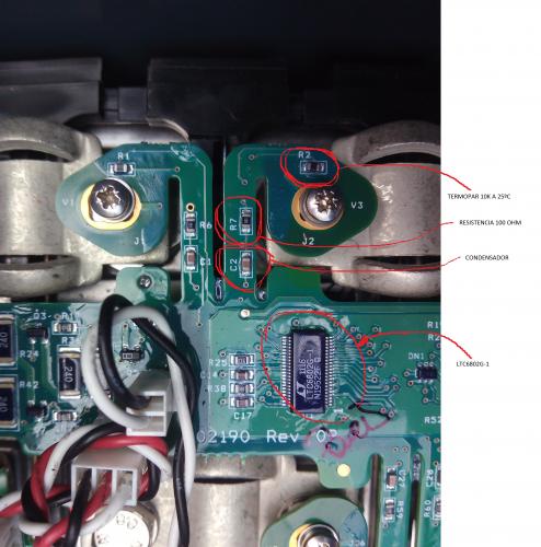
Hello everyone, I have a Vectrix battery, with battery pack since 2012. My autonomy is not bad, I can perform well 70 80km. Reviewing software tensions scooterdiagg I see there cells that show discrepancies cosiderables full load voltages around 0.1 to 0.2 volts.
When removing the battery pack I find that all cells, measuring with tester, are balanced to 3.3 V
The BMS circuit boards do not function properly, do not measure the cell voltage correctly.
BMS analyzing the heart of it is the LTC6802g-1 integrated circuit, responsible for measuring voltages by analog to digital converter.
http://cds.linear.com/docs/en/datasheet/68021fa.pdf
 ve
ve
The resistance that often fail in the photo frame, switch 100 ohm resistors in the modules fail. Once repaired vovler to apply protective coating against corrosion.
After my bike intervention measures voltages and load perfectly well all cells
I hope you ser
Re: Vectrix Stock BMS (Battery Management System)
Hello every body, (any body?)
I'm looking for a BMS See Photo.
The one I already have comes from a Li-ion version, 180 Km range. 10 pieces were made for France. In 2017-2018.
Thank you.
I can buy the whole scooter.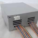
Re: Vectrix Stock BMS (Battery Management System)
I’ve been using the stock Vectrix VX1 universal BMS with my leaf conversion for about 2 years. The main problem I’ve had was connecting (with inrush resister) the battery with the BMS connected & wired in. This fried Board3 and I replaced it. This happened again and the board was repaired twice and now seems ok..would have been helpful to have instructions to wires in after battery connected to avoid instant death to board3. Other than that it seems to do the job preventing cell high or low voltage and seems to balance them well however, the 1st charge cycle balancing mode seems to take days to finish as it happens very slowly! I feel safer with it being there. I have now fitted a 200amp dc breaker and inrush circuit which means I can isolate the battery fully and turn it back on without BMS damage.